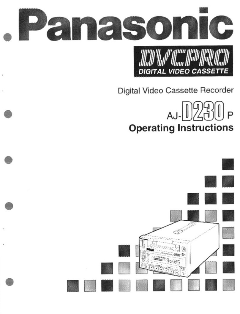
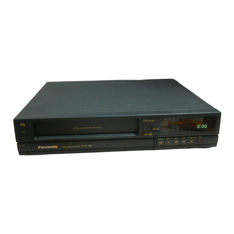
Controls and Connection Sockets
z
q
O
111 NOISE FILTER
OFF: For normal VTR operation.
ON:
For playback of a cassette whose recording
quality is inferior.
ItE)
VTR 1/VTR
2
VTR 1: Set at this position on both the VTR and
remote controller for normal use with one VTR.
VTR 2: Set at this'position when using two Panasonic
VTRs.
This allows the remote controller to be set for
operating VTR 1 or VTR 2.
® VTR/TV
To select the VTR mode or TV mode.
110 AUDIO DUB
To set up the VTR for audio dubbing.
A.DUB indicator lights up.
•
INSERT
To set up the VTR for insert editing.
INSERT indicator lights up.
•
Hi-Fi/NORMAL MIX
OFF: Normally set at this position to reproduce the
better sound available from the Hi-Fi track.
ON:
Both sound tracks are played back mixed
together. Use this setting when playing back a
cassette tape which has been insert edited or
audio dubbed.
IS Infra-red Remote Control Receiver Window
a)
Display
•
CHECK/PROG
To select a timer programme number.
"1, 2, 3... or 8" is lit.
To display details of preset timer recording.
e
-+/V
A
To set the clock and timer recording.
To select the required programme position (TV
station).
®
NEXT/SP/LP
To proceed to the next item during setting procedure
To select the tape speed required for recording.
SP gives the best picture quality.
LP gives the longest recording time.
®
SHIFT/SLEEP
To blank unoccupied programme position.
To set the time to turn off the VTR automatically.
(31
)
REC
To start a recording.
ED
TIMER REC
To turn the timer recording function on and off.
El is lit or not lit.
The VTR can only be operated manually when the
timer recording function is off.
e
MIC
To connect a microphone for recording.
•
Jog Dial
To locate any desired frame with utmost precision.
e
Shuttle Ring
In the stop mode: To rewind or fast forward the tape.
In the playback mode:
To search picture backward or
forward.
In the still playback mode:
To adjust playback speed backward
or forward.
In the rewind or fast forward mode:
To obtain high speed picture.
•
RF OUT
To connect to the aerial terminal on a TV set.
•
Video Playback Channel Selector
To select the video playback channel.
•
AUDIO IN
To connect the audio cable to a video camera or
another video recorder.
€1:1 VIDEO IN
To connect the video cable to a video camera or
another video recorder.
6
D
AUDIO OUT
To connect the audio cable to a TV or another video
recorder.
e
VIDEO OUT
To connect the video cable to a TV or another video
recorder.
•
RF IN
To connect to the external aerial.
•
TEST SIGNAL
The test signal is transmitted on channel L or H.
•
Signal Ground Terminal
To connect the Signal Ground Terminal to the ground
to reduce the noise from microphone cable.
9
AC IN—
To connect to the main power supply.
11