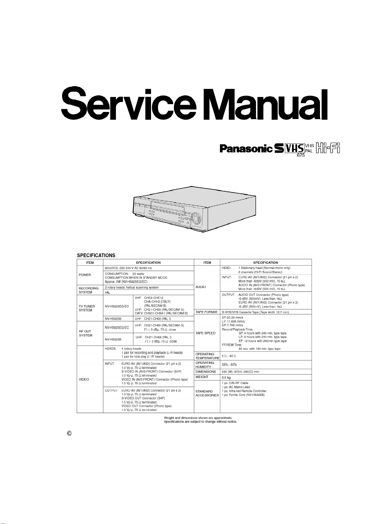
Panasonic NV-HS825EG User manual
Other Panasonic VCR System manuals

Panasonic
Panasonic Omnivision PV-HD1000 User manual

Panasonic
Panasonic Omnivision PV-4611 User manual

Panasonic
Panasonic OmniVision PV-C1324-K User manual

Panasonic
Panasonic AGTL950 - TIME LAPSE VCR User manual

Panasonic
Panasonic NV-FJ623 User manual

Panasonic
Panasonic NV-FJ600 Series User manual

Panasonic
Panasonic NV-SJ220EG User manual

Panasonic
Panasonic Omnivision PV-8455S User manual

Panasonic
Panasonic AG-MD830E User manual

Panasonic
Panasonic NV-HV62PX User manual

Panasonic
Panasonic NV-VP60GL User manual

Panasonic
Panasonic NV-HV61GH User manual

Panasonic
Panasonic NV-SD420 Series User manual

Panasonic
Panasonic AJD230HP User manual

Panasonic
Panasonic NV-HD90 User manual

Panasonic
Panasonic AGRT600AP - TIME LAPSE RECORDER User manual

Panasonic
Panasonic NV-HV50 Series User manual

Panasonic
Panasonic Omnivison VCRplus+ PV-V4611 User manual

Panasonic
Panasonic NV-HS1000EC User manual

Panasonic
Panasonic Omnivision PV-V4621 User manual