Panasonic YC-300BZ3YHD User manual

Before operating this product, please read the instructions carefully and save this manual for future use.
Please also read the operating instructions of peripheral equipment.
First, please read the “Safety Precautions”.
English version is the original instructions.
2011
Operating Instructions
Model No. YC-300BZ3YHD
Fully digital and inverter controlled TIG welding
OMCTT5621E18
DC TIG Welding Power Source

Features
OMCTT5621E18
2
Warning symbols for safe usage
Each symbol describes things to be observed to prevent you and other personnel from hazardous conditions or damage to property.
Disclaimer
Panasonic Smart Factory Solutions Co., Ltd., (hereinafter
called “PSFS”) and its affiliates (including any subcontrac-
tor, sales company or agent) shall not assume or undertake
any responsibility or liability of the followings:
• Any problem arising out of, or directly or indirectly attributable to,
the failure of user to carry out those normal installation, normal
maintenance, normal adjustment and periodical check of this
Product.
• Any problem arising out of any Force Majeure, including but not
limited to, act of God.
• Any malfunction or defect of this Product that is directly or indi-
rectly the result of any malfunction or defect of one or more
related parts or products that are not supplied by PSFS. Or any
problem arising out of, or directly or indirectly attributable to, the
combination of this Product with any other product, equipment,
devices or software that is not supplied by PSFS.
• Any problem arising out of, or directly or indirectly attributable to,
user’s failure to strictly carry out or follow all of the conditions
and instructions contained in this instruction manual, or user’s
misusage, mishandle, operational miss or abnormal operation.
• Any problem arising out of this Product or the use of it, the
cause of which is other than the foregoing but is also not attrib-
utable to PSFS.
• Any claim of a third party that this Product infringes the intellec-
tual property rights of such third party that are directly or indi-
rectly caused by User’s use of this Product and relate to the
method of production.
ANY LOST PROFITS OR SPECIAL, INDIRECT, INCIDEN-
TAL OR CONSEQUENTIAL DAMAGES IN CONNECTION
WITH OR ARISING FROM ANY MALFUNCTION,
DEFECT OR OTHER PROBLEM OF THIS PRODUCT.
The followings explains hazardous conditions or damages that are classified
into the following three levels.
The following symbols indicates things to
be observed.
A hazardous situations including death
or serious personal injury is imminent.
Things that MUST
NOT be performed.
The potential for a hazardous accident
including death or serious personal
injury is high.
Things that MUST be
performed.
The potential for hazardous accident
including light personal injury and/or the
potential for property damage are high.
Things attention must
be paid to.
DANGER
WARNING
CAUTION
The description of this manual is based on the contents as of November, 2020.
The contents of this manual are subject to change without further notice.
Features
• It is excellent in reproducing the welding conditions
because it is fully digital.
• It can store and recreate up to 64 welding conditions.
• Its enhanced communication function enables introduc-
tion of information technology into the welding sites.
• It is compact and lightweight. (Weight: 36 kg)
• It comes with a fingertip joint for connecting the base
material cable.

OMCTT5621E18 3
Cautions about electromagnetic disturbance
(1) Extra precaution may be required when welding power
source is used in a domestic establishment.
(2) Before installing welding equipment, the user shall
make an assessment of potential Electromagnetic
problems in the surrounding area as below.
(a) Other supply cables, control cables, signaling and
telephone cables; above, below and adjacent to
the welding equipment;
(b) Radio and television transmitters and receivers;
(c) Computer and other control equipment;
(d) Safety critical equipment, e.g. guarding of indus-
trial equipment;
(e) The health of the people around, e.g. the use of
the pacemaker and hearing aids;
(f) Equipment used for calibration or measurement;
(g) The immunity of other equipment in the environ-
ment; the user shall ensure that other equipment
being used in the environment is compatible; this
may require additional protection measures;
(h) The time of day that welding or other activities are
to be carried out.
(3) The user shall be observe to reduce emission distur-
bance as below.
(a) Welding equipment should be connected to mains
supply according to the manufacture's recommen-
dations.
(b) Welding equipment should be routinely maintained
according to the manufacture's recommendations.
(c) The welding cables should be kept as short as
possible and should be positioned close together,
running at or close to the floor level.
(d) Confirm to connection of all metallic component in
the welding installation and adjacent to it should
be considered for safety.
(e) The work-piece should be connected to earth for
electric safety.
(f) Selective screening and shielding of other cables
and equipment in the surrounding area may allevi-
ate problems of interference. Screening of entire
welding installation may be considered for special
applications.
(4) The user should take the responsibility with respect to
interference from welding.

OMCTT5621E18
4
About “Turkish RoHS Regulation”
About “Ukrainian RoHS Regulation”
EEE Complies with Directive of Turkey.
English Declaration of Conformity
with the requirements of Technical Regulation on the Restriction Of the use of certain Hazardous
Substances in Electrical and Electronic Equipment
(adopted by Order №1057 of Cabinet of Ministers of Ukraine)
The Product is in conformity with the requirements of Technical Regulation on the Restriction Of the
use of certain Hazardous Substances in electrical and electronic equipment (TR on RoHS).
The content of hazardous substance with the exemption
of the applications listed in the Annex №2 of TR on RoHS:
1. Lead (Pb) - not over 0,1wt % or 1000wt ppm;
2. Cadmium (Cd) - not over 0,01wt % or 100wt ppm;
3. Mercury (Hg) - not over 0,1wt % or 1000wt ppm;
4. Hexavalent chromium (Cr6+) - not over 0,1wt % or 1000wt ppm;
5. Polybrominated biphenyls (PBBs) - not over 0,1wt % or 1000wt ppm;
6. Polybrominated diphenyl ethers (PBDEs) - not over 0,1wt % or 1000wt ppm.
Ukrainian Декларація про Відповідність
Вимогам Технічного Регламенту Обмеження Використання деяких Небезпечних Речовин в
електричному та електронному обладнанні
(затвердженого Постановою №1057 Кабінету Міністрів України)
Виріб відповідає вимогам Технічного Регламенту Обмеження Використання деяких
Небезпечних Речовин в електричному та електронному обладнанні (ТР ОВНР).
Вміст небезпечних речовин у випадках, не обумовлених в Додатку №2 ТР ОВНР, :
1. свинець(Pb) – не перевищує 0,1wt % ваги речовини або в концентрації до 1000 частин
на мільйон;
2. кадмій (Cd)– не перевищує 0,01wt % ваги речовини або в концентрації до 100 частин на
мільйон;
3. ртуть(Hg) – не перевищує 0,1wt % ваги речовини або в концентрації до 1000 частин на
мільйон;
4. шестивалентний хром (Cr6+ ) – не перевищує 0,1wt % ваги речовини або в концентрації
до 1000 частин на мільйон;
5. полібромбіфеноли (PBB) – не перевищує 0,1% ваги речовини або в концентрації до
1000 частин на мільйон;
6. полібромдефенілові ефіри (PBDE) – не перевищує 0,1wt % ваги речовини або в
концентрації до 1000 частин на мільйон.
Russian Декларация о Соответствии
Требованиям Технического Регламента об Ограничении Использования некоторых Вредных
Веществ в электрическом и электронном оборудовании
(утверждённого Постановлением №1057 Кабинета Министров Украины)
Изделие соответствует требованиям Технического Регламента об Ограничении
Использования некоторых Вредных Веществ в электрическом и электронном оборудовании
(ТР ОИВВ).
Содержание вредных веществ в случаях, не предусмотренных Дополнением №2 ТР ОИВВ:
1. свинец (Pb) – не превышает 0,1wt % веса вещества или в концентрации до 1000
миллионных частей;
2. кадмий (Cd) – не превышает 0,01wt % веса вещества или в концентрации до 100
миллионных частей;
3. ртуть (Hg) – не превышает 0,1wt % веса вещества или в концентрации до 1000
миллионных частей;
4. шестивалентный хром (Cr6+)– не превышает 0,1wt % веса вещества или в
концентрации до 1000 миллионных частей;
5. полибромбифенолы (PBB) – не превышает 0,1wt % веса вещества или в концентрации
до 1000 миллионных частей;
6. полибромдифеноловые эфиры (PBDE) – не превышает 0,1wt % веса вещества или в
концентрации до 1000 миллионных частей.

OMCTT5621E18 5
Table of Contents
Features................................................ 2
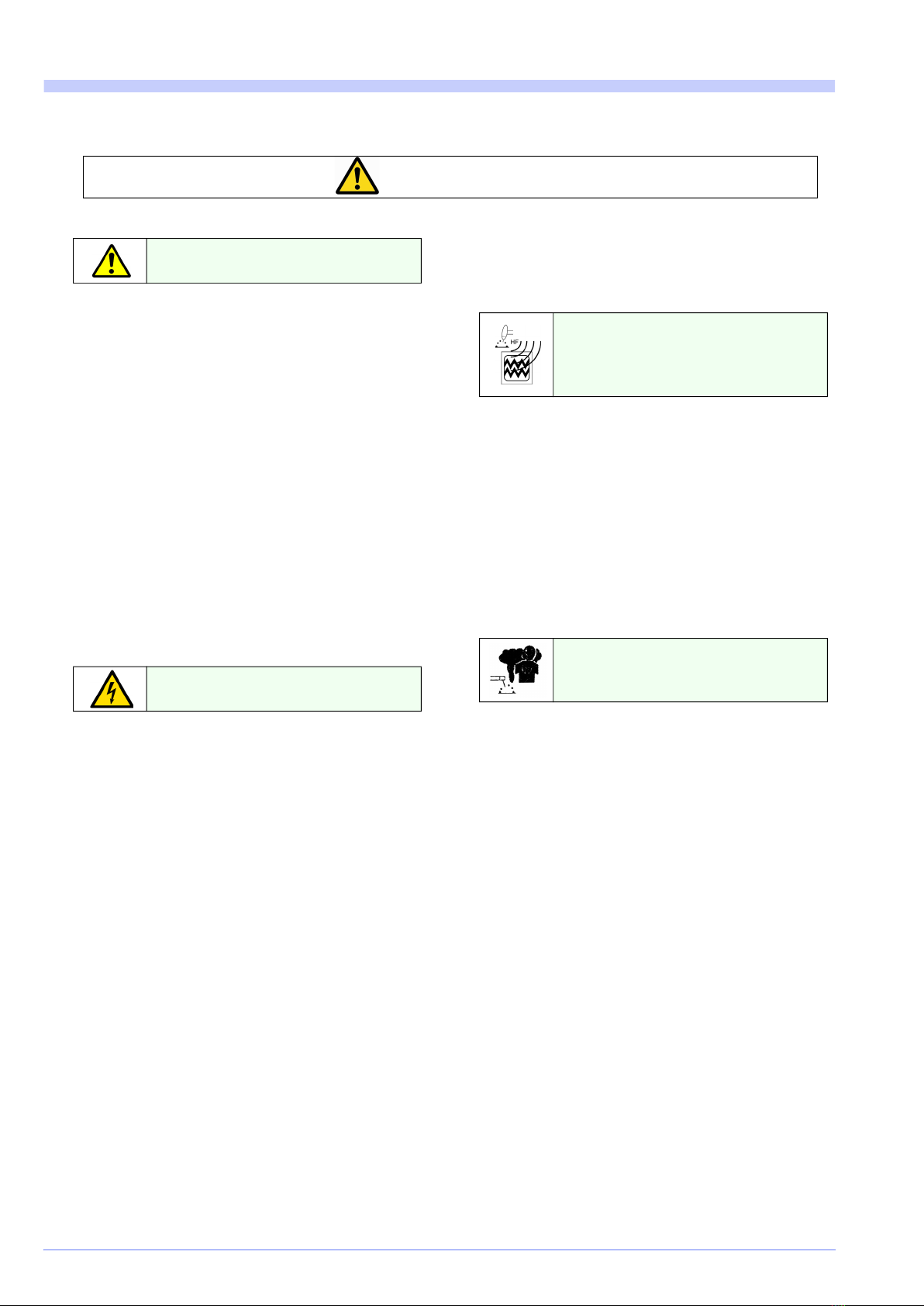
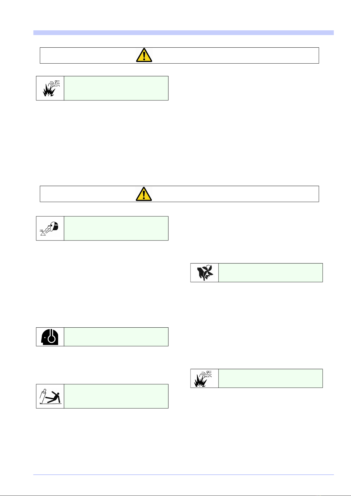
1.Safety precautions ........................... 6
2.Rated Specifications ........................ 8
2.1Standard accessories............................ 8
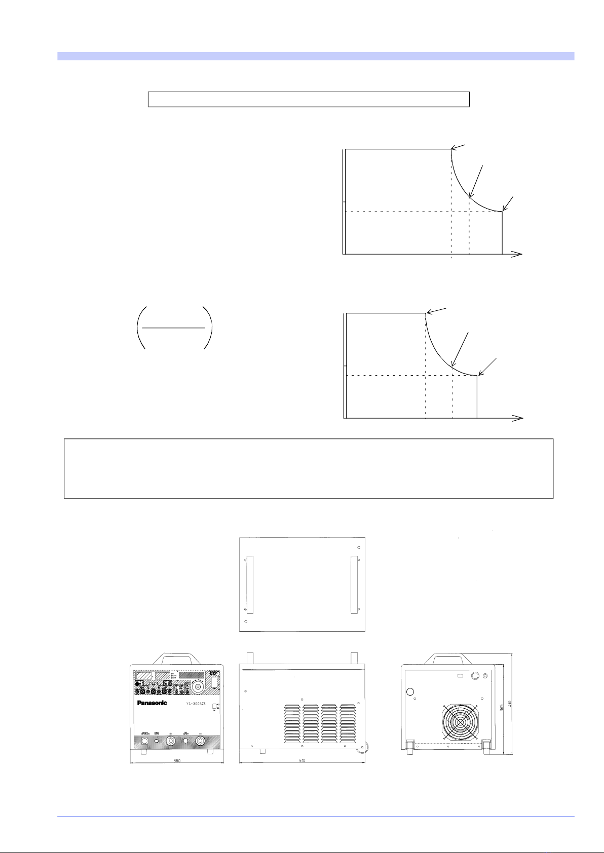
2.2Duty cycle ............................................... 9
2.3Dimensions............................................. 9
3.Installation......................................... 10
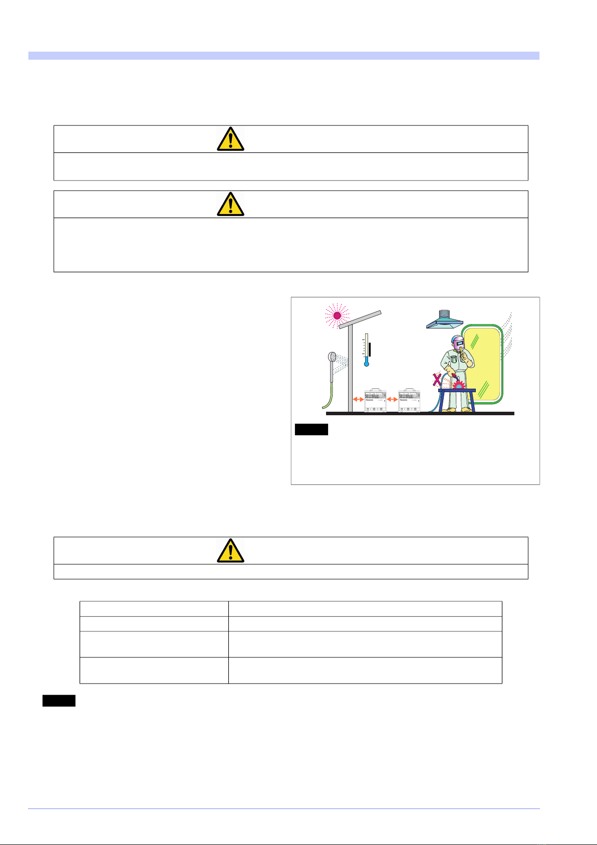
3.1Installation siter ..................................... 10
3.2Power supply equipment ...................... 10
4.Configuration.................................... 11
4.1TIG welding............................................. 11
4.2Stick welding .......................................... 12
4.3Peripheral equipment (Optional items) 13
4.3.1TIG Welding torch....................................... 13
4.3.2Extension cable (available on request)....... 15
4.3.3Argon gas regulator (YX-251A) .................. 17
4.3.4Cooling water unit and cooling water.......... 17
4.3.5Cooling water.............................................. 18
4.3.6Potentiometer-type remote control unit (YC-
30BPR1, YC-30BMR1) .............................. 18
4.3.7External equipment connection unit (YX-
CB009Y**) ................................................. 18
5.Names and Functions ...................... 19
5.1Front panel ............................................. 19
5.1.1Data display/setting section and welding
conditions selecting section ....................... 19
5.1.2Welding conditions setting buttons section. 20
5.1.3Switches and rear side ............................... 21
6.Connection........................................ 22
6.1Connecting output cables for TIG or SPOT
welding.................................................... 22
6.2Connecting output cables for STICK
welding.................................................... 23
6.3Connecting input cables ....................... 23
6.3.1Connecting grounding wire and input power cable
................................................................... 23
6.4Connecting gas regulator ..................... 24
6.4.1Connecting procedures............................... 24
6.4.2Connecting procedures............................... 24
6.5Connecting with jig(s) ........................... 25
6.5.1Connections................................................ 25
6.6Connecting with Robot.......................... 28
6.6.1Connection.................................................. 28
6.7Connecting with external device
connecting unit (YX-CB009Y**) ............ 28
6.7.1Connection.................................................. 28
7.Preparation and termination
processing ....................................... 29
7.1Preparation ............................................. 29
7.1.1Use of protective equipment ....................... 29
7.1.2Pre-operation check.................................... 29
7.1.3Turning ON power....................................... 29
7.1.4Adjusting gas flow rate................................ 29
7.2Termination processing (steps after
welding operation).................................. 30
7.2.1Shutting off gas ........................................... 30
7.2.2Shutting off power ....................................... 30
7.2.3Precautions for use of water-cooling torch in
winter season............................................. 30
8.Settings.............................................. 31
8.1DETAIL settings...................................... 31
8.1.1Factory settings........................................... 31
8.1.2How to check settings ................................. 32
8.1.3How to change settings............................... 32
8.1.4How to restore the original factory settings of this
product....................................................... 33
8.1.5Memory deletion ......................................... 34
8.1.6Memory lock................................................ 35
8.2Welding conditions ................................ 36
8.2.1Settings and checking................................. 36
8.2.2Welding condition setting table ................... 37
8.2.3About welding conditions ............................ 37
8.2.4Storing welding conditions .......................... 38
8.2.5Reproducing welding conditions ................. 38
9.Operation........................................... 39
9.1TIG Welding operation ........................... 39
9.2SPOT welding operation ........................ 42
9.3STICK welding operation ....................... 42
10.Maintenance and inspection.......... 43
10.1Daily check............................................ 43
10.1.1Welding machine (This product) ............... 43
10.1.2Cables and hoses ..................................... 44
10.2Periodic check ...................................... 44
10.2.1Check guideline ........................................ 45
10.2.2[Time period for which customers-set conditions
can be maintained] .................................... 45
10.3Precautions for withstand voltage test and
insulation resistance measurement ..... 46
11.Troubleshooting ............................. 47
11.1Error codes and messages.................. 47
11.2Troubleshooting table.......................... 49
12.Parts list........................................... 50
13.Circuit diagram ............................... 52
14.Appendix ......................................... 54
14.1TIG Welding conditions table - (Reference)
.................................................................. 54
14.2Tungsten welding rod .......................... 55
14.3TIG welding shield gas......................... 55
14.4Filler wire............................................... 55
14.5Welding conditions memorandum...... 56
14.6Program list........................................... 57
15.Information on Disposal................. 58

Safety precautions
OMCTT5621E18
6
1. Safety precautions
Welding power source
(1) Never use the welding power source for other than
welding purpose. (e.g. Never attempt to use the weld-
ing power source for pipe thawing.)
(2) It is very important to comply with all instructions,
safety warnings, cautions and notes mentioned. Fail-
ure to do so can result in serious injury or even death.
(3) Work of driving source at the input side, selecting work
site, handling, storage and piping of high pressure gas,
storage of welded products and also disposal of waste
should be performed according to the operating
instruction and national, state and local codes and reg-
ulations.
(4) Prevent any unauthorized personnel to enter in and
around the welding work area.
(5) Only educated and/or skilled persons who well under-
stand this welding power source should install, oper-
ate, maintain and repair the unit.
(6) Only educated and/or skilled persons who well under-
stand the operating instruction of the unit and are
capable of safe handling should perform operation of
the unit.
Against electric shock
(1) Grounding of the case of the welding power and base
metal or a jig electrically connected to the base metal
must be performed by educated and/or skilled per-
sons.
(2) Before installation or maintenance work, turn off power
at the power box, wait it for at least five minutes to dis-
charge capacitors. Significant voltage may exist on
capacitors after turning off power at the power box so it
is imperative to check to make sure that no charged
voltage present at capacitors before touching any
parts. Do not use undersized, worn, damaged or bare
wired cables.
(3) Connect cables completely and insulate connection
parts.
(4) Keep all cases, panels and covers securely in place.
(5) Do not handle the welding power source with torn or
wet gloves.
(6) Wear safety harness in case of working above floor
level.
(7) Turn off all equipment when not in use.
(8) Perform periodic checks without fail and repair or
replace any damaged parts before using the power
source.
(9) In case of AC arc welding in a confined area or above
floor level, check related national, state and local
codes and regulations for any special treatment and
comply with it if any.
Electromagnetic disturbance
(1) Pacemaker wearers should consult their doctor before
going near arc welding. Magnetic fields can affect
pacemakers.
(2) Peripheral electronics or safety device may cause
electromagnetic disturbance. Ground all of such
devices without fail. Provide an electromagnetic
shielding if necessary.
(3) Weld cable should be as short as possible and also lay
it as near to the floor or ground as possible if not on.
(4) Never provide grounding of base metal and welding
machine in common.
(5) Do not operate the torch switch if not necessary.
Ventilation and protective equipment
(1) When conducting welding in the bottom of the tank,
boiler or hold as well as legally-defined sites, use a
local exhauster specified by the applicable laws and
regulations (occupational safety and health regulation,
rules on preventing suffocation or etc.) or wear protec-
tive breathing gear.
(2) To prevent dust injury or poisoning by the fume gener-
ated during welding, use a local exhauster specified by
the applicable law (occupational safety and health reg-
ulation, rules on preventing injury by inhaled dust or
etc.), or wear protective breathing gear.
If a protective breathing gear is used, it is recom-
mended to use one with an electric fan with high pro-
tection performance.
(3) When conducting welding in a confined area, make
sure to provide sufficient ventilation or wear protective
breathing gear and have a trained supervisor observe
the workers.
(4) Do not conduct welding at a site where degreasing,
cleaning or spraying is performed. Conducting weld-
ing near the area where any of these types of work is
performed can generate toxic gases.
(5) When welding a coated steel plate, provide sufficient
ventilation or wear protective breathing gear. (Welding
of coated steel plates generates toxic fume and gas.)
WARNING
Observe the following instructions
to prevent the hazard.
Observe the following instructions
to prevent the hazard.
Observe the following instructions
to prevent the electromagnetic
disturbance due to weld current or
high frequency at arc start.
Oxygen deficit, fume and gas
generated during welding can be
hazardous.

Safety precautions
OMCTT5621E18 7
Against fire, explosion or blowout
(1) Remove any combustible materials at and near the
work site to prevent them from being exposed to the
spatter. If they cannot be relocated, cover them with a
fireproofing cover.
(2) Do not conduct welding near combustible gases.
Do not place the welding power source near combusti-
ble gases, otherwise, such gases may catch fire from a
spark of electricity inside the welding power source as
it is electric equipment.
(3) Do not bring the hot base metal near combustible
materials immediately after welding.
(4) When welding a ceiling, floor or wall, remove all flam-
mables including ones located in hidden places.
(5) Wire the cables correctly and connect them tightly.
Insulate the connected parts surely so that no exposed
conductive part touches the cases or housings. (Poor
cable connection or incomplete current path on the
base metal side, such as steel, if any, can cause fire
due to the heat generated by energization.)
(6) Connect the base metal cable as close to the welding
position as possible. (If not, unexpected current path
may be created, which can cause fire due to the heat
generated by energization.)
(7) Properly connect cables and insulate connected parts.
Improper cable connections or touching of cables to
any electric current passage of the base metal, such
as steel beam, can cause fire.
(8) Do not weld a sealed tank or a pipe that contains a gas.
(9) Keep a fire extinguisher near the welding site for an
emergency.
Installing shielding (curtain etc.)
(1) When welding or monitoring welding, wear safety
glasses with sufficient light blocking performance or
use a protective mask designed for welding operation.
(2) Wear protective glasses to protect your eyes from
spatter or slugs.
(3) When welding or monitoring welding, wear protective
clothes designed for welding operation, such as
leather gloves, leg cover and leather apron, and also
wear long-sleeve shirts.
(4) Install a protective curtain around the welding manipu-
lator site to prevent the arc flash from entering the
eyes of people in the surrounding area.
Noise
(1) Follow the local regulations and wear ear protection,
such as ear plug or hear muff.
(2) The larger the welding current is, the larger the noise
becomes.
Gas cylinder and gas flow regulator
(1) The gas cylinder must be handled properly according
to the applicable law and in-house standards.
(2) Use the gas flow regulator that is supplied or recom-
mended by our company.
(3) Read the instruction manual of the gas regulator prior
to using it, observe the cautions in the manual
(4) Secure the gas cylinder to a dedicated gas cylinder
stand.
(5) Do not expose the gas cylinder to high temperature.
(6) When opening the valve of the gas cylinder, do not
bring your face close to the discharge outlet.
(7) When the gas cylinder is not used, be sure to install a
protective cap.
(8) Do not hang the welding torch on the gas cylinder, or
touch the gas cylinder with the electrode.
Rotating parts
(1) Keep away from rotating parts such as cooling fans,
feed roller of the wire feeder, or hand, finger(s) hair or
part of your clothes may be caught by the parts result-
ing in injury.
(2) Keep all covers, panels and cases closed when using
the product.
(3) Maintenance work and repair should be perform only
by educated and/or skilled persons who thoroughly
understand welding machines. While performing
maintenance or repair work, provide fence or the like
around the welding machine so that unauthorized per-
son can not come close carelessly.
Against insulation deterioration
(1) Keep enough distance from welding power source
when performing welding or grinding work so as to pre-
vent such spatters or iron particles from getting into the
power source.
(2) Perform check and maintenance work periodically so
as to prevent insulation deterioration due to accumu-
lated dust or dirt.
(3) When spatters or iron particles get into the welding
power source, turn off the power switches of the weld-
ing power source and power distribution box, and then
blow out.
WARNING
Observe the following cautions to
prevent fires explosion or blow-
out.
CAUTION
Arc flash, flying spatter and slugs
generated during welding can dam-
age your eyes, skin and hearing.
Noise from some processes or
equipment can damage hearing.
Overturn of gas cylinder and
blowout of gas flow regulator can
cause injury.
Rotating parts can cause injury.
Insulation deterioration can cause
fire of welding power source.

Rated Specifications
OMCTT5621E18
8
2. Rated Specifications
2.1 Standard accessories
Rated input voltage VAC 400
Number of Phase 3
Rated frequency Hz 50/60 Hz (Common)
Rated input 10.5 kVA (9.5 kW)
Efficiency % 84
Idle state power consumption W 59
Rated output
current
TIG, SPOT A DC 300
STICK A DC 250
Rated output
voltage
TIG, SPOT V DC 22
STICK V DC 30
Duty cycle % 40
Output adjust
range*
TIG, SPOT 4 A/10 VDC - 300 A/22 VDC
STICK 4 A/20 VDC - 250 A/30 VDC
Maximum non-load voltage V DC 70
Up slope time s 0 - 10 (Increment: 0.1s)
Down slope time s 0 - 10 (Increment: 0.1s)
Pre-flow time s 0 - 10 (Increment: 0.1s)
Post-flow time s 0 - 30 (Increment: 0.1s)
Pulse frequency Hz 0.8 - 500
(0.8 - 9.9Hz: In increments of 0.1Hz)
(10 - 99Hz: In increments of 1Hz)
(100 - 500Hz: In increments of 10Hz)
Pulse width % 5 - 95
Arc spot time s 0.1 - 5 (Increment: 0.1 s)
Control system IGBT inverter method
Crater control system Selectable from 3 modes of crater controls;
“ON”. “OFF” or “Repeat”
High-frequency-wave generating equipment High frequency arc start type
Communication function RS-232C, RS-422
Memory function 64ch storage and reproduction
Robot interface function Enables communication with our “G2” Panarobo controller.
Cooling system Forced air-cooling
Type of insulation Class H
Dimension (W x D x H) mm 380 x 510 x 410
Mass kg36
Protection grade IP 21S
Protection class -
List of equivalent -
*: As arc is stable in the low current range, select an appropriate welding condition.
Name Product number Q’ty Remarks
Gas hose CWG30101 1 TBV6 x 11, 3m
Hose band WHB12 1 Gas regulator side
Torch switch connector CN70AP2P 1
Fingertip joint D1XSK50 1 For output (base metal) cable: Plug
Binding band ALT150M 2

Rated Specifications
OMCTT5621E18 9
2.2 Duty cycle
The rated duty cycle for this product is 100%.
“The duty cycle is 100% at the rated output” means that
the power source can maintain operation continuously
with the rated output current without overheating.
When using the product in combination with other
devices, such as the welding torch, etc., use it at the
lowest rated duty cycle among those devices
< Note >
Using a product at a duty cycle over the rated duty cycle
may increase the equipment temperature over the
permissible maximum, which cause the error (Err-
13).
* When an output other than rated value is used.
TIG welding
Stick welding
2.3 Dimensions
Do not use this product at any usage rate over the rated duty cycle.
Allowable
duty cycle (%) =
Rated
output current
Actual
output current
Rated
duty cycle (%)
x
2
50
100
4190 245 300
0
(100%)
(60%)
Rated duty cycle
(40%)
Output current (A)
Duty cycle (%)
50
100
4160 204 250
0
(100%)
(60%)
Rated duty cycle
(40%)
Output current (A)
Duty cycle (%)
For your reference:
Duty cycle: The percentage ratio of loading time to full time. A cycle of the full time shall be 10 minutes.
Rated duty cycle: means the rate of use when loading the rated output current intermittently at the rated input voltage
of the rated frequency. Regarding the engine-driven welding power unit, however, it means when driving it at the rated
number of revolution.

Installation
OMCTT5621E18
10
3. Installation
3.1 Installation siter
3.2 Power supply equipment
Note
• This Class A equipment is not intended for use in resi-
dential locations where the electrical power is provided
by the public low-voltage supply system. There can be
potential difficulties in ensuring electromagnetic compati-
bility in those locations, due to conducted as well as radi-
ated radio-frequency disturbances.
• This equipment does not comply with IEC 61000-3-12. If
it is connected to a public low voltage system, it is the
responsibility of the installer or user of the equipment to
ensure, by consultation with the distribution network
operator, that the equipment may be connected.
CAUTION
This product is designed for indoor use only.
Do not install it in any places subject to rain or water spray.
CAUTION
Do not use this product in a vertical position (i.e.: with its control panel side up).
Using it in the vertical position may reduce its cooling effect, and cause any troubles like equip-
ment burnout, etc. Therefore, make sure to use it in the horizontal position (in the proper posi-
tion).
Indoors, not subject to direct sunlight or rain, with less
moisture and dust in industrial environment area.
Ambient temperature: -10°C to 40°C
Maintain an appropriate distance of 20 cm or more from
any wall or other devices.
Maintain an appropriate distance of 30 cm or more
between power sources installed side-by-side.
(Install this product in the horizontal position.)
Places where the welding arc area is not subject to wind.
(Protect the area from wind by a partition, etc.)
Places where the product is not likely to take in metallic
foreign substances
Note
When the product, which is installed on the floor, is too low to
operate, customers are required to prepare a table to mount
it. (And, in that case, provide such a table with a flange, etc. so that
the product does not slip down from the table.)
50
0
40°C
-10°C
CAUTION
Observe the following to prevent burnout, destruction of parts and unstable arc.
Input voltage 400 VAC
Input current 15 A
Input protective devices
(Breaker, fuse etc.)
Type and capacity to be applied should conform to all national and
local codes.
Cable cross section area
for input cable and ground wire
Type and size of cables to be applied should conform to all national
and local codes.

Configuration
OMCTT5621E18 11
4. Configuration
4.1 TIG welding
Customers are required to prepare the items other than
marked as “This product” or “Accessory”.
The items marked with “*” are available as peripheral
equipment (optional items), with separate sales. (See
section “Peripheral equipment”).
For arc spot welding, configurations are the same as the
followings.
In case of arc spot welding, it is necessary to prepare
“Arc spot nozzle” separately.
When using the special water-cooling torch When using the special air-cooling torch
No. Item Remarks No. Item Remarks
1 Welding power source This product 13 Supply water hose
2 Argon gas regulator * 14 Return water hose
3 Argon gas 15 Flow-rate switch cable
4 Gas hose Accessory 16 Cooling water unit and cooling water*3 *
5 Grounding wire 17 Gas hose*5
6Fingertip joint*4 Accessory *1 In the case of arc spot welding, use the special arc spot
nozzle.
*2 Connect it to the output cable of the base metal if neces-
sary.
*3 Do not put the cooling water system on top of the welding
power unit.
*4 Welding torch and fingertip joint
Make sure to use the Panasonic genuine products only.
Or the connection part may be burnt due to poor contact.
*5 The gas hose lead-out point of the air-cooling TIG welding
torch is different from that of the water-cooling TIG welding
torch.
7a Water-cooling TIG welding torch*1 *4 *
7b Air-cooling TIG welding torch*1 *4 *
8 Base metal
9 Remote controller *
10 Base metal cable*2
11 Input power cable
12 Distribution box
Note
About “Base metal cable”
To prevent overheat of the cable and provide with proper
welding, prepare a cable which is a welding cable or
cabtire cable (excluding the class-1 cabtire cable and vinyl
cabtire cable) of 38mm2or more
About “Water-cooling welding torch”
In case of using water cooled welding torch, make sure
to supply cooling water while using the torch.Failure to
follow the instruction can damage the torch.
123
4
5
6
7a
8
9
10
11
12
5
13
15
14
16
5
123
4
6
7b
8
9
10
11
12
5
5
17

Configuration
OMCTT5621E18
12
4.2 Stick welding
Customers are required to prepare the items other than
marked as “This product” or “Accessory”.
The items marked with “*” are available as peripheral
equipment (optional items), with separate sales. (See
section “Peripheral equipment”).
Note
(1) Fingertip joint
Make sure to use the Panasonic genuine products
only. Or the connection part may be burnt due to poor
contact.
(2) Base metal cable
To prevent overheat of the cable and provide with
proper welding, prepare a cable which is a welding
cable or cabtire cable (excluding the class-1 cabtire cable
and vinyl cabtire cable) of 38mm2 or more
(3) The polarity between the electrode holder ((13)) and
the base material shown in the above figure is elec-
trode positive (DCEP), as normally applied to stick
welding. (Depending on the types of work, it is required
to change the polarity.)
12
4
6
8
10 7
3
4
5
11
9
No. Item Remarks No. Item Remarks
1 Welding power source This product 7 Electrode holder
2 Distribution box 8 Welding electrode
3 Input power cable 9 Remote controller *
4 Grounding wire 10 Base metal
5 Fingertip joint Accessory 11 Base metal cable*2
6Fingertip joint*1 *
*1Prepare the fingertip joint (CWC00180) to connect to the cable from the electrode holder.
*2Connect it to the output cable of the base metal if necessary.
Notice About stick welding
In case of stick welding operatin, please check ans operate in the follwoing order.
(1) Refer to section "9.3 STICK welding operation" on page 42.
(2) When using the remote controller (See section 4.3.6 on page 18), and connect the remote controller before performing
the following procedure.
(3) Select “STICK” using the “MODE” button (See section 5.1 on page 19).
(In case that the “STICK” has already been selected before connecting the remote controller, turn off the power and con-
nect the remote controller, and then turn the power back on again.)
Once “STICK” is selected, you can only change modes or adjust welding current.
It is not possible to execute TIG/SPOT welding related settings as they are unrelated to the stick welding.
In case of having a remote controller been connected, welding current can only be adjusted by the “Welding cur. Adj.”
volume of the remote controller.
Jog dial (See section 5.1 on page 19) operation is not valid. Volumes or switches other than “Welding cur. Adj.” on the
remote controller are not valid.

Configuration
OMCTT5621E18 13
4.3 Peripheral equipment (Optional items)
4.3.1 TIG Welding torch
1) Special torch (Fingertip joint)
2) Type-1.8 TIG welding torch
You are required to purchase the torch connection
adapter separately.
• When using any TIG welding torch other than those
described in the above items (1) and (2):
You are required to purchase a terminal adapter;
CWC00180 as well as the control cable assembly
(TWX00018) separately. (One piece each)
<Fingertip joint; CWC00180>
Air-cooling 200A torch Water-cooling 300A torch
YT-20TS1TAG (4 m) YT-30TSW1TAG (4 m)
YT-20TS1TAH (8 m) YT-30TSW1TAH (8 m)
TIG welding torch
(Non-fingertip joint)
Torch connection adapter
Product number Replacement cable clamp Control cable assembly
YT-08TS1, YT-088T
YT-12TS1, YT-12TP1, YT-128T(P)
YT-15TS1, YT-15TP1, YT-158T(P)
YX-151AJ1J1 TJM00046 TWX00018
YT-20TS1, YT-208T YX-201AJ1 TJM00038 TWX00018
YT-20TSW1
YT-30TSW1, YT-30TPW1
YT-208TW, YT-208TPW
YT-308TW, YT-308TPW
YX-301A J1 TJM00041 TWX00018
<Replacement cable clamp>
Air cooling type torch Water cooling type torch
<Control cable assembly; TWX00018>
(To output terminal)
To gas outlet clamp
From Torch
of this unit
(To output terminal)
To return water port
From Torch
of water coolant
To torch switch connector
of this unit From Torch
300 mm
Cabtire cable (38 mm2)
Fingertip joint Connecting terminal
(Dia. 8.4, Width 22 mm)

Configuration
OMCTT5621E18
14
3) Tungsten electrode for TIG welding
*: YWCe-2: Tungsten with 2%Cerium trioxide
YWLa-2: Tungsten with 2% Lanthanum trioxide
Note
See also section “Appendix: Tungsten electrode”.
4) Special nozzle
5) Ground ring assembly (CWX00560)
If the arc spark is insufficient, you can install this ground
ring to improve it. (For details, see the instruction manual
supplied with the ground ring assembly.)
Note
In case of installing for the first time, please consult Pana-
sonic representatives.
(An installation error may cause damage to the torch, or
may not improve the arc start.)
YWCe-2*YWLa-2*Dia.
(mm)
Length
(mm)
YN-05C2S YN-05L2S 0.5 150
YN-10C2S YN-10L2S 1.0 150
YN-16C2S YN-16L2S 1.6 150
YN-20C2S YN-20L2S 2.0 150
YN-24C2S YN-24L2S 2.4 150
- YN-30L2S 3.0 150
YN-32C2S YN-32L2S 3.2 150
YN-40C2S YN-40L2S 4.0 150
YN-48C2S YN-48L2S 4.8 150
Long nozzle Nozzle for gas lens (GL)Note Torch cap S Arc spot nozzle
Good for welding of
deep section.
Good for welding of those that
require high shielding perfor-
mance, such as titanium and spe-
cial alloy.
Good for welding of narrow
area.
By attaching this nozzle to a
standard torch, arc spot
welding becomes facile.
Note: For “nozzle for gas lens”, it is necessary to prepare collet body and nozzle packing for gas lens.
Even though this
distance becomes
longer, a uniform
shield effect can be
obtained.
Arc spot nozzle
adapter
Lead wire
Resistance
Welding
torch nozzle
Ground ring assembly
Connect either to
welder case or
base metal
(CWX00560

Configuration
OMCTT5621E18 15
4.3.2 Extension cable (available on request)
Use an extension cable when the welding torch cable is
not long enough. (It is connected between the welding
torch and this product.)
< Note >
Extension cables cannot be interconnect. (Use one
extension cable only.)
Make sure to lay out an extension cable in an extended
form. (Using an extension cable in a collide form may be
a cause of unstable arching.)
To use an extension cable, it is necessary to purchase
one each of the terminal adapter (CWC00180) and the
control cable assembly (TWX00018) separately.
When connecting the special torch to an extension
cable, remove the replacement cable clamp attached to
the welding machine side of the special torch. (Remove
the rubber cover of the replacement cable clamp, and
the screw appears. Remove that screw, and the
replacement cable clamp comes off.
< Note >
The torch connection side of the extension cable
employs a screw connection. As the special torch
with the replacement cable clamp removed also
employs a screw connection, it can be connected
with the extension cable)
Extension cable
Cable length
Applicable torches 5 m 10 m 15 m
Air-cooling
YT-15TS1
YT-15TS1C1 TWU15125 TWU15126 TWU15127
YT-20TS1TAG*1
YT-20TS1TAH*1
YT-20TS1
YT-20TS1C1
YT-208T
YT-208TC1
TWU20131 TWU20132 TWU20133
Water-cooling
YT-30TSW1TAG*1
YT-30TSW1TAH*1
YT-30TSW1
YT-30TSW1C1
YT-208TW
YT-208TWC1
YT-308TW
YT-308TWC1
TWU30132 TWU30133 TWU30134*2
*1: Special torch
*2: Refer to the “Example of extension cable connection” on the next page.

Configuration
OMCTT5621E18
16
<Examples of extension cable connection>
1) Connecting to torch; YT-15TS1C (150A, air cooled, 8m)
2) Connecting to torch; YT-20TS1C (200A, air cooled, 8m)
Extension cable (TWU15127)
1. Gas hose ................................... YX-503TKC(15)24 m ................1 pc.
2. Current cable ............................. YSH7.5 x 1B (Orange)15 m......1 pc.
3. Relay fitting................................ 38 mm2..........15 m ..................1 pc.
4. Return water hose ..................... TJM15110............... ..................1 pc.
Optional items for connecting extension cables (“MUST” items)
7. Control cable assembly ............. TWX00018....0.3 m ..................1 pc.
8. Terminal adapter........................ CWC00180 ...0.3 m ..................1 pc.
Extension cable (TWU20133)
1. Gas hose ................................... YX-503TKC(15)24 m ................1 pc.
2. Current cable ............................. YSH7.5 x 1B (Orange)15 m......1 pc.
3. Relay fitting................................ 38 mm2..........15 m ..................1 pc.
4. Return water hose ..................... TJM20106............... ..................1 pc.
Optional items for connecting extension cables (“MUST” items)
7. Control cable assembly ............. TWX00018....0.3 m ..................1 pc.
8. Terminal adapter........................ CWC00180 ...0.3 m ..................1 pc.
Welding
YC-300BZ3YAA
power source
Replace the fitting
at the welding torch side
with this relay fitting.
MT25C2
Welding
YC-300BZ3YAA
power source
Replace the fitting
at the welding torch side
with this relay fitting.
MT25C2

Configuration
OMCTT5621E18 17
3) Connecting to torch; YT-30TSW1C1 (300A, water cooled, 8m)
4.3.3 Argon gas regulator (YX-251A)
The maximum flow rate is 25L/min.
4.3.4 Cooling water unit and cooling water
(1) Cooling water unit; YX-09KGC1
Make sure to use water cooling
unit to prevent torch burnout.
• With built-in flow switch.
• Coolant water capacity: 9 litters.
• Connect the flow switch cable to
“WATER” terminal of the JIG ter-
minal block.
Extension cable (TUWU30134)
1. Gas hose.................................... YX-503TKC(15)24 m ............... 1 pc.
2. Current cable ............................. YSH7.5 x 1B (Orange)15 m..... 1 pc.
3. Relay fitting ................................ 38 mm.2........ 15 m.................. 1 pc.
4. Return water hose...................... TJM30106.............. .................. 1 pc.
5. Supply water hose ..................... 6 x 1B (Blue rubber hose)15 m 1 pc.
6. Gas hose.................................... 6 x 1B (Blue rubber hose)15 m 1 pc.
Optional items for connecting extension cables (“MUST” items)
7. Control cable assembly.............. TWX00018 ... 0.3 m.................. 1 pc.
8. Terminal adapter ........................ CWC00180 .. 0.3 m.................. 1 pc.
Connect to JIG terminal “WATER” circuit
Nipples (2 pcs.)
(Supplied with YX-09KDC1)
Welding
power
source
Flow-rate switch cable
Replace the fitting
at the welding torch side
with this relay fitting.
YC-300BZ3YAA
Water-
coolant
MT25C2

Configuration
OMCTT5621E18
18
4.3.5 Cooling water
Use our genuine cooling-
water (Pana-coolant K;
CWU00098), that keeps its
quality for a long time.
• Operating temperature: -20
to +90ºC
(As for welding torch, use it
at 50ºC or less.)
• Unit: 10-litter polyurethane container.
• See the operating instructions of PANACOOLANT” for
usage and disposal
4.3.6 Potentiometer-type remote control unit (YC-30BPR1, YC-30BMR1)
(1) The remote control unit enables you to set the pres-
ence, absence or repeat of the crater control and the
presence or absence of the pulse control*, and to
adjust the initial current, welding current and crater
current at a distance. (Cable length: 5 m)
(*: Settings and adjustment are available with YC-
30BPR1 only. As for YC-30BMR1, use the welding
power source to adjust them.)
< Note >
• After connection of the remote control unit, such
setting and adjustment can be done via the remote
control unit only.
• After connecting the remote controller to the weld-
ing power source, the power source recognizes the
remote controller in about two seconds. Once the
remote controller is recognized, the LED indicator
displays “<REMO>”.
If the torch switch is turned on before displaying the
“<REMO>” on the LED indicator, the welding cur-
rent set in the welding power source is applied.
(2) To have a current value displayed when adjusting each
current, switch the LCD display to the screen of each
current item. Then, the current value of each item
appears on the set-value display.
* Details: See chapter 6 (Name and function of each
part) and chapter 9 (Operation).
* It is also possible to make the adjustment of each
current without switching the LCD display to the screen
of each current item. (In that case, however, no current
value appears on the set-value display.)
(3) As the analog input is employed for the input of current
values from the remote control unit, current values
appearing on the set-value display may vary by about
plus or minus 1A. (It becomes stable if you change the
position of a potentiometer slightly.)
4.3.7 External equipment connection unit
(YX-CB009Y**)
This unit is to connect the welding power source with an
external equipment (sequencer), and to reproduce the
welding conditions stored in this welding power source
using the external device. * The external device
(sequencer) is not included in this unit.
• When using this unit, see section “Connection: connect-
ing to external equipment connection unit”.
* Please contact Panasonic representatives for more
information, such as detail specifications.
Note TIG welding remote control unit
The conventional YC-301URTRK1 cannot be used. (Due
to the difference in connectors and signal lines)
YC-30BPR1
YC-30BMR1

Names and Functions
OMCTT5621E18 19
5. Names and Functions
5.1 Front panel
For details of functions, see section “Welding conditions” or
“Operation”.
5.1.1 Data display/setting section and welding conditions selecting section
CAUTION
About power switch:
When the power switch is turned off automatically, do not turn it on again. (Consult Panasonic
representatives.)
When activating a power generator, turn off the power switch.
1“POWER” switch (NFB)
Turns the power supply on and off.
Turn it on and off from outside of the case.
The lever position at the time of tripping (means that
the switch is turned off automatically due to over-
current) is same as the off position.
2Gas supply switch
Normally set it to the “WELD” side.
Switch it to the “CHECK” side when you would like
to check the gas flow rate.
3Digital ammeter
Indicates welding current values during the welding.
(Displays an average current value measured during
the period of 0.4 second in amperes in increments of
1A)
Due to a rounding error, a resulting value may vary
within the range of ±1A.
As this ammeter is designed to display an average
current value measured during the period of 0.4 sec-
ond, it may not be able to follow the variation of cur-
rent quickly enough when the current changes
frequently during the pulse welding, etc.
Indicates an “Err” (error) mark in case of a trouble.
345
61
1098 2
7
4Set-value display
Indicates the set values*1 of current (A), time (S),
frequency (Hz), pulse width(%), etc.
The unit display lamp changes according to the type
of indicated set values. (i.e. “A” is lit for current dis-
play.)
Depending on the “DETAIL” settings, it indicates the
“Output voltage”.
Indicates an “Err” (error) number in case of a trou-
ble.
5LCD display
This is the information display area.
Indicates condition-setting items in letters.
Indicates error contents in letters in case of a trou-
ble.
6Jog dial
This is a dial to carry out the function of a potentiom-
eter (setup of current and time).
For example, to set welding current to 125A, turn the
dial to the right (increase) or to the left (decrease)
until such a value is indicated (on the set-value dis-
play).
Note: Turning the jog dial without discretion may
result in the change of a set value for the item cur-
rently indicated on the LCD display.
Use the press button function of the jog dial in the
following situation.
In the reproduction, storage or details mode (See
item (9) in the right column.)
7“MODE” selection button
Select a desired welding method (TIG, STICK or
SPOT).
8“CRATER” selection button
* The button is effective when the “MODE” (7) is
set to “TIG”.
Selects a desired crater control (OFF, ON or
REPEAT).
9“PULSE” selection button
* The button is effective when the “MODE” (7) is
set to “TIG”.
Specify pulse to be OFF or ON.

Names and Functions
OMCTT5621E18
20
*1:See section “Settings” for how to display welding volt-
age.
In the case of a welding voltage, indicates the welding
voltage (between output terminals of this product) during
the welding operation not the set value.
5.1.2 Welding conditions setting buttons section
10 “FUNCTION” selection button
Select an operation “mode”.
WELD: To set welding conditions (using buttons 7 to
9) and conduct welding operation.
REPLAY: To reproduce stored welding conditions.
RECORD: To store the current welding condition.
DETAIL: To set control functions of this product.
When the “mode” selection is set to “welding”, the display
lamp of the welding-condition setting button section turns on
according to the set details of the welding-condition selecting
section In other words, the display lamp for sections, to which
welding conditions are required to be set, is turned on.]
The display lamp indicated above (indicated within __) nor-
mally remains turned on. When pressing a button corre-
sponding to the display lamp, which is turned on, that display
lamp starts flashing, the LCD display indicates the name of
that item, and the set-value display indicates a set current
value. (By turning the jog dial at this point, the set value can
be changed.)
Note
Do not turn the jog dial without discretion.
(Doing so may result in the change of the present
set value.)
The above operation also applies to the welding mode. (If the
display lamp is flashing, a set value can be changed even
during the welding operation. When there is no need to do
so, press the jog dial, and the display lamp is turned on.
Then, it becomes impossible to change the set value by
means of the jog dial. Therefore, it serves the prevention of
an operation error.)
17
16
15
14
13
12 18
11
10
98
7
11 PULSE:
* The button is effective when “PULSE” (9) is set to
“ON”.
Specify “CUR. (pulse current)”, “WIDTH (pulse
width)” or “FREQ. (frequency)” to set each parame-
ter for pulsed welding.
12 PRE-FLOW:
Sets the time from when the torch is turned ON until
when the output voltage is turned ON (i.e. arc start).
Make sure to set it so that the shield gas covers the
welding area before the start of arc.
13 INITIAL CUR.:
* The button is effective when “CRATER” (8) is set
to “ON” or “REPEAT”.
Sets the current value for starting the welding.
14 UP SLOPE:
* The button is effective when “CRATER” (8) is set
to “ON” or “REPEAT”.
Sets the time for increasing the welding current
gradually to the set value after the initial current.
15 Welding current:
Sets the welding current.
16 DOWN SLOPE:
* The button is effective when “CRATER” (8) is set
to “ON” or “REPEAT”.
Sets the time for decreasing the welding current
gradually and having the crater current started after
the self-holding is turned off.
ARC SPOT TIME:
* The button is effective when the “MODE” (7) is
set to “SPOT”.
Sets arc spot time.
17 CRATER CUR.:
* The button is effective when “CRATER” (8) is set
to “ON” or “REPEAT”.
Sets the crater current.
18 POST-FLOW:
Sets a period of time for the shield gas to keep flow-
ing after the output voltage is turned off (i.e. arc
stop).
Table of contents
Other Panasonic Welding System manuals

Panasonic
Panasonic YC-400TX User manual

Panasonic
Panasonic YX-09KGC2 User manual

Panasonic
Panasonic YC-500WX User manual

Panasonic
Panasonic YF-0201Z5HGF User manual

Panasonic
Panasonic YD-630AT User manual

Panasonic
Panasonic YD-400VP1YHD User manual

Panasonic
Panasonic YD-350FD2 User manual

Panasonic
Panasonic YC-300BP2YAF User manual

Panasonic
Panasonic YD-350GY4 User manual

Panasonic
Panasonic YT-40MFW User manual