Pandrive PD42-1070 User manual

PANdrive™for Stepper PANDRIVE™
PD42-1070 Hardware Manual
Hardware Version V1.00 | Document Revision V1.10 •2018-July-03
PD42-1070 is an easy to use PANdrive™smart stepper motor. The module is controlled via a step
and direction interface. One configuration pin selects the current control mode between stealth-
Chop™for absolute silent motor control and spreadCycle™for high speed. A TTL UART interface
allows for more advanced configuration, for example of the stallGuard2™and coolStep™features,
and permanent parameter storage via TMCL™-IDE.
Features
•Supply Voltage +9 to +24V DC
•Step and direction interface
•microPlyer™to 256 µ-steps
•stealthChop™silent PWM mode
•spreadCycle™smart mixed decay
•stallGuard2™load detection
•coolStep™autom. current scaling
•UART configuration interface
Applications
•Lab-Automation
•Manufacturing
•Robotics
•Factory Automation
•CNC
•Laboratory Automation
Simplified Block Diagram
µC
TMCL
Memory
Step
Motor
cDriver
with
stealthChop
UART
STEP/DIR
EN
CHOP
9...24V
SPI
SPI
©2018 TRINAMIC Motion Control GmbH & Co. KG, Hamburg, Germany
Terms of delivery and rights to technical change reserved.
Download newest version at: www.trinamic.com
Read entire documentation.

PD42-1070 Hardware Manual •Hardware Version V1.00 | Document Revision V1.10 •2018-July-03 2 / 25
Contents
1 Features 3
1.1 General Features ............................................. 3
1.2 TRINAMIC’s Unique Features ...................................... 4
1.2.1 stealthChop™........................................... 4
1.2.2 spreadCycle™........................................... 4
1.3 stallGuard2 ................................................. 5
1.4 coolStep .................................................. 5
2 Order Codes 6
3 Mechanical and Electrical Interfacing 7
3.1 PD42-1070 Dimensions and Weight .................................. 7
3.2 PD42-1070 Motor Parameters ..................................... 8
3.3 PD42-1070 Torque Curves ........................................ 9
4 Connectors and LEDs 11
4.1 Motor Connector ............................................. 11
4.2 I/O Connector ............................................... 12
4.3 TTL UART Connection .......................................... 13
4.4 Status LEDs ................................................ 13
5 Functional Description 14
5.1 Typical Application Wiring ........................................ 14
5.2 Optically Isolated Inputs with Common Anode Input ........................ 14
5.3 Optically Isolated Inputs with Common Cathode Input ....................... 16
5.4 Thermal Behavior ............................................. 17
6 Operational Ratings and Characteristics 18
6.1 Absolute Maximum Ratings ....................................... 18
6.2 Electrical Characteristics (Ambient Temperature 25° C) ....................... 18
6.3 I/O Ratings (Ambient Temperature 25° C) ............................... 18
6.4 Functional Characteristics ........................................ 19
6.5 Other Requirements ........................................... 19
7 Abbreviations used in this Manual 20
8 Figures Index 21
9 Tables Index 22
10 Supplemental Directives 23
10.1 Producer Information .......................................... 23
10.2 Copyright .................................................. 23
10.3 Trademark Designations and Symbols ................................. 23
10.4 Target User ................................................. 23
10.5 Disclaimer: Life Support Systems .................................... 23
10.6 Disclaimer: Intended Use ........................................ 23
10.7 Collateral Documents & Tools ...................................... 24
11 Revision History 25
11.1 Hardware Revision ............................................ 25
11.2 Document Revision ............................................ 25
©2018 TRINAMIC Motion Control GmbH & Co. KG, Hamburg, Germany
Terms of delivery and rights to technical change reserved.
Download newest version at www.trinamic.com

PD42-1070 Hardware Manual •Hardware Version V1.00 | Document Revision V1.10 •2018-July-03 3 / 25
1 Features
The PANdrive
™
PD42-1070 is a full mechatronic solution with state of the art feature set. It is highly
integrated and offers a convenient handling.
The PD42-1070 includes a stepper motor and driver electronics. It can be used in many decentralized
applications and has been designed for 0.20...0.47 Nm max. holding torque and 24V DC nominal supply
voltage. With stealthChop
™
, the PD42-1070 offers absolutely silent and smooth motor operation for
lower and medium velocities. With spreadCycle
™
, the PD42-1070 offers a high performance current
controlled chopper mode for highest velocities with perfect zero crossing performance. With stallGuard2
™
,
a sensorless load detection feature is provided, which is required for using the automatic current scaling
feature coolStep
™
. The PD42-1070 can be used with a simple step and direction interface and can be
configured using a TTL UART interface.
stallGuard2 and coolStep must be configured via TTL UART interface and are disabled by default.
1.1 General Features
Main Characteristics
•Supply Voltage +9V to +24V DC
•1.0A RMS phase current (ca. 1.4A peak phase current)
•Highest micro step resolution, up to 256 micro steps per full step
•
microPlyer
™
microstep interpolator for obtaining increased smoothness of microstepping over a low
frequency STEP/DIR interface
•With housing and motor mounted
•Permanent onboard parameter storage
•Simple step & direction mode
•Noiseless stealthChop™chopper mode for slow to medium velocities
•High performance spreadCycle™chopper mode
•High-precision sensorless load measurement with stallGuard2™
•Automatic current scaling algorithm coolStep™to save energy and keep your drive cool
Optically Isolated Inputs
•Step & direction interface with up to 45kHz input frequency
•Enable input to power-on/-offdriver H-bridges
•Mode select input to switch between the two chopper modes
TTL UART Interface
•TTL-level UART interface for parameter configuration
•Interface speed 9600-115200 bps (default 9600 bps)
•TMCL-based protocol for online configuration and permanent parameter settings
•Bootloader for firmware updates
©2018 TRINAMIC Motion Control GmbH & Co. KG, Hamburg, Germany
Terms of delivery and rights to technical change reserved.
Download newest version at www.trinamic.com

PD42-1070 Hardware Manual •Hardware Version V1.00 | Document Revision V1.10 •2018-July-03 4 / 25
1.2 TRINAMIC’s Unique Features
1.2.1 stealthChop™
stealthChop is an extremely quiet mode of operation for low and medium velocities. It is based on a voltage
mode PWM. During standstill and at low velocities, the motor is absolutely noiseless. Thus, stealthChop
operated stepper motor applications are very suitable for indoor or home use. The motor operates
absolutely free of vibration at low velocities. With stealthChop, the motor current is applied by driving
a certain effective voltage into the coil, using a voltage mode PWM. There are no more configurations
required except for the regulation of the PWM voltage to yield the motor target current.
Figure 1: Motor coil sine wave current using stealthChop (measured with current probe)
1.2.2 spreadCycle™
The spreadCycle chopper is a high-precision, hysteresis-based, and simple to use chopper mode, which
automatically determines the optimum length for the fast-decay phase. Several parameters are available to
optimize the chopper to the application. spreadCycle offers optimal zero crossing performance compared
to other current controlled chopper algorithms and thereby allows for highest smoothness. The true target
current is powered into the motor coils.
Figure 2: spreadCycle principle
©2018 TRINAMIC Motion Control GmbH & Co. KG, Hamburg, Germany
Terms of delivery and rights to technical change reserved.
Download newest version at www.trinamic.com

PD42-1070 Hardware Manual •Hardware Version V1.00 | Document Revision V1.10 •2018-July-03 5 / 25
1.3 stallGuard2
stallGuard2 is a high-precision sensorless load measurement using the back EMF of the motor coils. It
can be used for stall detection as well as other uses at loads below those which stall the motor. The
stallGuard2 measurement value changes linearly over a wide range of load, velocity, and current settings.
At maximum motor load, the value reaches zero or is near zero. This is the most energy-efficient point of
operation for the motor.
Load [Nm] stallGuard2
Initial stallGuard2 (SG) value: 100%
Max. load
stallGuard2 (SG) value: 0
Maximum load reached.
Motor close to stall.
Motor stalls
Figure 3: stallGuard2 Load Measurement as a Function of Load
1.4 coolStep
coolStep is a load-adaptive automatic current scaling based on the load measurement via stallGuard2.
coolStep adapts the required current to the load. Energy consumption can be reduced by as much as 75%.
coolStep allows substantial energy savings, especially for motors which see varying loads or operate at a
high duty cycle. Because a stepper motor application needs to work with a torque reserve of 30% to 50%,
even a constant-load application allows significant energy savings because coolStep automatically enables
torque reserve when required. Reducing power consumption keeps the system cooler, increases motor
life, and allows for cost reduction.
0
0,1
0,2
0,3
0,4
0,5
0,6
0,7
0,8
0,9
0 50 100 150 200 250 300 350
Efficiency
Velocity [RPM]
Efficiency with coolStep
Efficiency with 50% torque reserve
Figure 4: Energy Efficiency Example with coolStep
©2018 TRINAMIC Motion Control GmbH & Co. KG, Hamburg, Germany
Terms of delivery and rights to technical change reserved.
Download newest version at www.trinamic.com

PD42-1070 Hardware Manual •Hardware Version V1.00 | Document Revision V1.10 •2018-July-03 6 / 25
2 Order Codes
Order Code Description Size (LxWxH)
PD42-1-1070
PANdrive, 0.27Nm, 1.0A RMS, +24V DC, TTL UART interface,
S/D interface, Enable, Mode Select
42mm x 42mm x 45,5mm
PD42-2-1070
PANdrive, 0.35Nm, 1.0A RMS, +24V DC, TTL UART interface,
S/D interface, Enable, Mode Select
42mm x 42mm x 50mm
PD42-3-1070
PANdrive, 0.49Nm, 1.0A RMS, +24V DC, TTL UART interface,
S/D interface, Enable, Mode Select
42mm x 42mm x 59mm
TMCM-1070
Controller/Driver Module without motor, +24V DC, TTL
UART interface, S/D interface, Enable, Mode Select
42mm x 42mm x 12mm
Table 1: Order codes modules
Order Code Description
TMCM-1070-CABLE Cable loom for TMCM-1070. Contains:
•1x cable loom for motor connector with 4-pin JST PH female connector
•1x cable loom for I/O connector with 9-in JST PH female connector
PD-1070-CABLE Cable loom for PD42-x-1070. Contains:
•1x cable loom for I/O connector with 9-in JST PH female connector
TMCM-KAMINO-CLIP
Self-Adhesive top hat rail mounting clip for TMCM-1070 base module (not
available with PANdrive versions PD42-x-1070)
TMCM-KAMINO-AP23
Aluminum adapter plate kit for mounting of TMCM-1070 base module to
NEMA23 size motors (not available with PANdrive versions PD42-x-1070)
TMCM-KAMINO-AP24
Aluminum adapter plate kit for mounting of TMCM-1070 base module to
NEMA24 size motors (not available with PANdrive versions PD42-x-1070)
Table 2: Order codes cable loom
©2018 TRINAMIC Motion Control GmbH & Co. KG, Hamburg, Germany
Terms of delivery and rights to technical change reserved.
Download newest version at www.trinamic.com

PD42-1070 Hardware Manual •Hardware Version V1.00 | Document Revision V1.10 •2018-July-03 7 / 25
3 Mechanical and Electrical Interfacing
3.1 PD42-1070 Dimensions and Weight
The PD42-1070 includes the TMCM-1070 stepper motor driver module and a NEMA17 bipolar stepper
motor. Depending on the motor size the lengt varies.
42mm 42mm
L
Figure 5: PD42-1070 mechanical dimensions with motor
Order Code Lin mm Weight in g
PD42-1-1070 45,5 ±1≈260
PD42-2-1070 50 ±1≈320
PD42-3-1070 59 ±1≈395
Table 3: PD42-x-1070 length and weight
©2018 TRINAMIC Motion Control GmbH & Co. KG, Hamburg, Germany
Terms of delivery and rights to technical change reserved.
Download newest version at www.trinamic.com

PD42-1070 Hardware Manual •Hardware Version V1.00 | Document Revision V1.10 •2018-July-03 8 / 25
3.2 PD42-1070 Motor Parameters
Specifications Parameter Unit PD-1-1070 PD-2-1070 PD-3-1070
Step angle ◦1.8 1.8 1.8
Step angle accuracy % ±5±5±5
Ambient temperature Tamb
◦C -20...+50 -20...+50 -20...+50
Max. motor temperature Tmotormax
◦C 80 80 80
Shaft radial play (450g load) mm 0,02 0,02 0,02
Shaft axial play (450g load) mm 0,08 0,08 0,08
Max radial force (20mm from front
flange)
N 28 28 28
Max axial force N 10 10 10
Rated voltage VRAT ED V 2.0 2.4 2.4
Rated phase current IRMSRAT ED A 1.0 1.0 1.0
Phase resistance at 20◦CRCOIL Ω1.0 1.2 1.4
Phase inductance (typ.) LCOIL mH 1.6 2.2 2.1
Holding torque Nm 0.22 0.36 0.44
Insulation class B B B
Rotor inertia g cm2 35 57 68
Weight Mkg 0.22 0.24 0.35
Table 4: PD42-1070 Motor Parameters
©2018 TRINAMIC Motion Control GmbH & Co. KG, Hamburg, Germany
Terms of delivery and rights to technical change reserved.
Download newest version at www.trinamic.com
PD42-1070 Hardware Manual •Hardware Version V1.00 | Document Revision V1.10 •2018-July-03 9 / 25
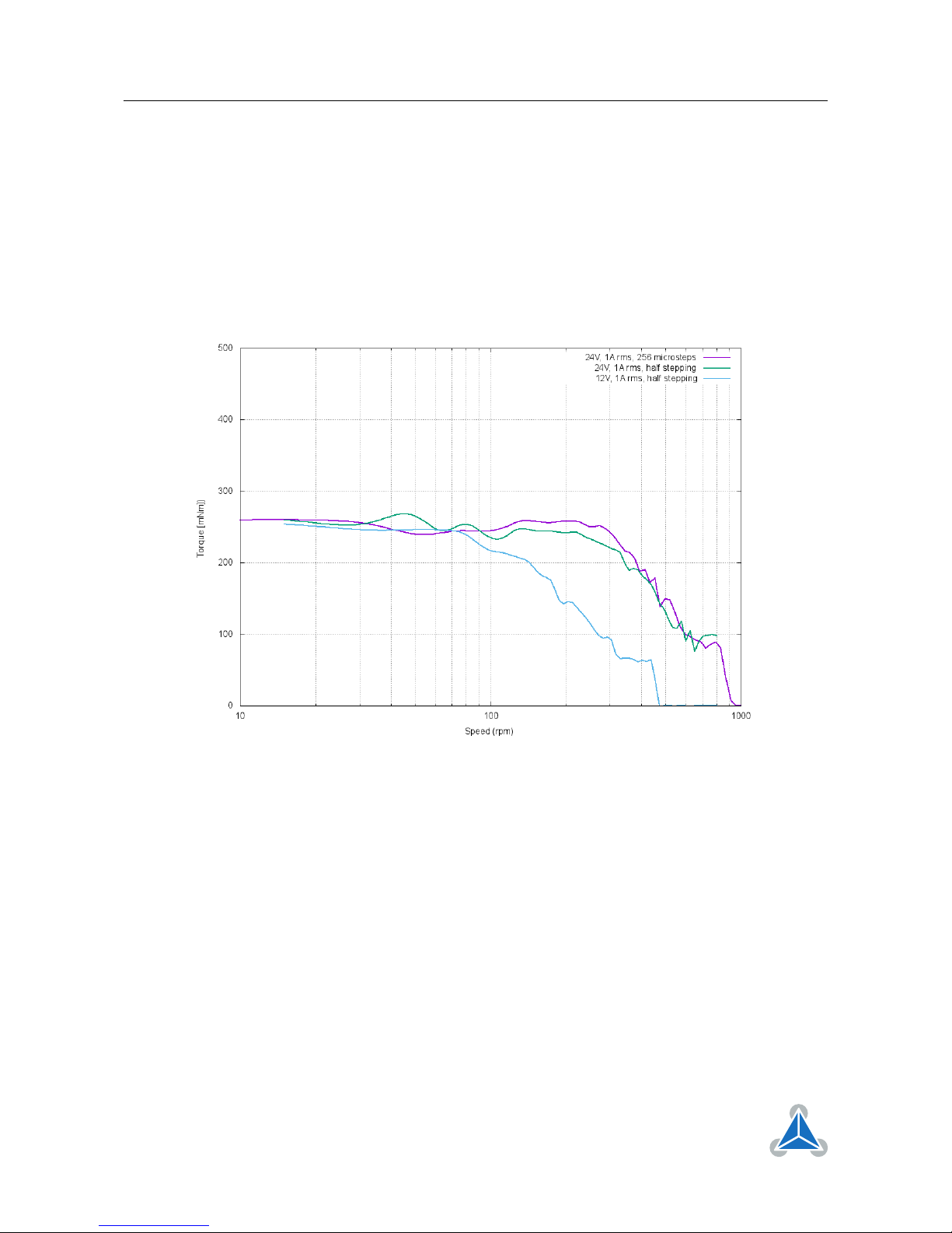
3.3 PD42-1070 Torque Curves
The following diagrams show the torque vs. speed curves for the PD42-1-1070, the PD42-2-1070, and
the PD42-3-1070 at three different typical conditions. All measurements have been done in spreadCycle
chopper mode. The measurement conditions are:
1. V DD =+24V, ICOILRMS =1A, 1/16 microstep with interpolation to 1/256 microstep
2. V DD =+24V, ICOILRMS =1A, half stepping
3. V DD =+12V, ICOILRMS =1A, half stepping
Figure 6: PD42-1-1070 torque vs. speed
©2018 TRINAMIC Motion Control GmbH & Co. KG, Hamburg, Germany
Terms of delivery and rights to technical change reserved.
Download newest version at www.trinamic.com
PD42-1070 Hardware Manual •Hardware Version V1.00 | Document Revision V1.10 •2018-July-03 10 / 25
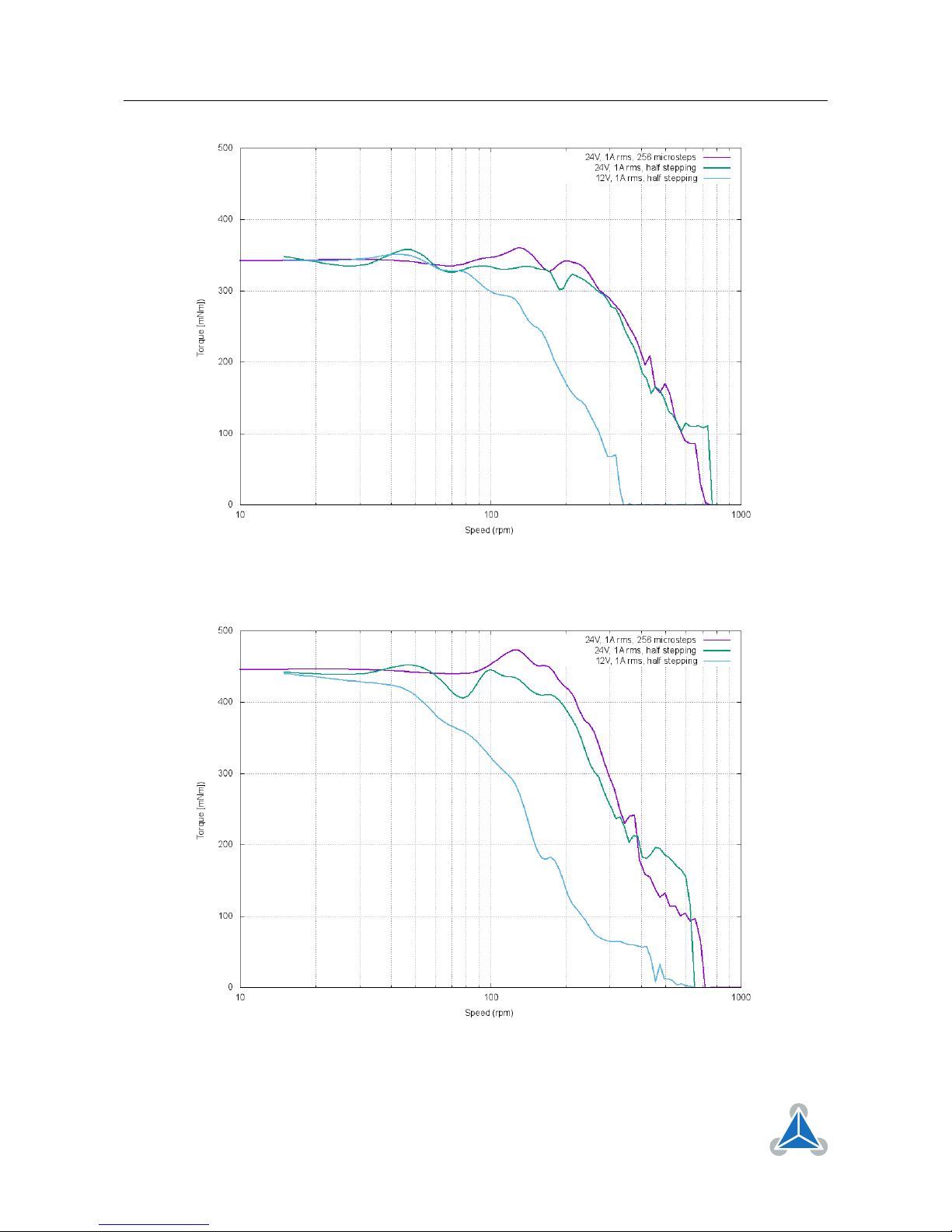
Figure 7: PD42-2-1070 torque vs. speed
Figure 8: PD42-3-1070 torque vs. speed
©2018 TRINAMIC Motion Control GmbH & Co. KG, Hamburg, Germany
Terms of delivery and rights to technical change reserved.
Download newest version at www.trinamic.com
Table of contents


