Panduit Synapsense ThermaNode EZ User manual

Cabinet Sensor Hardware Installation Manual

CABINET SENSOR HARDWARE INSTALLATION
MANUAL
1
Contents
Overview.........................................................................................................................4
About this Installation Guide............................................................................................6
Intended Audience.......................................................................................................6
Organization ................................................................................................................6
Document References.................................................................................................7
Document Conventions ...............................................................................................7
Warnings and Precautions..............................................................................................8
Getting Started................................................................................................................9
Required Hardware......................................................................................................9
Required Software.......................................................................................................9
Required Tools and Materials......................................................................................9
Installing ThermaNode EZ Cabinet Sensors.................................................................11
General Installation Guidelines..................................................................................11
Installation Process Flow...............................................................................................12
ThermaNode EZ Cabinet Sensor Kit Components........................................................13
Sensor Placement .....................................................................................................15
Installing ThermaNode EZ Cabinet Sensor Kits............................................................17
Preparing to Install ThermaNode EZs........................................................................17
Mesh Door Cabinets..................................................................................................18
Installing ThermaNode EZs with Pin Badges.........................................................18
Installing ThermaNode EZs Using Cable ties.........................................................18
Solid Door and Open Frame Cabinets.......................................................................19
Installing the ThermaNode EZ using Brackets with Adhesive Strips......................19
Installing the ThermaNode EZ Using Unistruts......................................................21
Installing ThermaNode EZs with Cable ties ..........................................................22
Dual Inlet Cabinet Configurations..............................................................................22
Validating and Commissioning the ThermaNode EZ.....................................................23

CABINET SENSOR HARDWARE INSTALLATION
MANUAL
2
ThermaNode EZ LEDs..................................................................................................25
Inspecting the Installation..............................................................................................26
Installing ThermaNode Cabinet Sensors.......................................................................27
General Installation Guidelines..................................................................................27
Installation Process Flow...............................................................................................28
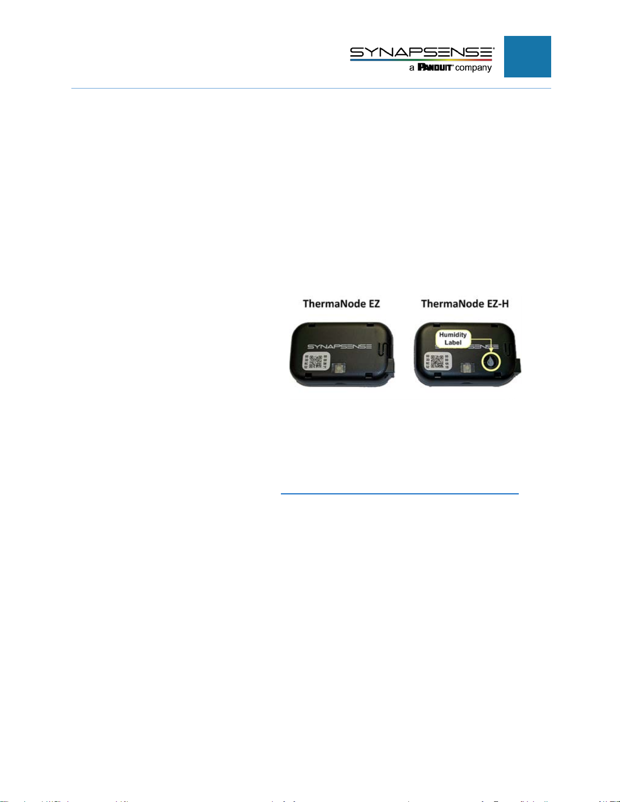
ThermaNode Cabinet Sensor Kit Components.............................................................29
Sensor Placement .....................................................................................................31
Installing ThermaNode Cabinet Sensor Kits..................................................................33
Preparing to Install ThermaNode Sensor Kits............................................................33
Mesh Door Cabinets..................................................................................................34
Installing the ThermaNode.....................................................................................34
Installing Intake Sensors........................................................................................35
Installing Exhaust Sensors.....................................................................................36
Solid or Glass Door Cabinets ....................................................................................37
Installing the ThermaNode.....................................................................................37
Installing Intake Sensors........................................................................................37
Installing Exhaust Sensors.....................................................................................38
Open Frame Cabinets ...............................................................................................39
Installing the ThermaNode.....................................................................................39
Installing Intake Sensors........................................................................................39
Installing Exhaust Sensors.....................................................................................40
Installing Top Exhaust Sensors (via Fans) ................................................................41
Installing the Subfloor Sensor (Mesh, Solid or Glass Doors, or Open Frames) .....42
Dual Inlet Cabinet Installation....................................................................................42
Dual Inlet ThermaNode Cable Assembly...............................................................42
ThermaNode and Sensor Placement.....................................................................43
Installing the Dual Inlet Cabinet Sensor Cable Assembly ......................................43
Validating and Commissioning the ThermaNode Installation........................................48
ThermaNode LEDs....................................................................................................49

CABINET SENSOR HARDWARE INSTALLATION
MANUAL
3
Inspecting the Installation..............................................................................................51
Appendix A – Common Cabinet Configurations............................................................52
Rear Exhaust.............................................................................................................52
Rear Exhaust with Subfloor.......................................................................................52
Top (Chimney)/Rear Exhaust....................................................................................53
Top (Chimney)/Rear Exhaust with Subfloor...............................................................53
Appendix B – Battery Replacement...............................................................................54
Appendix C – Environmental Monitoring System Commissioning Form........................56
FRM-007 Environmental Monitoring System.............................................................56
Appendix D – Technical Support and Return Material Authorization.............................68
Technical Support......................................................................................................68
Opening a Technical Support Case.......................................................................68
Return Material Authorization........................................................................................69
Returning SynapSense Products...........................................................................69
What Happens Next?.............................................................................................70

CABINET SENSOR HARDWARE INSTALLATION
MANUAL
4
Overview
Cabinet sensors, known as ThermaNodes, measure temperature and humidity in and
around cabinet areas and transmit collected data to the gateway. ThermaNodes also
include the ability to connect additional thermistors using various cable assemblies.
The following cabinet sensor configurations are available.
ThermaNode EZ™(wireless)
The ThermaNode EZ measures,
collects, and transmits temperature
information data to the gateway.
ThermaNode EZ-H™(wireless)
ThermaNode EZ-H (H denotes
humidity) measures and transmits
temperature and humidity data to
the gateway. The water drop on
the front label and “EH” on the
back label distinguishes the EZ-H
model.
For ThermaNode EZ Installation, see Installing ThermaNode EZ Cabinet Sensors.
N
OTE
:Throughout this document, the term ThermaNode EZ refers to the
ThermaNode EZ and ThermaNode EZ-H.

CABINET SENSOR HARDWARE INSTALLATION
MANUAL
5
ThermaNode and Sensor Cable
Assembly
The ThermaNode cable assembly
includes the ThermaNode
transceiver node, temperature-
sensing sensors, interconnect
cabling, and quick-disconnects. An
optional 36” cable extension is
also included.
These assemblies are specially
built for a variety of cabinet racks,
CRAH and CRAC units.
An optional subfloor sensor at the
end of the Exhaust Cable
Assembly measures air
temperature in subfloor areas.
For ThermaNode installation, see
Installing the ThermaNode and
Sensor Cable Assembly.
N
OTE
:The term ThermaNode refers to the seven sensor/one ThermaNode cable
assembly.

CABINET SENSOR HARDWARE INSTALLATION
MANUAL
6
About this Installation Guide
This document provides instructions for installing the ThermaNode cabinet sensors kits
provided by SynapSense to SynapSense-designated service companies or by the
customer. Cabinet sensors kits come in several different configurations, each specifically
tailored to the server cabinet configuration.
Intended Audience
The intended audience for this document includes SynapSense customers, partners, and
installers (or installation teams) who have received training from SynapSense prior to
installing the hardware detailed in this document.
SynapSense “Tier 1” training is highly recommended for installation engineers and others
who are installing cabinet sensor hardware or closely involved with the installation of data
center optimization equipment.
Organization
Table 1 summarizes the chapters and appendices of this guide.
Table 1 – Chapter and Appendix Summary
Chapter
Description
Introduction Provides an overview describing ThermaNode EZ and
ThermaNode cable assembly, and information about this guide
Getting Started Lists the hardware, software, tools, and additional material
requirements for installing SynapSense cabinet sensor kits
Installing ThermaNode EZ Cabinet
Sensors
Describes the steps to install the ThermaNode EZ cabinet sensors
Installing ThermaNode Cabinet Sensors Describes the steps to install the ThermaNode cabinet sensor
cable assembly
Appendix A – Common Cabinet
Configurations
Provides diagrams to illustrate the ThermaNode cable assembly
configurations on rear exhaust and top (chimney)/rear exhaust
cabinets.
Appendix B – Battery Replacement Provides instructions for replacing ThermaNode EZ and
ThermaNode batteries
Appendix C – Environmental
Monitoring System Commissioning
Form
Provides lists of necessary information and checklists to
commission an Environmental Monitoring System.

CABINET SENSOR HARDWARE INSTALLATION
MANUAL
7
Chapter
Description
Appendix D - Technical Support and
Return Material Authorization
Describes the process for contacting Technical Support, opening a
Support Case, and the Return Material Authorization (RMA)
process
Document References
The documents listed in this section affect the activities in this installation. Refer to the
appropriate document for user-specific information.
•SynapSense Software Installation Guide
•Web Console™User Guide
•MapSense™User Guide
•Active Control™User Guide
Document Conventions
Table 2 defines the style conventions used throughout this document.
Table 2 – Installation Guide Style Conventions
Item
Description
Bold and Blue
Denotes text that a user types, clicks, presses, or taps, for example: Click OK
NOTE:
Denotes exceptions to the rule and other important information
Denotes a warning
Denotes a safety warning of a physical or electrical nature

CABINET SENSOR HARDWARE INSTALLATION
MANUAL
8
Warnings and Precautions
The following warnings and precautions pertain to cabinet sensor installation. Failure to
adhere to warnings and precautions could result in physical injury or damage to
equipment, which may void the warranty.
Warning: When performing subfloor work in a data center, do not to stress, crush, pull, or
disconnect wiring and hoses running underneath electrical and data cables, leak detectors,
etc. (including fire alarm/suppression systems).
Warning: Subfloor work poses significant trip/fall hazards and eye hazards from airflow-
borne debris. Wear eye protection all times when removing or replacing floor tiles and
when working in or around areas with removed tiles.
Warning: Do not touch data center
electrical or computer/server equipment without
approval from data center operators (including loose cables, pushcarts, and terminals).
Safety Warning: Installation of this equipment must be in accordance with local and
national electrical codes.
Safety Warning: This product contains Lithium metal primary cell batteries, which are
NOT rechargeable. Recharging can cause battery leakage or cause the safety release vent to
open. Inadvertent charging can occur if battery installation is backwards. Dispose of
batteries appropriately after use.
Safety Warning: Lithium metal batteries may pose a fire, explosion, or burn hazard if
misused. Do not open battery, dispose of in fire, heat above 100° C (212° F), expose contents
to water, recharge, put in backwards, mix with used or other battery types as this may cause
the batteries to explode or leak and cause personal injury.
Safety Warning:
Lithium metal batteries must be properly packed and shipped in
accordance with transportation standards.
Safety Warning:
Data centers may pose a risk of hearing loss. Use appropriate ear
protection prior to entry into high-noise areas.

CABINET SENSOR HARDWARE INSTALLATION
MANUAL
9
Getting Started
Required Hardware
The required hardware for this installation is contained in the ThermaNode cabinet
sensor kits.
•ThermaNode EZ Kit Components
•ThermaNode and Sensor Cable Assembly Kit Components
Required Software
The environmental server requires the installation of the following SynapSense
software:
•Web Console
•MapSense (including optional Active Control software with MapSense project *.dlz file exported into
the Web Console)
Installation of SynapSense software takes place prior to hardware installation to prevent
redundancy of hardware verification activities. Refer to the SynapSense Software, Web
Console, and MapSense Installation Guides for more information.
Required Tools and Materials
SynapSense Field Engineers or the contracted electricians need to bring the minimum
tools and additional materials listed in Table 3 to the job site.
Table 3 – Required Tools and Materials
Item
Description/Comments
Attire Proper dress and shoes for performing work in a data center (including areas
inside the sub-floor and above ceiling tiles)
Ladder/Step Stool
To access all areas of tall server cabinets
Additional Parts
Spare Lithium metal AA batteries, sensor/cable clips, and brackets
Laptop
To configure settings (for example Modbus gateway)
Cable ties
Regular and plenum-rated cable ties
Tools Flashlight, diagonal cutters, utility knife, scissors, tile pullers, screwdrivers, torque
wrench, pliers, wire strippers, and alcohol wipes
Multi-meter
Measures voltage in power sources
Drill/Bits
Drill pilot holes for enclosure mounting
Label Maker
Create identification labels

CABINET SENSOR HARDWARE INSTALLATION
MANUAL
10
Item
Description/Comments
Barcode scanner
Use to scan ThermaNode EZ and ThermaNode MAC IDs
Digital Camera
Document wiring for troubleshooting and customer documentation purposes)
Documentation
•A printed copy of this installation document
•Web Console and MapSense User Guides
•Printed MapSense layout of the data center showing installation locations
Identification
Photo ID to present to data center security personnel

CABINET SENSOR HARDWARE INSTALLATION
MANUAL
11
Installing ThermaNode EZ Cabinet Sensors
General Installation Guidelines
Be consistent. Match all installations in appearance including node/sensor locations,
centering, wiring, and method for securing extra cable.
Be neat.
•Ensure cabling is straight and vertical or horizontal as much as possible
•Install sensors and wiring down the centerline of the doors
•Dual doors: Place sensors approximately one inch from the center-most edge of the mesh
Secure cables appropriately.
•Pull slack cable taut
•Loop and tie extra cable securely at one or more of the sensor locations to prevent dangling.
•For door loops:
•Properly size loops to prevent cable binding and pulling
•Ensure front and rear doors open fully at the same time without cable binding
•Secure loops near door hinge to allow proper door movement and cable clearance
•Secure door side loops with cable ties or cable clips one inch from disconnects
Install clips properly.
•Clean surfaces thoroughly with alcohol wipes and allow cleaned surfaces to dry
•Align clips neatly in the same direction as the wiring
•Hold clip in place for 30 seconds to ensure adhesive bonding
Use cable ties where needed.
•Attach cable ties to the inside of door such that the locking mechanism is always on the inside
•Use cable ties in adjacent holes of mesh door to keep the loop appearing on the outside as small as
possible
•Use diagonal cutters to clip cable tie ends close to its locking mechanism

CABINET SENSOR HARDWARE INSTALLATION
MANUAL
12
Installation Process Flow
Figure 1 illustrates the process flow for installing ThermaNode EZ cabinet sensors.
Figure 1 – ThermaNode EZ Cabinet Sensor Installation Process Flow

CABINET SENSOR HARDWARE INSTALLATION
MANUAL
13
ThermaNode EZ Cabinet Sensor Kit Components
The ThermaNode EZ sensor kit includes the following components:
•ThermaNode EZ
(contains two Lithium metal
AA-size batteries)
•ThermaNode EZ measures
temperature information
only
•ThermaNode EZ-H
measures temperature and
humidity. A water drop
(front) and EH on back label
(bottom) distinguishthe EZ-
H model
NOTE:Throughout this document,
the term ThermaNode EZ refers to
ThermaNode EZ and EZ-H.
•(Optional) Flexible External
Sensor collects environmental
data for installations requiring
external sensors
•Sensor Mounting Hardware
•Pin Badge for mesh door cabinet
configurations

CABINET SENSOR HARDWARE INSTALLATION
MANUAL
14
•Inserting and Removing the
ThermaNode EZ from a pin
badge:
•Pin badge mounting tabs form
a snug fit to the node mounting
grooves. Insert by snapping
the node into the mounting tabs
and seat in the mounting
grooves.
•Remove the node from the pin
badge by removing and holding
the pin badge and sliding the
node to the from side to side.
NOTE:If accidental activation occurs, turn the ThermaNode EZ off and on by
pressing and holding the ON/OFF button (shown above in blue) for five (5) seconds.
•Brackets for solid door and
open frame configurations:
•Adhesive-backed bracket
for solid doors and open
frame cabinet
configurations
•Unistrut bracket for rail
groove installation (far
right)

CABINET SENSOR HARDWARE INSTALLATION
MANUAL
15
•Connecting the Mounting
Bracket to the ThermaNode
With the node cover facing
outward, snap the node in
between the mounting tabs
on the bracket to seat the
tabs in the mounting grooves.
Sensor Placement
Sensor placement is important to ensure accurate cabinet temperature readings.
Sensors locations are at “U” levels and
continue down the centerline of the
cabinet.
This diagram illustrates common ThermaNode EZ configurations.

CABINET SENSOR HARDWARE INSTALLATION
MANUAL
16
IMPORTANT:Changing the physical location of a ThermaNode EZ also requires
changing the location in SynapSense software. Please see the instructions for relocating
a ThermaNode EZ in the Web Console User Guide 6.4, Chapter 5 – Additional Features
section.
For other cabinet configurations, including rear exhaust and top exhaust with or without
subfloors see Appendix A.

CABINET SENSOR HARDWARE INSTALLATION
MANUAL
17
Installing ThermaNode EZ Cabinet Sensor Kits
This section provides the steps for installing ThermaNode EZs on mesh door, solid
door, open frame, and dual inlet cabinet configurations. After installing the ThermaNode
cabinet sensors, see Validating and Commissioning the ThermaNode EZ Installation to
validate and commission the ThermaNode EZ. Finally, see Inspecting the Installation to
complete the installation.
NOTE:The ThermaNode EZ sensors should be installed at least 15 ft. away from the
Wi-Fi access point.
Preparing to Install ThermaNode EZs
The SynapSense Field Engineer is responsible for confirming installation readiness and
completing these steps:
1. Assure the following steps are complete:
a. Required software is installed and configured.
b. Gateways are installed and powered on.
c. All products and tools necessary for installation are on site.
2. Verify the receipt of quantities and contents listed on packing/shipping list found in
Box 1.
a. Place kits in front of each cabinet numbers on the kit bag (or as numbered on the
printed MapSense layout).
b. Verify install team has all necessary tools and additional materials to complete
installation and site is ready for installation.
3. For ThermaNodes with MAC IDs that have not yet been recorded or scanned, follow
these steps:
a. Record the ThermaNode EZ orThermaNode MAC IDs manually, or with a barcode
scanner and upload into MapSense.
b. Access the site layout from the MapSense application. Refer to the MapSense
User Guide.
c. Add and configure the appropriate ThermaNode EZ or ThermaNode objects and
associated IDs in the data center floor plan.
4. Export the MapSense project *.dlz file from MapSense for viewing in Web Console.
5. For cable assembly installations with subfloor sensors, determine where the subfloor
sensor routing will be located (rack and into the subfloor area).

CABINET SENSOR HARDWARE INSTALLATION
MANUAL
18
Mesh Door Cabinets
Use pin badges or cable ties for installations on mesh door cabinets.
Installing ThermaNode EZs with Pin Badges
1. Remove the logo faceplate from the pin badge
by turning the spring screw counter-clockwise.
2. From the inside of the door, position the node
on the door and press the spring screw through
the mesh. Position the “S” vents close to the
door centerline.
3. On theoutsideof thedoor, attach the
logo faceplate to th
e spring screw
and tighten screw. Make sure the
logo is face up.
4. Repeat the previous steps to install
the next node according to the
MapSense layout.
Proceed to Validating and
Commissioning the ThermaNode EZ
Installation.
Installing ThermaNode EZs Using Cable ties
1. Insert a cable tie through the mounting hole at each corner of the node.
2. Insert cable tie ends
through the mounting
holes/surface provided
positioning “S” vents close
to the door centerline.
3. Secure on the inside of the
cabinet.
4. Repeat the previous steps
to mount the next node.
Proceed to Validating and Commissioning the ThermaNode EZ Installation.

CABINET SENSOR HARDWARE INSTALLATION
MANUAL
19
Solid Door and Open Frame Cabinets
Use brackets with adhesive backing or Unistrut brackets to install ThermaNode EZ kits
on solid doors and open frame cabinets.
Installing the ThermaNode EZ using Brackets with Adhesive Strips
1. Clean area where
ThermaNode EZ will go and
allow to dry thoroughly.
2. Remove adhesive strip covers
from the bracket and install the
node.
•Solid door
: position “S”
vents close to the door
centerline.
•Open frame: point external
sensor connector points
toward the center of the
cabinet
3. Press firmly for 30 seconds to
ensure a secure bond.
4. Install the Bend N’ Stay for
open frame cabinet
configurations only:
•
Insert the Bend N’ Stay
external sensor into the
external sensor connector.
•
Position the Bend N’ Stay
external sensor to the
desire location. Do not bend
or exert pressure in the first
3-4 inches from the sensor
connector.
•
See the following page to
remove a Bend N’ Stay.
5.
Repeat the previous steps as
applicable to ins
tall the next
node according to the
MapSense layout.
This manual suits for next models
1
Table of contents
Other Panduit Accessories manuals