Panduit SynapSense CRAC User manual

CRAC/CRAH Sensor Installation Manual
Release 7.5.2
Issue 1

CRAC/CRAH SENSOR INSTALLATION MANUAL
1
Contents
Overview.........................................................................................................................3
About this Installation Guide............................................................................................4
Organization ................................................................................................................4
Document Conventions ...............................................................................................5
Document References.................................................................................................5
Warnings and Precautions..............................................................................................6
Getting Started................................................................................................................7
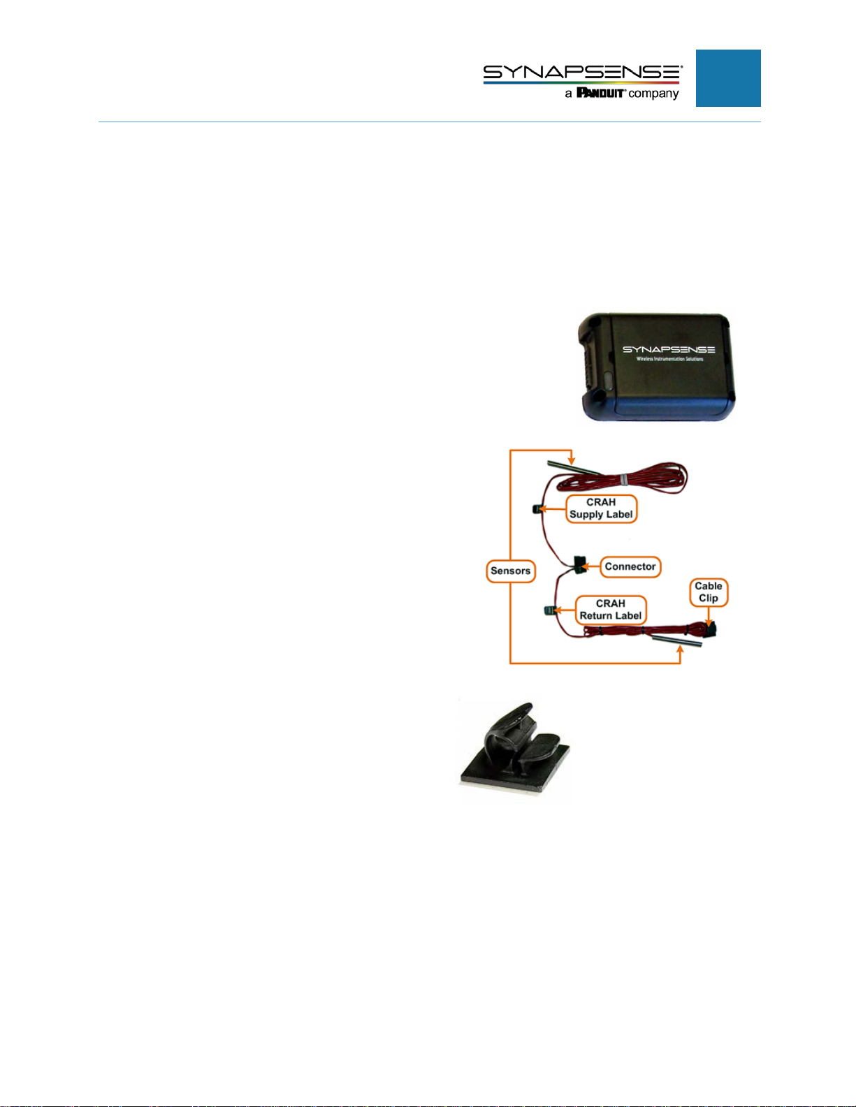
Required Hardware......................................................................................................7
Required Software.......................................................................................................7
Required Tools and Materials......................................................................................8
Installing CRAC/CRAH Sensors......................................................................................9
General Installation Guidelines....................................................................................9
Installation Process Flow...........................................................................................10
Preparing to Install the CRAC/CRAH Sensor Kits..................................................10
Installing the CRAC/CRAH Sensor Kits.....................................................................11
Initial Installation Steps ..........................................................................................11
Upflow Units...........................................................................................................12
Upflow Units with a Plenum.......................................................................................16
Downflow Units – Raised Floor..................................................................................18
Downflow Units – Floor Stand ...................................................................................21
Row (Rack) Cooling Units..........................................................................................25
Validating and Commissioning the Installation..............................................................29
ThermaNode LEDs....................................................................................................30
Inspecting the Installation..........................................................................................31
Appendix A – Battery Replacement ..............................................................................32
Appendix B – Environmental Monitoring System Commissioning Form........................33
FRM-007 Environmental Monitoring System.............................................................33

CRAC/CRAH SENSOR INSTALLATION MANUAL
2
Appendix C – Technical Support and Return Material Authorization.............................41
Technical Support........................................................ Error! Bookmark not defined.
Opening a Technical Support Case .......................................................................41
Return Material Authorization........................................................................................42
Returning SynapSense Products...........................................................................42
What Happens Next?.............................................................................................43

CRAC/CRAH SENSOR INSTALLATION MANUAL
3
Overview
CRACs and CRAHs monitor and maintain the temperature, air distribution, and humidity
in a data center. CRACs use mechanical refrigeration; CRAHs use fans, cooling coils,
and a water-chiller or glycol cooling system.
The CRAC and CRAH configurations described in this document are upflow, downflow,
and row cooling loosely based on the leading manufacturers of CRACs and CRAHs,
Liebert® and Stulz®. The diagrams and illustrations in this guide detail the general
installation of cable assemblies, sensors, and ThermaNodes for common CRAC/CRAH
configurations.

CRAC/CRAH SENSOR INSTALLATION MANUAL
4
About this Installation Guide
This document provides guidelines and instructions for installing SynapSense Pressure
Node kits to designated service companies or the customer.
The intended audience for this document includes SynapSense customers, partners, and
installers (or installation teams) who have received training from SynapSense prior to
installing the hardware detailed in this document.
SynapSense “Tier 1” training is highly recommended for installation engineers and others
who are installing cabinet sensor hardware or closely involved with the installation of
equipment for data center optimization.
Organization
This installation guide describes the tasks for installing sensor kits for CRAC/CRAH
units. Table 1 lists the chapters and appendices in this document with a short summary
describing content.
Table 1 – Chapter and Appendices Summary
Chapter
Description
Introduction Introduces this guide and lists warnings and precautions
Getting Started Lists the hardware, software, and tool and additional material
requirements for installing the CRAC/CRAH sensor kits
Installing CRAC/CRAH Sensors Provides guidelines and specific procedures for installing CRAC/CRAH
sensor kits and includes validating and inspecting the installation.
Appendix A – Battery Replacement The appendix describes ThermaNode battery replacement
Appendix B – Environmental
Monitoring System Commissioning
Form
Provides lists of necessary information and checklists to commission
an Environmental Monitoring System
Appendix C – Technical Support
and Return Material Authorization
Describes the process for contacting Technical Support, opening a
Support Case, and the Return Material Authorization (RMA) process

CRAC/CRAH SENSOR INSTALLATION MANUAL
5
Document Conventions
Table 2 defines the style conventions used throughout this document.
Table 2 – Installation Guide Style Conventions
Item
Description
Bold and Blue Used for anything a user types, clicks, presses, or taps For example, Click OK.
NOTE:
Exceptions to the rule and other important information
Denotes a warning
Denotes a safety warning of a physical or electrical nature
Document References
The documents listed in this section affect the activities in this document. Refer to the
appropriate document for user-specific information.
•SynapSense Software Installation Guide
•Web Console™ User Manual
•MapSense™ User Manual
•Active Control™ User Manual
•Active Control™ Installation Guide

CRAC/CRAH SENSOR INSTALLATION MANUAL
6
Warnings and Precautions
The following warnings and precautions pertain to the CRAC/CRAH sensor installation.
Failure to adhere to warnings and precautions could result in physical injury or damage
to equipment, which may void the warranty.
Warning: When performing subfloor work in a data center, be careful not
to stress, crush, pull, or disconnect wiring and hoses running underneath
electrical and data cables, leak detectors, etc. (including fire
alarm/suppression systems).
Warning: Subfloor work poses significant trip/fall hazards and eye
hazards from airflow-
borne debris. Eye protection must be worn at all
times when removing or replacing floor tiles and when working in or
around areas with removed tiles.
Warning: Do not touch any data center electrical or computer/server
equipment without approval from data center operators (including loose
cables, pushcarts, and terminals).
Safety Warning: Installation of this equipment must be in accordance
with local and national electrical codes.
Safety Warning: This product contains Lithium metal primary cell
batteries, which are NOT rechargeable. Recharging can cause battery
leakage or cause the safety release vent to open. Inadvertent charging
can occur if battery installation is backwards.
Dispose of batteries
appropriately after use.
Safety Warning: Lithium metal batteries may pose a fire, explosion, or
burn hazard if misused. Do not open battery, dispose of in fire, heat above
100° C (212° F), expose contents to water, recharge, put in backwards,
mix with used or other battery types as this may cause the batteries to
explode or leak and cause personal injury.
Safety Warning: Lithium metal batteries must be properly packed and
shipped in accordance with transportation standards.
Safety Warning: Data centers may pose a risk of hearing loss. Use
appropriate ear protection prior to entry into high-noise areas.

CRAC/CRAH SENSOR INSTALLATION MANUAL
7
Getting Started
Required Hardware
The required hardware for this installation is contained in the CRAC/CRAH sensor kits.
CRAC/CRAH Sensors installation kits contain:
•ThermaNode:
−Transmits data from cable assembly sensors and to the gateway
−Contains four AA-size batteries
−Contains a pin plug that accepts sensor assemblies
•CRAC/CRAH Cable Assembly:
ThermaNodes connect to a 2-sensor cable assembly
that measures return and supply air temperature and
humidity. The cable assembly includes:
−Plenum-rated material
−Return and supply wires measuring 10’ in length
−Stainless steel sensors
−Labels for supply and return wires
•Adhesive-backed cable clips
•Regular and plenum-rated (purple) zip ties (not shown)
•3M Command Strips™ (not shown)
Required Software
The environmental server requires the installation of the following SynapSense
software:
•Web Console™

CRAC/CRAH SENSOR INSTALLATION MANUAL
8
•MapSense™ (including optional Active Control™ software with MapSense project *.dlz file exported
into the Web Console)
Installation of SynapSense software generally takes place prior to hardware installation,
which prevents redundancy of hardware verification activities. Refer to the SynapSense
Software, Web Console, and MapSense Installation and User Guides for more
information.
Required Tools and Materials
Table 3 lists the minimum tool and material requirements installers need to bring to the
job site.
Table 3 – Required Tools and Materials
Item Description/Comments
Attire Proper dress and shoes for performing work in a data center (including areas
inside the sub-floor and above ceiling tiles)
Ladder/Step Stool To access all areas of the CRAC/CRAH units
Additional Parts Spare ThermaNodes and batteries
Laptop To configure settings (for example Modbus gateway)
Fasteners Regular and plenum-rated zip ties, cable clips, and mounting brackets
Tools
7/32” Allen wrench, flashlight, diagonal cutters, utility knife, scissors, tile
pullers, thin blade screwdrivers, torque wrench, pliers, wire strippers, and
alcohol wipes
Multi-meter Measures voltage in power sources
Label Maker Create identification labels
Barcode scanner Use to scan ThermaNode MAC IDs
Documentation
•A printed copy of this installation document
•Web Console and MapSense User Guides
•Printed MapSense layout of the data center showing installation locations
Identification Photo ID to present to data center security personnel

CRAC/CRAH SENSOR INSTALLATION MANUAL
9
Installing CRAC/CRAH Sensors
General Installation Guidelines
Ensure software installation and required file exports before installing hardware
Be consistent. Match all installations in appearance including node/sensor locations,
centering, wiring, and method for securing extra cable
Be neat.
•Ensure wiring is straight and vertical or horizontal as much as possible
•Follow the existing wire bundle path of the CRAC/CRAH where possible
Secure wires appropriately.
•Pull slack wire taut
•Loop extra wire and tie securely at one or more of the sensor locations to prevent wiring from
dangling or moving
Install clips properly.
•Clean surfaces thoroughly with alcohol wipes and allow cleaned surfaces to dry
•Align clips neatly (vertical or horizontal) in the same direction as wiring
•Hold clip in place for 30 seconds to ensure adhesive bonding
Use Zip Ties where needed.
•Pull wire(s) taut to prevent slippage but not so tight to cause pinched wiring
•Use diagonal cutters to clip zip tie ends close to its locking mechanism
•Use fire code compliant, plenum-rated (usually purple) zip ties to secure cable assembly and
sensor wire to the CRAC/CRAH stand
•Follow all site safety procedures and protocols
Safety Warning: HIGH VOLTAGE! Most CRACs and CRAHs are 3-
phase, which can cause electric shock possibly resulting in injury or
death.
Safety Warning: Ensure Facilities Supervisor or designee disconnects
local and remote power supplies before starting sensor installation work.
Safety Warning: Contact with moving parts, such as fans, could cause
injury or death.
Safety Warning: Ensure Facilities Supervisor or designee disconnects
all local and remote electric power supplies before starting sensor
installation work.

CRAC/CRAH SENSOR INSTALLATION MANUAL
10
Safety Warning: Contact with hot surfaces can cause burns.
Safety Warning: Ensure Facilities Supervisor or designee allowed
sufficient time for cooling before starting sensor installation work.
Safety Warning: Report unsafe conditions (leaks, hot surfaces,
exposed wiring, etc.) to the Facilities Supervisor or designee for
correction prior to starting installation work.
Safety Warning: Wear appropriate personal protection equipment such
as gloves, safety glasses, and safety shoes (as required) before starting
sensor installation work.
Safety Warning: CRAC/CRAH panels can weigh in excess of 35
pounds. Use proper lifting techniques (for example, 2-person lift) to
prevent injury.
Installation Process Flow
Figure 1 shows the procedural flow for installing CRAC/CRAH Sensors.
Figure 1 – CRAC/CRAH Sensor Installation Process Flow
Preparing to Install the CRAC/CRAH Sensor Kits
The SynapSense Field Engineer is responsible for completing these steps to confirm
installation readiness:
1. Assure the following steps are complete:
−Installation and configuration of required software
−Installation and power on for all gateways
−All products and tools necessary for installation are on site
2. Verify the receipt of quantities and contents listed on packing/shipping list found in Box 1.

CRAC/CRAH SENSOR INSTALLATION MANUAL
11
3. Place kits in front of each cabinet numbers on the kit bag (or as numbered on the printed MapSense
layout).
4. For ThermaNodes with MAC IDs that have not yet been recorded or scanned, follow these steps:
a. Record the ThermaNode MAC IDs manually, or with a barcode scanner and upload into
MapSense.
b. Access the site layout from the MapSense application. Refer to the MapSense User Guide.
c. Add and configure the appropriate ThermaNode objects and associated IDs in the data center
floor plan.
5. Export the MapSense project *.dlz file from MapSense for viewing in Web Console.
6. Review required safety precautions and procedures specific to the site (for example, lockout/tagout
[LOTO] procedures, CRAC/CRAH power down procedures, etc.)
7. Ensure CRAC/CRAH power is off and energy dissipated from unit.
8. Customer has completed all preinstall activities such as facilities, required electric work by qualified
electrician, server installation, and alarm deactivations.
9. Wear the appropriate personal protection equipment for the installation (for example, safety glasses).
10. Ensure Facilities Supervisor disabled alarms connected to the CRAC/CRAH or Row Cooling unit.
11. Ensure power to the CRAC/CRAH or Row Cooling unit is off and energy dissipated. Use a multi-
meter to verify energy dissipation.
12. Ensure unit is cool to the touch.
13. For installations with a raised floor, remove the necessary floor tiles to access subfloor area
Installing the CRAC/CRAH Sensor Kits
This section provides the steps for installing the CRAC/CRAH sensor kits.
After installation, refer to the Validating and Commissioning the ThermaNode
Installation section to validate and commission the installation. Then proceed to
Inspecting the Installation to complete the installation process.
Initial Installation Steps
For all CRAC/CRAH or row (rack) cooling sensor kit installations, complete the following
activities.
NOTE:The ThermaNode Sensor should be installed at least 15 ft. away from the Wi-Fi
access point.

CRAC/CRAH SENSOR INSTALLATION MANUAL
12
Warning: To avoid condensation and battery corrosion within the nodes, DO NOT
install the ThermaNode in the supply area of a CRAC or CRAH unit!
1. Open access panels and holes.
a. Remove or open the necessary access panels using an Allen wrench and set aside.
b. Investigate the location of the unit access holes for cable routing (where applicable).
2. Assemble the CRAC/CRAH Cable Assembly
a. Determine the best location for the ThermaNode installation in the unit filter (return) area.
b. Remove filter from unit per manufacturer’s instructions to expose the mounting rim in the filter
area or the mounting rim in the plenum area (if necessary and applicable).
c. Separate the sensor strands in the cable assembly.
3. Determine gateway density of no more than 200 nodes per gateway.
NOTE: The illustrations in the following sections represent a generalization for wire
routing and present only one method. Other wire routing methods are
acceptable provided they meet installation guidelines and requirements.
Exaggeration of the space inside the unit interior is for clarity purposes only and
not indicative of the actual space available.
Continue with the following sections to install CRAC/CRAH sensor kits to the following
CRAC/CRAHs:
•Upflow Units
•Upflow Units with a Plenum
•Downflow Units – Raised Floor
•Downflow Units – Floor Stand
•Row (Rack) Cooling
Upflow Units
The return (hot) air enters through the sides (front or back) of the CRAC/CRAH units and
discharges through the top (front or back) (Figure 2) or through a plenum (Figure 3).
Consult with the plenum manufacturer’s operation manual to determine the best location
for installing the sensors.
In this installation:
•Sensors installations are always in the airflow path
•Return sensors are always where the return (hot) air enters
•Supply sensors install where the supply (cold) air exits
•The ThermaNode installs in the same approximate location as the return wire and sensor

CRAC/CRAH SENSOR INSTALLATION MANUAL
13
Warning: To avoid condensation and battery corrosion within the nodes,
DO NOT install the ThermaNode in the supply area of a CRAC or CRAH
unit!
Figure 2 – Upflow CRAC/CRAH Configuration – Front Return/Top Supply
Figure 3 – Upflow CRAC/CRAH Configuration – Front Return/Front Plenum Supply
Follow these steps to install a sensor kit in an upflow CRAC/CRAH unit.

CRAC/CRAH SENSOR INSTALLATION MANUAL
14
1. Route and install the supply sensor to the
filter area.
a. Route the supply sensor wire along the
mounting rim in the filter area.
b. Secure the supply wire with a cable clip,
allowing the sensor to hang over the
mounting rim in the supply airflow path.
c. Route the supply wire to the corner filter
area using cable clips as needed along
the mounting rim of the filter.
2. Route the supply wire to the unit to follow
the path of existing wires in the unit.
a. Secure the supply wire to unit wiring
with zip ties
b. Leave enough length in the supply wire
for the ThermaNode installation.
3. Route and install the return sensor.
a. Route the return sensor and return wire
to a return air vent (front or back).
b. Secure the return wire with zip ties,
allowing the sensor to hang in the return
airflow path.
c. Secure the return wire down the
centerline of the return air vent with zip
ties to, or near, the bottom of the unit.

CRAC/CRAH SENSOR INSTALLATION MANUAL
15
4. Route the return wire in the unit.
a. Route the return wire from the return air
vent areas to join the supply wire and
existing wires in the unit.
b. Secure the return wire with zip ties to the
unit wiring, leaving enough length for the
ThermaNode installation.
5. Mount the ThermaNode.
a. Clean the ThermaNode installation area (in the
return area) with alcohol wipes. Allow area to dry.
b. Attach 3M Command Strips to the underside of
the ThermaNode (if not already present).
6. Plug the cable assembly connector into the
ThermaNode.
7. Temporarily install the unit with the
ThermaNode LED facing toward the open area
(ON/OFF switch accessible).

CRAC/CRAH SENSOR INSTALLATION MANUAL
16
8. Secure excess wiring.
a. Bundle and secure excess wiring with zip ties.
b. Secure bundle to existing wires in the unit.
Continue to Validating and Commissioning the Installation.
Upflow Units with a Plenum
1. Route and install the supply sensor and wire to a selected location in the plenum area, which may
include routing the sensor and wire through an access hole in the plenum wall or bottom plate.
a. Install the supply sensor and wire
to the plenum grill (front or back),
and secure to the grill with zip
ties. If the plenum does not have
a grill, uses cable clips on the
plenum wall.
b. Ensure the sensor hangs in the
supply airflow path.
c. Secure the supply wire to the
plenum grill or wall using zip ties
or cable clips as needed.
d. Secure the supply sensor to the
mounting rim with cable clips.
2. Route the supply wire to the unit to
follow the path of existing wires in the
unit.
a. Secure the supply wire to unit
wiring with zip ties
b. Leave enough length in the
supply wire for the ThermaNode
installation.
3. Route and install the return sensor.
a. Route the return sensor and return wire
to a return air vent (front or back).

CRAC/CRAH SENSOR INSTALLATION MANUAL
17
b. Secure the return wire with zip ties
allowing the sensor to hang in the
return airflow path.
c. Secure the return wire down the return
air vent with zip ties to, or near, the
bottom of the unit.
4. Route the return wire in the unit.
a. Route the return wire from the return area to join
the supply wire and existing wires in the unit.
b. Secure the return wire with zip ties to the unit
wiring, leaving enough length for the ThermaNode
installation.
5. Mount the ThermaNode.
a. Clean the ThermaNode installation area (in the
return area) with alcohol wipes. Allow area to dry.
b. Attach 3M Command Strips to the underside of the
ThermaNode (if not already present).
6. Plug the cable assembly connector into the
ThermaNode.
7. Temporarily install the unit with the ThermaNode
LED facing toward the open area (ON/OFF switch
accessible).

CRAC/CRAH SENSOR INSTALLATION MANUAL
18
8. Secure excess wiring.
d. Bundle and secure excess wiring with zip ties.
e. Secure bundle to existing wires in the unit.
Continue to Validating and Commissioning the
Installation.
Downflow Units – Raised Floor
Figure 4 shows a downflow CRAC/CRAH installed on a raised floor with a
stand on the subfloor supporting the unit.
The return air (hot) enters the top of the CRAC/CRAH (or via optional
plenums – not shown) where the cooled air discharges through the bottom of
the unit.
The supply sensor installs through a hole in the bottom of the unit and
secures to the leg of the stand with a plenum-rated, fire-code-compliant zip
tie.
Figure 4 – Downflow CRAC/CRAH with Raised Floor/Subfloor Configuration
Follow these steps to install a sensor kit in a downflow CRAC/CRAH unit with a raised
floor/subfloor.

CRAC/CRAH SENSOR INSTALLATION MANUAL
19
1. Route and install the supply sensor.
a. Locate and route the supply
sensor and wire through the
bottom.
b. Feed the supply sensor and
wire through the prepared hole
in the raised floor tile beneath
the unit.
c. Pull the supply wire through the
hole in the floor tile and into the
subfloor area, making sure wire
does not catch or rub against
sharp edges.
d. Secure the supply sensor and
wire to the stanchion of the
raised floor frame with a
plenum-rated zip tie.
The sensor position must be no lower than 4
inches above the subfloor and 4 inches below
the raised floor tile.
2. Route the supply wire in the unit.
a. Route and secure the supply wire to
follow the path of existing wires in the
unit using zip ties to secure the supply
wire to the unit wiring.
b. Continue routing the supply wire to the
corner of the unit and up the unit wall,
securing the wire with cable clips as
needed.
c. Route the supply wire on the mounting
rim, securing with cable clips as needed,
leaving enough supply wire length to
mount the ThermaNode.
Other manuals for SynapSense CRAC
1
This manual suits for next models
1
Table of contents
Other Panduit Accessories manuals