DPOE™ Power System User Manual Part Number: PN380C
iv
TABLE OF CONTENTS
SAFETY WARNING ..................................................................................................................... ii
FCC Compliance Statement ..................................................................................................... ii
WARRANTY ................................................................................................................................. ii
TRADEMARKS ........................................................................................................................... iii
OVERVIEW...................................................................................................................................1
INSTALLATION............................................................................................................................2
Package Contents.....................................................................................................................2
Heat Dissipation........................................................................................................................3
AC Input Wiring.........................................................................................................................3
DC Output Wiring Sizing ...........................................................................................................4
Connecting to a DPoE™ Power Patch Panel or Compact 8 Midspan .................. 5
Torque Settings.........................................................................................................................7
Required Tools..........................................................................................................................7
Site and Equipment Preparation ...............................................................................................7
POWER PLANT MOUNTING AND WIRING................................................................................8
Mechanical Mounting ................................................................................................................8
Support Shelf Mounting (Optional)............................................................................................8
AC Input ....................................................................................................................................9
DC Output .................................................................................................................................9
TEST AND TURN-ON ................................................................................................................11
Rectifiers .................................................................................................................................11
Power Up ................................................................................................................................11
Short Circuit and Current Limit................................................................................................11
TROUBLESHOOTING ...............................................................................................................12
Figures
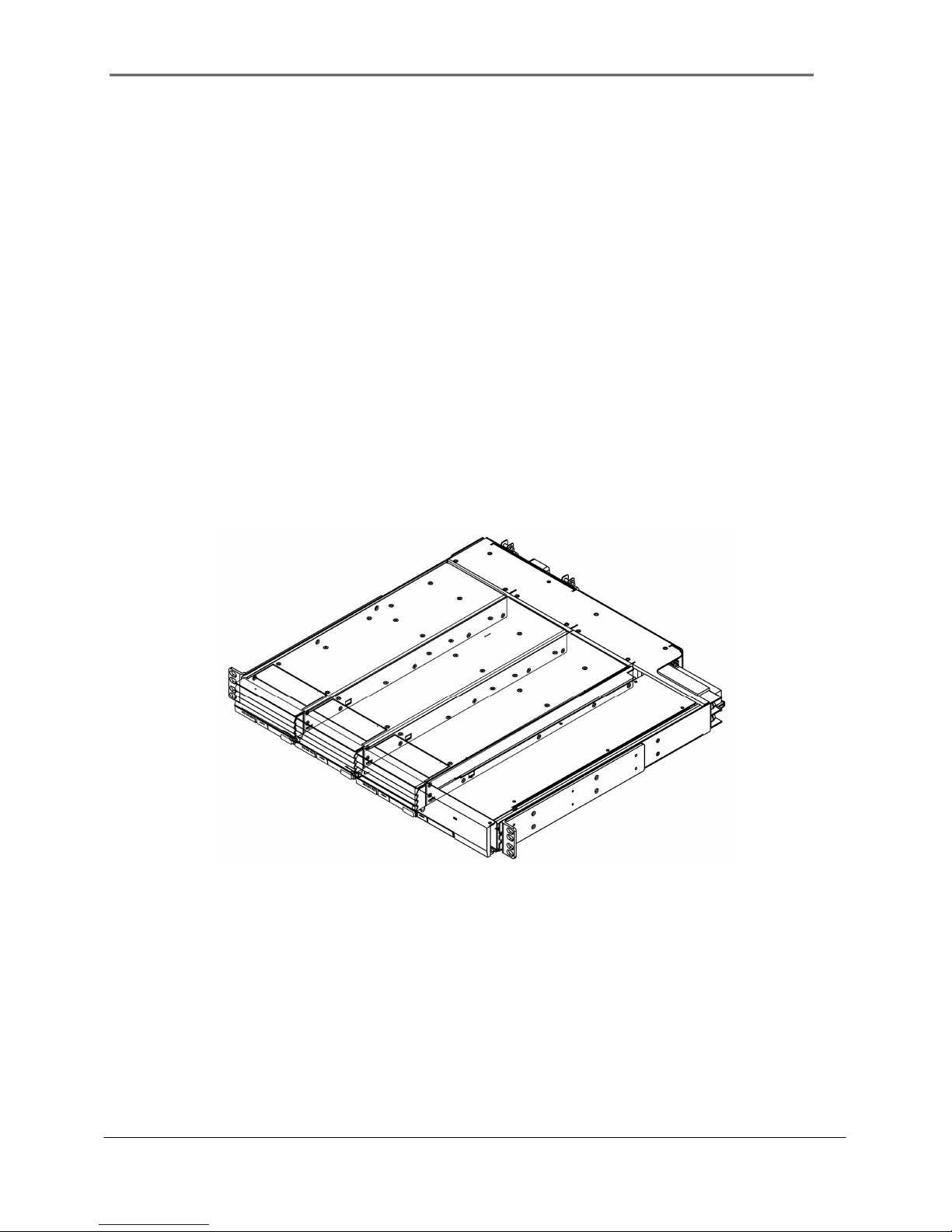
Figure 1 : Top View of Power Chassis with Power Rectifiers Installed.........................................1
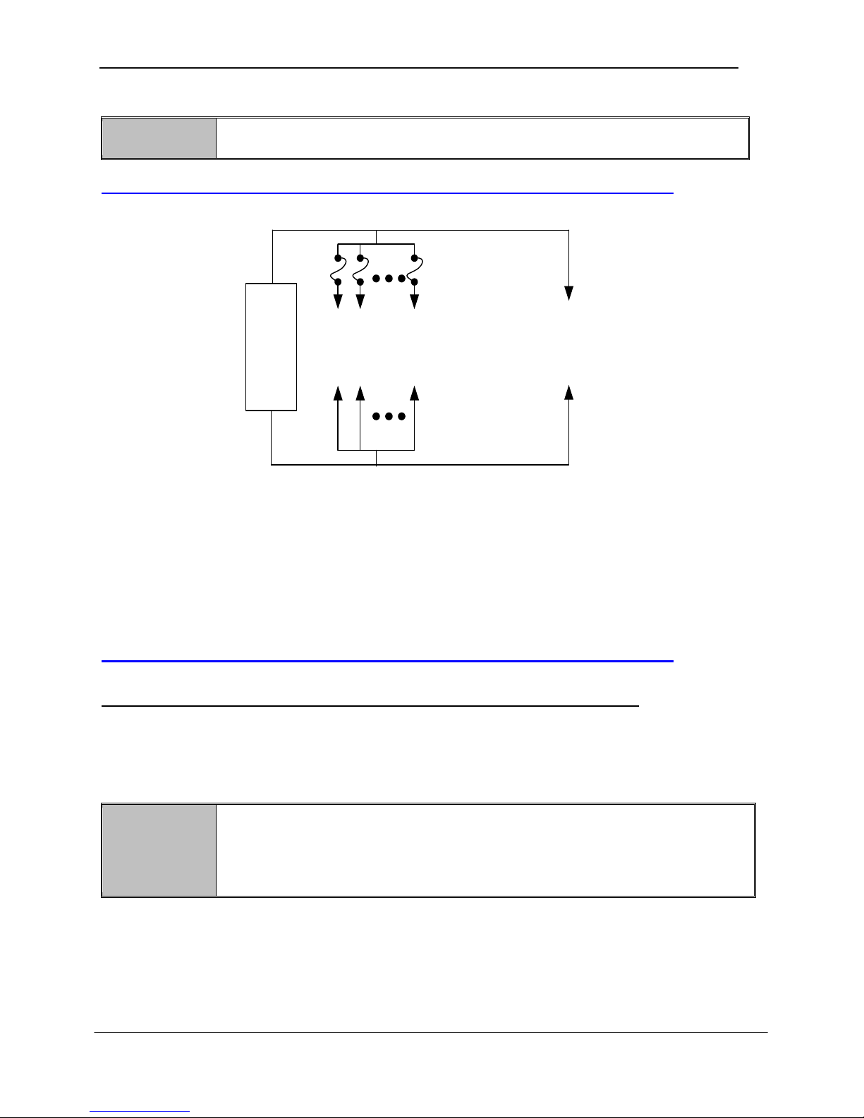
Figure 2: Individual AC Feed Wiring Architecture .........................................................................4
Figure 3: DC Wire Diagram...........................................................................................................5
Figure 4: Connecting to a DPoE™ Power Patch Panel or Compact 8 Midspan...........................6
Figure 5: Chassis (Front View) .....................................................................................................8
Figure 6: Optional Rack Mount Shelf ............................................................................................8
Figure 7: Cord Bracket..................................................................................................................9
Figure 8: Chassis (Rear View) - AC Connections.........................................................................9
Figure 9: Securing Cord Bracket to Chassis.................................................................................9
Figure 10: Chassis (Front View) - GMT fuse holder ...................................................................10
Figure 11: GMT 7.5A DC Power Fuse ........................................................................................10
Figure 12: Chassis (Rear View) - DC Connections.....................................................................10
Figure 13: Installing or Removing Rectifiers ...............................................................................11
List of Tables
Table 1: Package Contents...........................................................................................................2
Table 2: DPOE™ Power Components Available from PANDUIT..................................................3
Table 3: Heat Dissipation..............................................................................................................3