PANHANS 334|20 User manual

TRANSLATION OF THE ORIGINAL VERSION
HOKUBEMA Maschinenbau GmbH
Graf-Stauffenberg-Kaserne, Binger Str. 28 | Halle 120
DE 72488 Sigmaringen | Tel. +49 07571 755-0
E-Mail: info@hokubema-panhans.de | Web: https://hokubema-panhans.de
Operating Manual
Surface Planers and Jointers
PANHANS Types 334|20, 335|20 and 336|20
Machine Types:
334|20
335|20
336|20

BA_PH_335-20_EN_07-22.docx
2
Table of Contents
1Introduction.................................................................................................................................................... 6
1.1 Legal Notice ........................................................................................................................................... 6
1.2 Illustrations............................................................................................................................................ 6
2Symbols .......................................................................................................................................................... 6
2.1 General Symbols.................................................................................................................................... 6
2.2 Symbols in Safety Instructions............................................................................................................... 7
3General ........................................................................................................................................................... 8
3.1 Target Group and Previous Experience ................................................................................................. 8
3.2 Requirements for the Operators ........................................................................................................... 8
3.3 Accident Prevention .............................................................................................................................. 8
3.4 General Safety Regulations ................................................................................................................... 9
3.5 Structure and Function........................................................................................................................ 10
3.6 Advantages & Special Features of the Machine.................................................................................. 10
3.7 Standard Equipment............................................................................................................................ 11
3.8 Available Options................................................................................................................................. 11
4Safety............................................................................................................................................................ 12
4.1 Basic Safety Instructions...................................................................................................................... 12
4.1.1 Application Area and Intended Use............................................................................................................. 12
4.1.2 Modifications and Conversions to the Machine.......................................................................................... 12
4.1.3 Residual Risks .............................................................................................................................................. 13
4.2 Observe the Environmental Protection Regulations ........................................................................... 14
4.2.1 Organisational Measures............................................................................................................................. 14
4.2.2 Personnel Selection and Qualification - Basic Duties .................................................................................. 14
4.3 Safety Instructions for Specific Phases of Operation........................................................................... 15
4.3.1 Normal Operation ....................................................................................................................................... 15
4.3.2 Special work within the Scope of Maintenance Work as well as Troubleshooting in the Workflow .......... 16
4.3.3 Safe Working Practices................................................................................................................................ 16
4.4 Hazardous Areas.................................................................................................................................. 17
4.4.1 Working Areas & Protective Measures ....................................................................................................... 17
5Machine Data ............................................................................................................................................... 18
5.1 Technical Specifications....................................................................................................................... 18
5.2 Technical Features............................................................................................................................... 18
5.3 Emission Levels .................................................................................................................................... 19
5.3.1 Noise Information ....................................................................................................................................... 19
5.3.2 Noise Emission Values................................................................................................................................. 19
6Dimensions................................................................................................................................................... 20
6.1 Front & Top View................................................................................................................................. 20

BA_PH_335-20_EN_07-22.docx
3
6.2 Side View ............................................................................................................................................. 21
7Installation and Connection ......................................................................................................................... 22
7.1 Check Delivery Conditions ................................................................................................................... 22
7.2 Transport ............................................................................................................................................. 22
7.3 Installing the Machine ......................................................................................................................... 22
7.4 Temporary Storage.............................................................................................................................. 23
7.5 Lashing on a Transport Vehicle............................................................................................................ 23
7.6 Connecting the Extraction Unit ........................................................................................................... 24
7.7 Electrical Connections ......................................................................................................................... 25
7.8 Backup Fuse......................................................................................................................................... 25
7.9 Supply Cable ........................................................................................................................................ 25
7.10 Machine Socket (Option)..................................................................................................................... 25
7.11 Attachment of Auxiliary Equipment .................................................................................................... 25
8Components and Controls............................................................................................................................ 26
8.1 Machine Components ......................................................................................................................... 26
8.2 Control Panel “Surface Planing & Jointing” (Details)........................................................................... 27
9Commissioning ............................................................................................................................................. 28
9.1 Switching the Machine ON and OFF.................................................................................................... 28
9.1.1 Switching ON ............................................................................................................................................... 28
9.1.2 Switching OFF.............................................................................................................................................. 28
10 Machine Operation ...................................................................................................................................... 29
10.1 Electrical Chip Removal Adjustment.................................................................................................... 29
10.2 Hollow and Pointed Joint Adjustment................................................................................................. 29
10.2.1 Calibrate Hollow and Pointed Joint on the Digital Indicator ....................................................................... 29
10.3 Adjusting the Outfeed Table................................................................................................................ 30
10.4 Operating the Fence ............................................................................................................................ 31
10.4.1 Linear Adjustment ....................................................................................................................................... 31
10.4.2 Angular Adjustment up to 35°..................................................................................................................... 31
10.4.3 Angular Adjustment > 35° ........................................................................................................................... 32
10.4.4 Using the Auxiliary Fence ............................................................................................................................ 32
10.4.5 Push Block & Push Handle........................................................................................................................... 32
10.5 Planer Guard TXF 1570 ........................................................................................................................ 33
10.5.1 Flat Planing .................................................................................................................................................. 33
10.5.2 Edge Jointing ............................................................................................................................................... 33
10.6 Optional Planer Guards SUVAMATIC & TX MATIC............................................................................... 33
11 Calibrating the Digital Indicator ................................................................................................................... 34
11.1 Calibrate Chip Removal ....................................................................................................................... 34
11.2 Calibrating Angles for Hollow and Pointed Joints................................................................................ 35
12 Changing the Planer Knives .......................................................................................................................... 36

BA_PH_335-20_EN_07-22.docx
4
12.1 Changing the TERSA Knives on an All-Steel Cutter Block (standard)................................................... 36
12.2 Changing the Knives on PANHANS Traditional Cutter Block (Option)................................................. 37
12.2.1 PANHANS Cutter Block Adjusting Devices................................................................................................... 37
12.2.2 Magnetic Quick Adjusters 1533 (Option) .................................................................................................... 38
12.3 Changing the Knives on PANHANS Spiral Cutter Block (Option) ......................................................... 39
12.3.1 Procedure for Changing the Knives ............................................................................................................. 39
12.3.2 Advantages of the PANHANS Spiral Cutter Block ........................................................................................ 39
13 Troubleshooting ........................................................................................................................................... 40
14 Maintenance and Inspection........................................................................................................................ 41
14.1 Lubrication Instructions....................................................................................................................... 41
14.2 Readjust Motor Brake.......................................................................................................................... 42
14.2.1 Checking the Adjustment ............................................................................................................................ 42
14.2.2 Replace Motor Brake................................................................................................................................... 42
14.3 Tighten / Replace the V-Belt................................................................................................................ 43
15 Options and Accessories .............................................................................................................................. 44
15.1 Cutter Blocks and Planing Knives......................................................................................................... 44
15.1.1 Accessories for Tersa Cutter Blocks (Standard ............................................................................................ 44
15.1.2 Accessories for Spiral Cutter Block (Option)................................................................................................ 44
15.1.3 Accessories for Spiral Cutter Block (Option)................................................................................................ 45
15.2 Planer Guards ...................................................................................................................................... 45
15.3 Special Accessories .............................................................................................................................. 45
16 Disassembly and Scrapping .......................................................................................................................... 46
EU - Declaration of Conformity ............................................................................................................................. 47

BA_PH_335-20_EN_07-22.docx
5
List of Figures
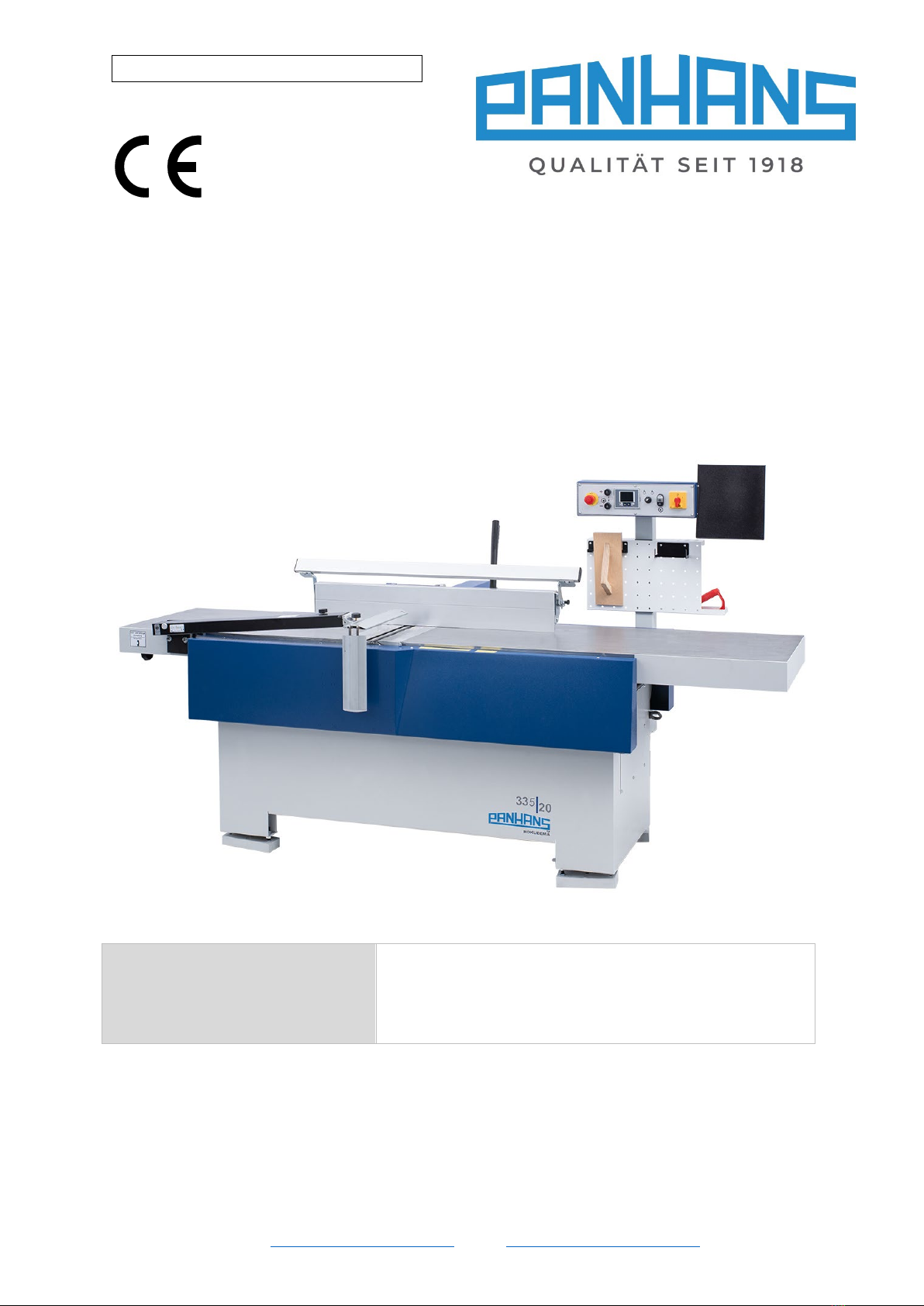
Figure 1: Surface planer & jointer 335|20 .............................................................................................................. 6
Figure 2: Danger zones.......................................................................................................................................... 17
Figure 3: Nameplate.............................................................................................................................................. 18
Figure 4: Working area.......................................................................................................................................... 19
Figure 5: Dimensions top & side view................................................................................................................... 20
Figure 6: Dimensions side view............................................................................................................................. 21
Figure 7: Transportation ....................................................................................................................................... 22
Figure 8: Adjustable underlay ............................................................................................................................... 22
Figure 9: Lashing points ........................................................................................................................................ 23
Figure 10: Connection to an extraction unit ......................................................................................................... 24
Figure 11: Electrical connection............................................................................................................................ 25
Figure 12: Console for auxiliary equipment .......................................................................................................... 25
Figure 13: Components & controls (front view) ................................................................................................... 26
Figure 14: Control panel “surface planing & jointing” .......................................................................................... 27
Figure 15: Control panel with main switch ........................................................................................................... 28
Figure 16: Chip removal ........................................................................................................................................ 29
Figure 17: Hollow / pointed joint adjustment....................................................................................................... 29
Figure 18: Outfeed table handwheel .................................................................................................................... 30
Figure 19: Clamping lever for fence ...................................................................................................................... 31
Figure 20: Linear adjustment of the fence ............................................................................................................ 31
Figure 21: Activate angular adjustment................................................................................................................ 31
Figure 22: Adjusting angles ................................................................................................................................... 31
Figure 23: Auxiliary fence...................................................................................................................................... 32
Figure 24: Push block & push handle.................................................................................................................... 32
Figure 25: Planer guard TXF 1570 ......................................................................................................................... 33
Figure 26: Guard setting for flat planing............................................................................................................... 33
Figure 27: Guard setting for edge jointing ............................................................................................................ 33
Figure 28: Type SUVAMATIC (example) ................................................................................................................ 33
Figure 29: Calibrate chip removal 1 ...................................................................................................................... 34
Figure 30: Calibrate chip removal 2 ...................................................................................................................... 34
Figure 31: Calibrate chip removal 3 ...................................................................................................................... 34
Figure 32: Calibrate chip removal 4 ...................................................................................................................... 34
Figure 33: Calibrate angle 1 .................................................................................................................................. 35
Figure 34: Calibrate angle 2 .................................................................................................................................. 35
Figure 35: Calibrate angle 3 .................................................................................................................................. 35
Figure 36: Calibrate angle 4 .................................................................................................................................. 35
Figure 37: Changing Tersa knives.......................................................................................................................... 36
Figure 38: Traditional cutter block........................................................................................................................ 37
Figure 39: Standard adjusting devices .................................................................................................................. 37
Figure 40: Magnetic quick adjusters 1533 ............................................................................................................ 38
Figure 41: Adjustment of the cutter block............................................................................................................ 38
Figure 42: : Spiral cutter carbide inserts ............................................................................................................... 39
Figure 43: Readjust motor brake .......................................................................................................................... 42
Figure 44: Tighten the V-belt ................................................................................................................................ 43
Revisions:
Revision Editor Modification Date
001
AG
Original manual translated
14.02.2022
This manual suits for next models
2
Table of contents
Popular Planer manuals by other brands

Scheppach
Scheppach Plana 3.0 Translation from the original instruction manual

Felisatti
Felisatti PF180/1500 operating instructions

Melbourne
Melbourne MTC-49407 owner's manual

VARO
VARO POWERplus POW1520 manual

Powermatic
Powermatic 209 Operating instructions and parts manual

DeWalt
DeWalt DW 1150 Operation, adjustmants, maintenance, spare parts