manuals.online logo
Brands
  1. Home
  2. •
  3. Brands
  4. •
  5. Para systems
  6. •
  7. UPS
  8. •
  9. Para systems E750RT2U User manual

Para systems E750RT2U User manual

This manual suits for next models

4

Other Para systems UPS manuals

Para systems Minuteman On-Line RT Series User manual

Para systems

Para systems Minuteman On-Line RT Series User manual

Para systems EN400 User manual

Para systems

Para systems EN400 User manual

Para systems Minuteman Encompass EC1000RT2U User manual

Para systems

Para systems Minuteman Encompass EC1000RT2U User manual

Para systems MM450 User manual

Para systems

Para systems MM450 User manual

Para systems ETR500 User manual

Para systems

Para systems ETR500 User manual

Para systems Minuteman PRO-RT 2U Series User manual

Para systems

Para systems Minuteman PRO-RT 2U Series User manual

Para systems Minuteman Enspire Series User manual

Para systems

Para systems Minuteman Enspire Series User manual

Para systems Minuteman ED10000T User manual

Para systems

Para systems Minuteman ED10000T User manual

Para systems ED1000RM2U User manual

Para systems

Para systems ED1000RM2U User manual

Para systems PRO500LCD User manual

Para systems

Para systems PRO500LCD User manual

Para systems E750RTXL2U User manual

Para systems

Para systems E750RTXL2U User manual

Popular UPS manuals by other brands

AEG Protect 3.M 2.0 manual

AEG

AEG Protect 3.M 2.0 manual

Alpha Novus FXM 650 Installation and operation manual

Alpha

Alpha Novus FXM 650 Installation and operation manual

CyberPower RB12120X2A user manual

CyberPower

CyberPower RB12120X2A user manual

Pylontech Victron & Pylontech US5000 manual

Pylontech

Pylontech Victron & Pylontech US5000 manual

BEL LDX-U20 user manual

BEL

BEL LDX-U20 user manual

Mustek PowerMust 530(B) Plus Startup manual

Mustek

Mustek PowerMust 530(B) Plus Startup manual

Emerson Liebert NXL series Operation and maintenance manual

Emerson

Emerson Liebert NXL series Operation and maintenance manual

MAKELSAN BOXER SERIES user manual

MAKELSAN

MAKELSAN BOXER SERIES user manual

Block PC-0524-400-0 manual

Block

Block PC-0524-400-0 manual

CyberPower CP585LCD user manual

CyberPower

CyberPower CP585LCD user manual

Eaton 3S Advanced user's guide

Eaton

Eaton 3S Advanced user's guide

CyberPower Office Tower Series UPS 1000 user manual

CyberPower

CyberPower Office Tower Series UPS 1000 user manual

CyberPower BM100 quick start guide

CyberPower

CyberPower BM100 quick start guide

Best Power 610 quick start guide

Best Power

Best Power 610 quick start guide

Best Power Unity/I UT3K user manual

Best Power

Best Power Unity/I UT3K user manual

Mustek PowerMust 400 Offline user manual

Mustek

Mustek PowerMust 400 Offline user manual

Xantrex Trace 512 UR-UPS owner's manual

Xantrex

Xantrex Trace 512 UR-UPS owner's manual

Forza SL-1501UL user manual

Forza

Forza SL-1501UL user manual

manuals.online logo
manuals.online logoBrands
  • About & Mission
  • Contact us
  • Privacy Policy
  • Terms and Conditions

Copyright 2025 Manuals.Online. All Rights Reserved.

User's Manual
Enterprise Plus LCD
RT UPS Series
Para Systems, Inc.
1455 Lemay Dr.
Carrollton, TX 75007
Phone: 1-972-446-7363
Fax: 1-972-446-9011
Internet: minutemanups.com
UPS Sizing: sizemyups.com
PN - 34000434 R3
1
© Copyright 2013
1. Introduction 2
2. Controls and Indicators 6
3. Installation 9
4. Operation 15
5. Troubleshooting 19
6. Replacing the Battery 20
7. Obtaining Service 23
8. Specifications 24
9. Configurable Parameters & Settings 26
10. Limited Product Warranty 27
A1. Declaration of Conformity 28
3
2
IMPORTANT SAFETY INSTRUCTIONS
SAVE THESE INSTRUCTIONS !
WARNING: RiskofElectrical Shock. Hazardous live partsinside
these power supplies are energized from the battery even when the
AC input is disconnected.
CAUTION! Tode-energizetheoutputsoftheUPS:
1. If the UPS is on press and release the On/Off/Test button.
2. Disconnect the UPS from theAC wall outlet.
3. To de-energize the UPS completely, disconnect the battery.
CAUTION! To reduce the risk of electrical shock in conditions
where the load equipment grounding cannot be verified, disconnect
theUPSfromtheACwalloutletbeforeinstalling a computer interface
cable. Reconnectthepowercordonlyafterallsignalingconnections
aremade.
CAUTION! Connect the UPS to a two pole, three wire, grounded
AC wall outlet. The outlet must be connected to the appropriate
branch protection (circuit breaker or fuse). Connection to any other
typeofoutletmayresult in a shock hazard and violate local electrical
codes. TheAC wall outlet shall be installed near the UPS and shall
be easily accessible. The plug on the input power cord on this UPS
series is intended to serve as a disconnect device. Do not use
extension cords, adapter plugs, or surge strips.
Thankyoufor purchasing this power protection product. It has beendesigned
andmanufacturedtoprovidemanyyearsoftroublefreeservice.
Please read this manual before installing your Enterprise Plus Series UPS,
modelsE750RT2U,E1000RT2U, E1500RT2U,E2000RT2U,E3000RT2U, asit
provides important information that should be followed during installation and
maintenance of the UPS and batteries allowing you to correctly set up your
system for the maximum safety and performance. Included is information on
customersupportandfactoryserviceifitis required. If you experience a prob-
lem with the UPS please refer to the Troubleshooting guide in this manual to
correcttheproblemorcollectenoughinformationsothattheTechnical Support
Department can rapidly assist you.
CAUTION! To reduce the risk of electrical shock with the installa-
tion of this UPS equipment and the connected equipment, the user
must ensure that the combined sum of the AC leakage current does
not exceed 3.5mA.
Thissymbolindicates"ATTENTION"
This symbol indicates "Risk of Electrical Shock"
This symbol indicates "Alternating Current Supply"
This symbol indicates "Direct Current Supply"
This symbol indicates "Alternating Current Supply Phase"
This symbol indicates "Equipment Grounding Conductor"
WARNING: ThisUninterruptiblePowerSupplycontains potentially
hazardousvoltages. DonotattempttodisassembletheUPSbeyond
the battery replacement procedure. This UPS contains no user ser-
viceableparts. Repairsand Battery replacement must be performed
byQUALIFIEDSERVICEPERSONNELONLY.
CAUTION! DO NOT USE THE MOUNTING BRACKETS TO
LIFT THE UPS. The mounting brackets are ONLYfor securing the
UPS to the rack.
5
4
Life Support Policy
As a general policy, Para Systems does not recommend the use of any of our
productsinlifesupportapplications where failure or malfunction of the product
can be reasonably expected to cause failure of the life support device or to
significantlyaffectitssafetyoreffectiveness. Wedonotrecommendtheuseof
any of our products in direct patient care. We will not knowingly sell our prod-
uctsfor use in such applications unless itreceives in writing assurances satis-
factorytousthat(a)therisksofinjuryordamagehavebeenminimized, (b)the
customer assumes all such risks, and (c) our liability is adequately protected
underthe circumstances.
Examplesofdevicesconsideredtobelifesupportdevices are neonatal oxygen
analyzers,nervestimulators(whetherusedfor anesthesia, pain relief, or other
purposes), auto transfusion devices, blood pumps, defibrillators, arrhythmia
detectorsandalarms, pacemakers, hemodialysis systems, peritoneal dialysis
systems,neonatalventilatorincubators,ventilatorsfor both adults and infants,
anesthesiaventilators,andinfusionpumpsaswellasanyotherdevicesdesig-
nated as “critical” by the United States FDA.
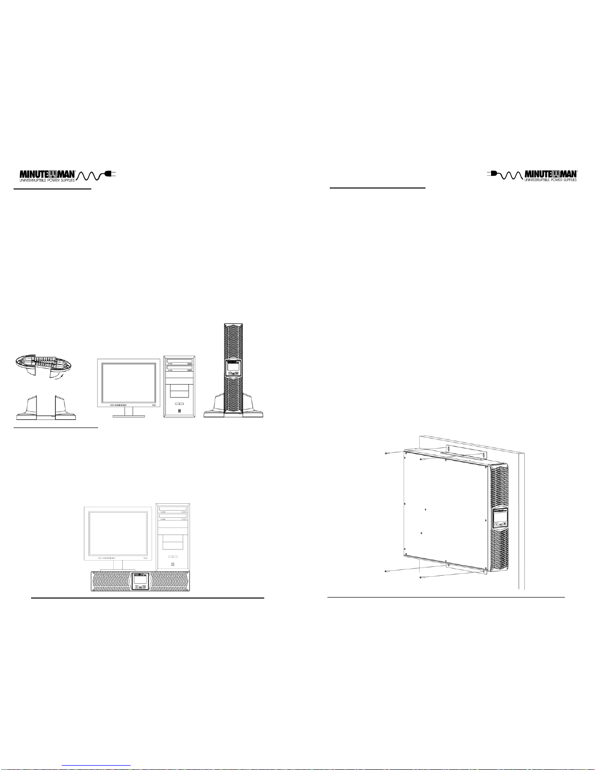
AfterremovingyourUPSfromitscarton,itshould be inspected for damage that
may have occurred in shipping. Immediately notify the carrier and place of
purchase if any damage is found. Warranty claims for damage caused by the
carrierwill not be honored. The packing materials thatyour UPS was shipped
in are carefully designed to minimize any shipping damage. In the unlikely
case that the UPS needs to be returned to the manufacturer, please use the
original packing material. Since the manufacturer is not responsible for ship-
pingdamageincurred when the system is returned, the original packingmate-
rialisinexpensiveinsurance. PLEASE SAVE THE PACKING MATERIALS!
Receiving Inspection
NOTICE: Thisequipmenthasbeentested and found to comply with the limits
for a Class B computing device in accordance with the specifications in Sub-
partJ of Part 15 of FCCRules and the Class Blimits for radio noise emissions
fromdigitalapparatussetoutintheRadioInterferenceof the Canadian Depart-
ment of Communications. These limits are designed to provide reasonable
protection against such interference in a residential installation. This equip-
mentgeneratesandusesradiofrequencyand if notinstalledandusedproperly,
that is, in strict accordance with the manufacturer's instructions, this equip-
ment may cause interference to radio and television reception. If this equip-
ment does cause interference to radio or television reception, which can be
determinedbyturningtheequipmentoffand on, the user isencouragedtotryto
correcttheinterference by one or more of thefollowingmeasures:
Re-orientthereceivingantenna.
Relocatethe computer with respect to the receiver.
Movethecomputerawayfromthereceiver.
Plugthecomputer into a different outlet sothatthe computer and receiver
areondifferentbranch circuits.
Shieldedcommunicationsinterfacecablesmustbeusedwiththisproduct.
WARNING: Changes or modifications to this unit not expressly ap-
proved by the party responsible for compliance could void the user's
authoritytooperate the equipment.
NOTE: TheseUPSsare shipped with the batteries disconnected. The batter-
ies must be connected before putting these UPSs into service. Refer to Sec-
tion 3 "Installation" for connecting the batteries.
CAUTION! This UPS series is ONLYintended to be installed in an
indoortemperaturecontrolled environment that is free ofconductive
contaminants. ThisUPSseriesisnot intended for use in a computer
room as defined in the Standard for the Protection of Electronic
Computer/DataProcessingEquipmentANSI/NFPA75.
CAUTION! The Maximum ambient operating temperature for this
UPSseries is 40°C (“0 ~ 40°C” forAmbient Operation).
ON / OFF / TEST BUTTON: Pressand release the On/Off/TestBut-
ton after one beep to turn the UPS on and supply power to the load.
The load is immediately powered while the UPS runs a five-second
selftest. Pressand release the On/Off/TestButton afteronebeepto
turntheUPSoff. TheUPSwillcontinuetochargethe batteries when-
everitispluggedintoawalloutletandthereisacceptableACvoltage
present. To perform a ten-second battery test: With the UPS in the
ACmode,pressandholdtheOn/Off/TestButtonuntilthe alarmsounds
four beeps, and then release. During the test, the UPS will switch to
the Battery mode, the On-Battery icon will illuminate and the alarm
willsound.
7
6
TheACnormal icon illuminates when the UPS is on and operating in
theACnormalmode. TheAC normal icon will extinguish when oper-
ating in the Battery mode. The AC normal icon will blink when the
UPS is operating in the Boost and/or the Buck mode.
The On-Battery icon illuminates when the UPS is operating in the
Batterymode. TheOn-Batteryiconwillextinguishwhenoperatingin
the AC normal, Boost and Buck modes.
The Weak/Bad Battery icon illuminates when the UPS detects a
weakbattery,badbatteryorifthebattery is disconnected. The Weak/
BadBatteryiconisextinguishedwhenthe battery's condition isgood.
The Fault icon illuminates when the UPS detects an internal fault.
The Fault icon is extinguished when the UPS is operating properly.
The Site Wiring icon illuminates when the UPS detects a site wiring
problem. The SWF icon is extinguished when the UPS is con-
nectedto proper site wiring.
TheLoadLevelBarGraphoperatesasfollows:
LED #1: When the attached load is >20% the LED will illuminate.
LED #2: When the attached load is >40% the LED will illuminate.
LED #3: When the attached load is >60% the LED will illuminate.
LED #4: When the attached load is >80% the LED will illuminate.
LED #5: When the attached load is >100% the LED will illuminate.
When the amount of load attached to the UPS exceeds 110% of its
powerrating;theOverloadiconwillflash Off and On, all of the LEDs
in the Load Level Bar Graph will be illuminated and the UPS will
sound a constant alarm to indicate that there is an Overload condi-
tion.
TheBattery Capacity Bar Graph operates as follows:
LED #1: When the battery capacity is >20% the LED will illuminate.
LED #2: When the battery capacity is >40% the LED will illuminate.
LED #3: When the battery capacity is >60% the LED will illuminate.
LED #4: When the battery capacity is >80% the LED will illuminate.
LED #5: When the battery capacity is >100% the LED will illumi-
nate.
TheMulti-FunctionOn/Off/Test Button functions as follows:
WhentheUPSisOff,pressandreleasetheOn/Off/Testbuttonafter
one beep to turn the UPS On.
WhentheUPSisOn,pressandreleasetheOn/Off/TestButtonafter
one beep to turn the UPS Off.
When the UPS is in the Normal AC mode, press and hold the On/
Off/Testbuttonforfourbeeps,thenreleasethebutton. TheUPSwill
performa10-secondSelfTest.
When the unit is operating in Battery mode, pressing theAlarm Si-
lencerButtonwillsilence the audible alarm. Once the UPS reaches
the LBW (Low Battery Warning) threshold the alarm will be re-acti-
vated. The alarm cannot be silenced during the LBW alarm. Once
the UPS transfers to theAC mode the alarm will be reset to default.
The Scroll Button allows the user to scroll through the UPS param-
etersthatare available on the LCD screen.
CONTROL PANEL
NOTE: TheLCDbacklightwill illuminate for1-minutewhentheUPS switches tothe
Battery mode. When the UPS has an event and/or an error code the LCD backlight
will turn on and remain on to alert the user that an event has occurred.
9
8
INSTALLATION PLACEMENT
This UPS series is ONLYintended to be installed in an indoor temperature
controlledenvironmentthatisfreeofconductivecontaminants. DONOToper-
ate the UPS in: extremely dusty and/or unclean areas, locations near heating
devices, water or excessive humidity, or where the UPS is exposed to direct
sunlight. Selectalocation,whichwillprovidegoodaircirculationfortheUPSat
all times.
Route power cords so they cannot be walked on or damaged. This
UPS series is not intended for use in a computer room as defined in the
Standard for the Protection of Electronic Computer/Data Processing Equip-
mentANSI/NFPA75. Typical battery life is 3 to 5years. Environmentalfactors
do affect battery life. High temperatures, poor utility power, and frequent,
short duration discharges have a negative impact on battery life.
OperatingTemperature(Maximum): 0to40degrees C (+32to+104degreesF)
OperatingElevation: 0 to 3,000m (0 to +10,000 ft)
OperatingandStorage Relative Humidity: 95%, non-condensing
StorageTemperature: -15 to +45 degrees C(+5 to +113 degrees F)
Storage Elevation: 0 to 15,000m (0 to +50,000 ft)
REAR PANEL
1. The RS232 Communications Port is for UPS monitoring and control.
2. The USB Communications Port is for UPS monitoring and control. (See
Note on page 17).
3. The RJ11 REPO (Remote Emergency Power Off) Port is for UPS control.
This connection is not for Telecommunication use.
4. The option slot is for option cards.
5. TheBatteryBackupoutputreceptacles. The output receptacles are electri-
cally wired into two segments to support the "Load Shedding Function"
(Labeled Load 1 & Load 2). The locking andAlways On receptacles (La-
beled Load 3) do not support the "Load Shedding Function". NOTE: The
locking recptacle is not on all models.
6. The input circuit breaker will trip in the event the load exceeds the UPS’s
power rating.
7. The input power cord.
8. The dipswitch is for setting the Inverter (On-Battery) output voltage.
9. The External Ground Stud is for connecting an external ground wire.
10. The R-J11/R-J45 modular connectors are used for 10/100 Base-T Net-
work/single line Phone/Fax/Modem protection.
Output Power Receptacles
E750RT2U NEMA5-15P
Model#
E1500RT2U
E2000RT2U
E1000RT2U
E3000RT2U
NEMA5-15P
NEMA5-15P
NEMA5-20P
NEMAL5-30P
6-NEMA5-15R (Controllable)
2-NEMA 5-15R (Always On)
6-NEMA5-15R (Controllable)
2-NEMA 5-15R (Always On)
6-NEMA5-15R (Controllable)
2-NEMA 5-15R (Always On)
8-NEMA5-15/20R (Controllable)
1-NEMA L5-20R (Always On)
7-NEMA5-15/20R (Controllable)
1-NEMA L5-30R (Always On)
INSTALLATION
Besuretoread the installation placement and all the cautions beforeinstalling
the UPS. Place the UPS in the final desired location and complete the rest of
theinstallationprocedure. TheseUPSs are shipped with the internal batteries
disconnected. The batteries must be connected before putting these UPSs
into service. See the "Connecting the Batteries" procedure to connect the
batteries and see the "Rackmount Configuration" to install the UPS into the
rack. USE CAUTION: The UPS is heavy. Use the appropriate number of
personnelwheninstalling the UPS.
Input Power Plug
(All power cords are 10ft)
CAUTION! DO NOT USE THE MOUNTING BRACKETS TO
LIFT THE UPS. The mounting brackets are ONLYfor securing the
UPS to the rack.
11
10
CONNECTING THE BATTERIES
(QUALIFIEDSERVICEPERSONNELONLY)
Please read all of the WARNINGS and CAUTIONS before attempting to con-
nectthe batteries.
1. Remove the front panel retaining screws.
2. Lay the front panel on top of the UPS.
3. Verify proper polarity. Connect the battery connectors (red and black)
together.
NOTE: Some sparking may occur this is normal.
4. Re-install the front panel onto the UPS.
5. Re-install the front panel retaining screws.
6. Connecting the Batteries is complete. See Connecting your Equipment.
RACKMOUNT CONFIGURATION
This UPS comes with mounting brackets for the standard 19" (46.5cm) rack
installed on the UPS. The mounting brackets to fit a 23" (59.2cm) rack and
Rail Kits for 4-post racks and cabinets are also available. The screws for
mounting the UPS to the rack are included.
CAUTION! DO NOT USE THE MOUNTING BRACKETS TO
LIFT THE UPS. The mounting brackets are ONLYfor securing the
UPS to the rack.
NOTE: The mounting brackets can be mounted in the middle of the UPS.
1. Remove the UPS from the shipping box.
2. Mountthe UPS into the rack andsecure with the retaining screws. WARN-
ING: Use two or more people when installing the UPS. Use CAUTION, the
UPS is extremely heavy. Do not move the rack after the units have been in-
stalled. The rack may become unstable due to the weight distribution.
3. The Rackmount Configuration is complete. See Connecting the Batteries.
13
12
WALLMOUNTCONFIGURATION
The wallmount configuration allows the user to mount the UPS on the wall. There is
a wallmount bracket kit available for the UPS. The kit includes two wall mounting
brackets, ten retaining screws, and the wallmount template. WARNING: Use two or
more people when installing the UPS. Use CAUTION, the UPS is extremely heavy.
The UPS's side panels have mounting bracket screw holes for attaching the wall
mounting brackets.
1. Once the location and position of the UPS has been determined, lay the UPS do-
wn flat.
WARNING: The UPS must be installed in the proper up-right position. If the UPS is
not installed in the proper up-right position the Batteries will be damaged. Once the
UPS is placed on the wall, looking at the front panel the YELLOW Battery discon-
nected label on the top cover of the UPS MUST be on your left hand side.
2. Align the mounting brackets with the mounting bracket screw holes and attach w-
ith the six retaining screws.
3. Use the template to mark the screw hole position on the wall. CAUTION, you sh-
ould always were protective gear for your hands and eyes when operating power
tools.
4. Attach the four retaining screws to the wall and make sure that all of the retaining
screws are screwed into structural material. Then clean the area of any loose m-
aterial. Do not tighten the retaining screws all the way, leave approximately 3/8" of
the retaining screws sticking out.
5. Position the UPS, so that the mounting bracket keyed holes line up with the four
retaining screws. Slide the UPS down until its resting securely on the four retai-
ning screws.
6. Tighten the four retaining screws to secure the UPS to the wall.
7. The LCD panel can be rotated to read in the up-right position. Remove the front
panel from the UPS. On the backside of the front panel, push the LCD panel out-
wards, the panel will pop out. Position the LCD panel so that it reads in the up-
right position. Re-install the front panel on the UPS.
8. The Wallmount Configuration is complete. See Connecting your Equipment.
TOWERCONFIGURATION
The tower configuration allows the user to install the UPS in the up-right position
next to a tower computer. The tower brackets are provided with the UPS. WARNING:
Use two or more people when installing the UPS. Use CAUTION, the UPS is ex-
tremelyheavy.
1. Once the location of the UPS has been determined, place the tower brackets in
the desired location.
WARNING: The UPS must be installed in the proper up-right position. If the UPS is
not installed in the proper up-right position the Batteries will be damaged. Once the
UPS is placed in the tower brackets, looking at the front panel the YELLOW Battery
disconnected label on the top cover of the UPS MUST be on your left hand side.
2. Slide the UPS into the tower brackets. Make sure that the UPS is stable.
3. The LCD panel can be rotated to read in the up-right position. Remove the front
panel from the UPS. On the backside of the front panel, push the LCD panel out-
wards, the panel will pop out. Position the LCD panel so that it reads in the up-
right position. Re-install the front panel on the UPS.
4. The Tower Configuration is complete. See Connecting your Equipment.
DESKTOPCONFIGURATION
The desktop configuration allows the user to install the monitor, the computer and
the UPS in one single stack. WARNING: Use two or more people when installing the
UPS. Use CAUTION, the UPS is extremely heavy.
1. Once the location of the UPS has been determined, lay the UPS down flat on the
desk.
2. Stack the computer and then the monitor on top of the UPS. NOTE: Do not stack
the UPS on top of the computer. The UPS is heavy and may damage the other
equipment.
3. The Desktop Configuration is complete. See Connecting your Equipment.
15
14
SYSTEM OVERVIEW
This Line-Interactive UPS protects computers, internetworking, and telecom-
municationsequipmentfromblackouts, brownouts, overvoltages, and surges.
TheAVR function continuously corrects the voltages,in-betweenthebrownout
and overvoltage transfer points (80 - 164VAC), to a safe usable level. When
the UPS is operating in theAVR mode the audible alarm will remain silent and
theACNormaliconwillflash. DuringnormalACoperation,theUPSwillquietly
and confidently protect your system from power anomalies.
CHARGING THE BATTERY
The UPS will charge the internal batteries whenever the UPS is connected to
an AC source and there is an acceptable AC voltage present. It is recom-
mended that the UPS's batteries be charged for a minimum of 4 hours before
use. The UPS may be used immediately, however, the “On-Battery” runtime
may be less than normally expected. NOTE: If the UPS is going to be out of
service or stored for a prolonged period of time, the batteries must be re-
charged for at least twenty-four hours every ninety days.
CHECKING THE SITE WIRING FAULT
After plugging the UPS into the AC wall outlet, check the Site Wiring Fault
(SWF) icon on the front panel of the UPS. If the SWF icon is illuminated, the
UPSis plugged into an improperly wiredAC wall outlet. Ifthe UPS indicates a
Site Wiring Fault (SWF), have a Qualified Electrician correct the problem.
COMMUNICATIONS PORT CONNECTION (OPTIONAL)
The Power Monitoring Software and interface cables can be used with the
UPS. Use only the interface cables that come with these UPSs. Connect the
interface cable (Serial or USB) to the appropriate communications port on the
rear panel of the UPS. Connect the other end of the cable to the device that
will be monitoring/controlling the UPS. NOTE: Connecting to the Communi-
cations Port is optional. The UPS works properly without this connection.
(For USB port see Note on page 17).
CONNECTING THE UPS TO AN AC SOURCE
PlugtheUPSintoatwo pole, three wire, groundedAC wall outlet. TheACwall
outlet shall be near the UPS and shall be easily accessible. The plug on the
input power cord on this UPS series is intended to serve as a disconnect
device. Do not use extension cords, adapter plugs, or surge strips.
NETWORK/PHONE/FAX/MODEM PROTECTION CONNECTION (OP-
TIONAL)
Connecta10/100Base-Tnetwork,singlelinephone,FaxorModemlinetothe
RJ11/45 modular connectors on the rear panel of the UPS. This connection
will require another length of telephone or network cable. The cable coming
fromthetelephoneservice or networkedsystemisconnectedtothe portmarked
“IN”. The equipment to be protected is connected to the port marked "OUT".
NOTE: ConnectingtotheNetwork/Phone/Fax/Modem modular connectors is
optional. The UPS works properly without this connection.
CONNECTING YOUR EQUIPMENT
Plug the equipment into the output receptacles on the rear panel of the UPS.
Do not use extension cords, adapter plugs or surge strips on the output of the
UPS. Ensure that you do not exceed the maximum output rating of the UPS
(refer to the information label or the Electrical Specifications in this manual).
CAUTION! DO NOT connect a laser printer to the output receptacles on
the UPS, unless the UPS is rated 2000VA or greater. A laser
printer draws significantly more power when printing than at
idle and may overload the UPS. RJ11 REPO (Remote Emergency Power Off) PORT (OPTIONAL)
Connect one end of the RJ11 cable to the REPO port and the other end of the
RJ11 cable to the EPO switch. In the AC or the Battery mode short pin4 to
pin5 for approximately 0.5-seconds to shutdown the UPS. The UPS must be
turned off and then back on again to restart the UPS. NOTE: Connecting to
the REPO port is optional. The UPS works properly without this connection.
This connection is not for Telecommunication use.
Block Diagram of the Basic Wiring and Internal Circuit Configuration
17
16
TheUPSwill charge the batteries with the UPS intheon or off position as long
astheUPSispluggedintothewalloutletandthere is an acceptableAC voltage
present (80 - 164VAC). When a blackout, brownout, or an overvoltage condi-
tion occurs; the UPS will transfer to the battery mode, the On-Battery icon will
illuminateand the audible alarmwill sound once everyten-seconds indicating
that the commercial power is lost or unacceptable. When the commercial
power returns or is at an acceptable level, the UPS will automatically transfer
back to the AC normal mode and start recharging the batteries. During an
extended outage when there is approximately two-minutes of backup time re-
maining the audible alarm will sound twice every five-seconds. This Low Bat-
tery Warning is letting the user know that they should save all open files and
turn off their computer. When the batteries reach the predetermined level the
UPS will automatically shutdown protecting the batteries from over discharg-
ing. Once the commercial power returns the UPS will automatically restart,
providingsafe usable power to the connected equipmentand start recharging
thebatteries.
TURNING THE UNIT ON/OFF
On / Off / Test Button
Press and release the On/Off/Test Button after one beep to turn the UPS on
andsupplypowertotheload. Theloadisimmediatelypoweredwhilethe UPS
runs a five-second self test. Press and release the On/Off/Test Button after
one beep to turn the UPS off. The UPS will continue to charge the batteries
whenever it is plugged into a wall outlet and there is acceptable AC voltage
present.
SELF TEST
Theselftestfeature is useful to verify the correct operation of theUPSandthe
condition of the batteries. With the UPS in the AC normal mode, press and
hold the On/Off/Test Button for four beeps, then release the button. The UPS
will perform a ten-second self test. During the self test, the UPS will switch to
thebatterymode and the On-Battery icon will illuminateandthe audible alarm
will sound. The length of the test that is automatically performed every two
weeks is longer than the start-up or user invoked test. This test will run for
approximately fifteen-seconds to measure the battery’s capability to provide
an acceptable amount of runtime. If the UPS fails a self test, one of the icons
will remain illuminated indicating the type of problem. NOTE: The UPS will
automatically perform a self test on start-up and every two weeks.
COMMUNICATIONS PORTS (RS232 and USB)
The RS232 communication port is a standard DB9 female with both RS232
and simulated contact closure capability. The UPS will poll the port and acti-
vate the port for RS232 or contact closure in accordance with the type of
cable it finds connected to the port. To change the port configuration requires
the unit be turned off and restarted with the desired cable connected. The
pinout for the port is depicted per the chart below:
Pin 1: Simulated contact closure Low Battery Warning, NO
Pin 2: /TXD
Pin 3: /RXD and receive UPS shutdown command (connect to pin 9 for 4-
seconds. The shutdown command is only active in the battery mode)
Pin 4: Not Used
Pin 5: Ground
Pin 6: Not Used
Pin 7: Not Used
Pin 8: Simulated contact closureAC fail, NO
Pin 9:Atx Signal (high level: +12V +/-2V, low level: -15V +/- -2V)
DIPSWITCH SETTINGS
The dipswitch setting may be changed by the user to set the desired Inverter
(On-Battery)outputvoltage. The dipswitch must be set to the desired Inverter
(On-Battery)outputvoltageandthentheUPSmustbeturnedoffandrestarted
to reconfigure the microprocessor and save the changes. The Inverter (On-
Battery)outputvoltagesettingcanbeeither 120VAC defaultor125VAC. Chang-
ing the Inverter (On-Battery) output voltage to 125VAC, will also change the
Bucksetpoint.
LOAD SHEDDING FUNCTION
Theoutput receptacles are electrically wiredinto two segments to support the
"Load Shedding Function" (Labeled Load 1 & Load 2). The user can control
the two segments individually or both at the same time. The Load Shedding
Function is controllable by the Power Monitoring Software or the SNMP card.
NOTE: Theoutputsegmentlabeled Load 3 does not support the "LoadShed-
ding Function".
POWER MONITORING SOFTWARE
The UPS comes with a Power Monitoring Software CD. See the software CD
for the installation of the Power Monitoring Software.
USB PORT
TheUSBprotocolis HID. The HID USB driver is standard in the WindowsOS.
Simply plug the USB cable into the UPS and the computer then follow the
prompts on the screen. NOTE: When using the UPS's USB port with
Windows XP, 7 or 8 the Power Options in the Control Panel may need to
be configured.