Paradigm DCOR2SC User manual

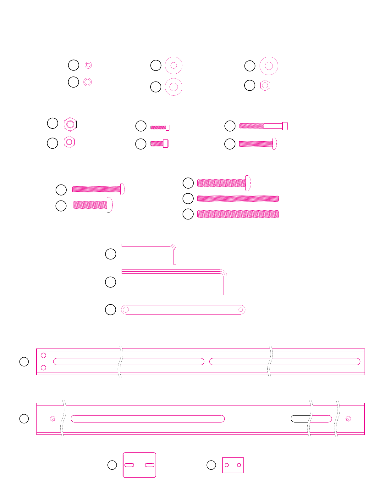
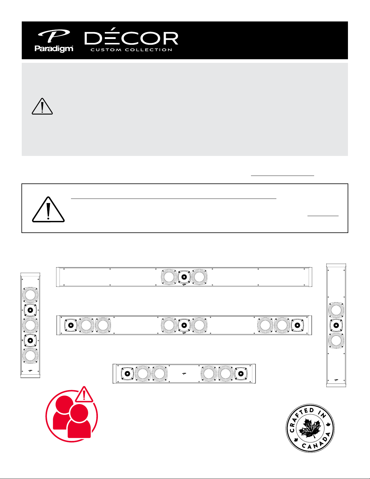
Instructions for Décor
TV Mounting Bracket
Wall mount your speakers securely
enough that they cannot fall and cause
personal injury or damage to property.
NON LIABILITY: We are aware that the mounting
assemblies provided for speakers in this manual could be
used for purposes and in ways other than those for which
they were intended. The manufacturer, distributor, retailer
and their respective agents cannot be held responsible
or liable for injuries or property damage—direct, indirect
or consequential—arising from the use of or inability to
use these products safely and properly. Every effort has
been made to provide accurate, error-free installation
instructions. Paradigm Electronics Inc. disclaims liability
for difficulties that may arise from the misinterpretation
of information contained in these instructions.
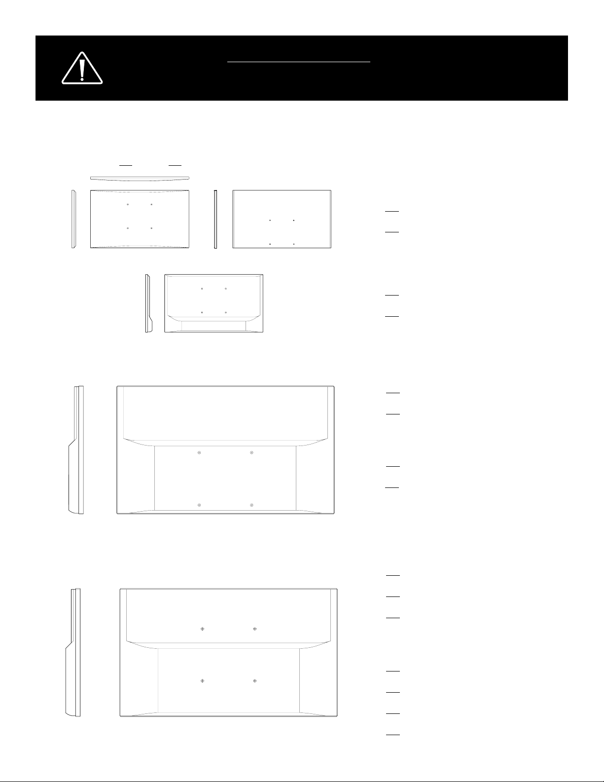
An Important Note About TV Mounting Bracket:
Ensure the TV mounting bracket, attached to the wall, will accommodate
the extra weight of the Décor speakers and Décor Mounting Rails BEFORE
attaching to wall. If unsure, consult dealer or TV mount manufacturer.
2SC 1C
1SC
1S
2S
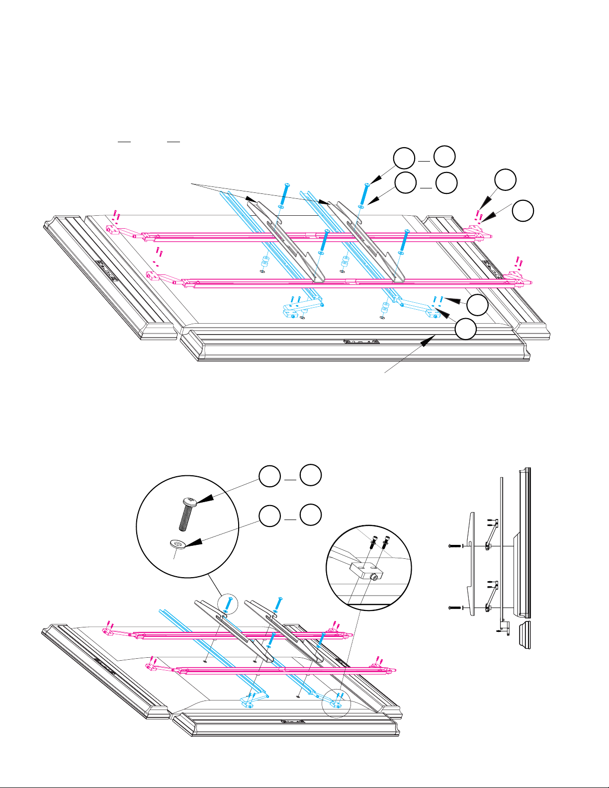
HORIZONTAL AND VERTICAL - 55” to 88”
CAUTION: 2 PERSON
INSTALLATION

(2) SPEAKER
BRACKETS
(2) RAIL
BRACKETS
(2) VERTICAL RAILS
BB
AA
Z
(1) 7/64” HEX
ALLEN KEY
(1) 5/32” HEX
ALLEN KEY
(2) HINGES
W
X
Y
(4) #12-24 x 1-3/4”
SCREWS
K
(4) M6-30mm
SCREWS
L
(4) #6-32 x 5/8”
SCREWS
(4) #12-24 x 1/2”
SCREWS
I
J
(4) M6-50mm
SCREWS
N
(4) M6-70mm
SCREWS
O
(4) M8-30mm
SCREWS
P
(4) M8-50mm
SCREWS
R
(4) M8-70mm
SCREWS
S
(2) M6-85mm
THREADED RODS
(2) M8-85mm
THREADED RODS
U
V
(4) SMALL
SPLIT WASHERS
A
(4) SPLIT
WASHERS
B
(8) SPACERS
E
(6) M6-NUTS
F
(6) M8-NUTS
G
(8) LARGE
M6-WASHERS
C
(8) LARGE
M8-WASHERS
D
RAIL ASSEMBLIES
HARDWARE INCLUDED (KIT0078 or KIT0079)
Depending on TV type, not all hardware listed will be required.

(4) SPEAKER
BRACKETS
(4) RAIL
BRACKETS
(4) SLIDING
RAILS
(2) FIXED
RAILS
CC
AA
Z
DD
(1) 7/64” HEX
ALLEN KEY
(1) 5/32” HEX
ALLEN KEY
(4) HINGES
W
X
Y
(8) SMALL
SPLIT WASHERS
(8) LARGE
M6 WASHERS (8) SPACERS
(6) M6-NUTS
(8) LARGE
M8 WASHERS
(8) SPLIT
WASHERS
A
B
C
D
E
F
(6) M8-NUTS
(4) 1/4”-20 NUTS
(8) #6-32 x 5/8”
SCREWS
(8) #12-24 x 1/2”
SCREWS
(8) #12-24 x 1-3/4”
SCREWS
(4) M6-35mm
SCREWS
K
M
I
J
G
H
(4) M8-50mm
SCREWS
(2) M6-85mm
THREADED RODS
(2) M8-85mm
THREADED RODS
R
U
V
(4) M8-35mm
SCREWS
(4) M6-50mm
SCREWS
N
Q
RAIL ASSEMBLIES
HARDWARE INCLUDED (KIT0081 or KIT0082)
Depending on TV type, not all hardware listed will be required.

CAUTION: THIS IS A TWO PERSON PROCEDURE. TWO PEOPLE ARE NEEDED TO
CARRY OUT THE INSTRUCTIONS OUTLINED BELOW. BE CAREFUL NOT TO DAMAGE
TV AND SPEAKER DRIVERS DURING BRACKET INSTALLATION.
Before installing, identify TV profile type (A, B or C) and gather the necessary
mounting hardware required from the contents provided.
VERTICAL:
(4) M6-50mm Screws (N)
OR (4) M8-50mm Screws (R)
(4) M6-Washers (C)
OR (4) M8-Washers (D)
(8) Spacers (E)
(2) Railing Assemblies (see step 1)
VERTICAL:
(4) M6-50mm Screws (N)
OR (4) M8-50mm Screws (R)
(4) M6-Washers (C)
OR (4) M8-Washers (D)
(8) Spacers (E)
(2) Railing Assemblies (see step 1)
VERTICAL:
(2) Threaded Rods M6-85mm (U)
OR (2) Threaded Rods M8-85 (V)
(2) M6-35mm Screws (M)
OR (2) M8-35mm Screws (Q)
(8) M6-Washers (C)
OR (8) M8-Washers (D)
(6) M6-Nuts (F)
OR (6) M8-Nuts (G)
(2) Rail Assemblies (see step 1)
(B) PROFILE TV (4 screw holes at base of TV)
(C) PROFILE TV (2 screw holes TOP and BOTTOM)
(A) CURVED or SLIM or PROFILE TV (4 screw holes at TOP of TV)
HORIZONTAL:
(4) M6-50mm Screws (N)
OR (4) M8-50mm Screws (R)
(4) M6 Washers (C)
OR (4) M8 Washers (D)
(8) Spacers (E)
(2) Railing Assemblies (see step 1)
HORIZONTAL:
4) M6-30mm Screws (L)
OR (4) M8-30mm Screws (P)
(4) M6-Washers (C)
OR (4) M8 Washers (D)
(2) Rail Assemblies (see step 1)
HORIZONTAL:
(2) M6-30mm Screws (L)
OR (2) M8-30mm Screws (P)
(8) M6-Washers (C)
OR (8) M8-Washers (D)
(6) M6-Nuts (F)
OR (6) M8-Nuts (G)
(2) Rail Assemblies (see step 1)

MOUNTING PROCEDURE
K
J
B
YZ
CC
DD
C
AA
B
K
J
Z
C
H
Y
AA
CC
DD
A
K
B
Z
Y
J
AA
BB
J
B
Y
Z
AA
BB
K
Horizontal speaker mounting rails, with hinges, have been preassembled. Image below
shows preassembled parts and hardware, in exploded view.
Vertical speaker mounting rails, with hinges, have been preassembled. Image below
shows preassembled parts and hardware, in exploded view.

3. Position the assembled VERTICAL speaker rail assemblies on top of the HORIZONTAL
speaker rails. Align the rails so holes match up.
1. Lay TV facedown, on floor. Position Décor SPEAKERS WITH GRILLES ON along side
and bottom edges of TV. Be careful not to damage the screen or the speaker drivers.
Be sure to position speaker with terminals away from TV.
NOTE: Be sure to move speaker and grille together when positioning against TV.
2. Position the assembled HORIZONTAL speaker rail assemblies on back of TV. Lineup
rail slots over TV mounting holes. Spacers may be needed (E) to increase distance
from TV under rails if TV has lower profile than speakers. Ensure center of Décor Fixed
Mounting Rail is centered to width of TV.
E
If TV or TV
protrusion is
thinner than speaker,
spacers or washers
are required under
Décor mounting rails.

4. Position TV rails/brackets that are included in TV Wall Mount (purchased separately)
and place over top of all rail assemblies as illustrated.
(A) CURVED or SLIM or PROFILE TV (4 screw holes at TOP of TV)
O
CI
C
O
I
A
TV Mounting
Brackets
(Purchased Separately)
R
S
D
D
OR
OR
OR
OR
N
C
(B) PROFILE TV (4 screw holes at base of TV)
Channel in speaker
back used to drive
bracket screws
I
A

R
G
D
D
OR
OR
OR
OR
OR
F
U
C
C
WASHER ON PART “U” OR “V”
TO BE SET ON SAME LEVEL
WITH TV REAR PROTRUSION
(C) PROFILE TV (2 screw holes TOP and BOTTOM)
5. Secure Décor Speaker rails and TV mounts, as shown, using washers and screws.
DO NOT TIGHTEN SCREWS AT THIS STAGE.
6. Attach speaker brackets (Z) to speaker using washers (A) and screws (I).
Channel in speaker
back used to drive
bracket screws
A
I
Z
V
N

7. Ensure speakers are properly aligned with TV before tightening all screws
and threaded rods with nuts (F) or (G) if applicable, only when using threaded
rods (U) or (V). Now, tighten screws securely.
At this stage, mounting system is now ready to be installed on wall.
Follow instructions which came with your TV mount to place TV on wall.
CAUTION: CAREFULLY LIFT BY RAILS. DO NOT LIFT BY TV EDGE. Support
entire bracket assembly and place onto TV Mount on wall (purchased
separately). Follow TV Mounting instructions. WHEN RE-HANGING TV,
SUPPORT BOTH THE TV AND THE ATTACHED SPEAKERS.
Fine Adjustments:
After hanging TV, according to manufactures bracket instructions, adjust speaker if
needed to be flush with TV. Use Allen Key to secure tightly.

NOTES

NOTES

MAN0167 REV1
To ensure proper installation and enjoy all of the exceptional sound these speakers
are designed to provide, please read this manual and follow all instructions.
Paradigm Electronics Inc., 205 Annagem Blvd., Mississauga, ON L5T 2V1
T: +1 905.564.1994
Other manuals for DCOR2SC
1
This manual suits for next models
4
Table of contents
Other Paradigm TV Mount manuals