Paradox Hellas S.A. Elix User manual

Elix - User Guide
1. General Description
Indoor Emergency Lighting ELIX has a double function. It can operate as:
1) Emergency Lighting, where it is activated on mains power loss (when voltage drops below acceptable
limit).
2) Continuous Operation Lighting with two (2) levels of brightness:
• Brightness Level 1: Mains power is present
• Brightness Level 2: Mains power is lost
ELIX also provides:
• A PRG/TEST button, for testing and programming
• Three (3) LED indications: FLT=Fault (yellow LED), PWR=Power (green LED) and BAT=Battery Fault
(red LED)
• Up to 2.5 hours of emergency lighting duration (at maximum brightness)
2. TEST button operation
Figure 1. ELIX LED indications
If the PRG/TEST button is pressed for an interval:
• Less than 3 seconds, the system’s diagnostic test starts.
• Between 3 and 30 seconds, the system’s programming operation starts.
• More than 30 seconds, the system restores the default settings.
2.1 Test Procedure
1) Battery Internal Resistance Test
- The battery presence is checked.
- The battery internal resistance is checked.
- The battery degree of charge is checked.
2) LED Lights Test
- A cycle through all 5 light intensities is done
- If there is an open-circuit or a short-circuit fault with the LED operation, an error is indicated.
2.2 System Programming
To enter the system programming the user presses the PRG/TEST button for more than 3 seconds and until
the PWR LED starts blinking. The PWR LED will remain in this blinking state until the programming ends.

The system will automatically exit the programming mode if no user interaction takes place for more than 60
seconds.
The programming procedure consists of two (2) steps. The user advances to the next step by pressing the
PRG/TEST button for more than 3 seconds. The steps are described below:
STEP 1: Brightness level with main power present (PWR and FLT LEDs blinking)
In this step the user sets the brightness level produced by ELIX while the mains supply power is present. By
instantaneously pressing the PRG/TEST button the brightness cycles through the six (6) available levels
(including the o state). When the desired brightness is active, the user presses the PRG/TEST button for
more than three (3) seconds; the brightness level is saved and the programming continuous to STEP 2.
If EMERGENCY ONLY operation is required the user must select Zero Brightness (Lighting
element OFF).
STEP 2: Brightness level during mains power loss (PWR and BAT LEDs blinking)
In this step the user sets the brightness level produced by ELIX while the mains supply power is lost. By
instantaneously pressing the PRG/TEST button the brightness cycles through the ve (5) available levels
(minimum to maximum brightness). When the desired brightness is active, the user presses the PRG/TEST
button for more than three (3) seconds; the brightness level is saved and the programming is completed.
After the completion of the programming steps ELIX returns to normal operation.
During the programming operation, ELIX does not check the mains power or execute any
diagnostic tests.
3. Indications Functionality
PWR Indication (green LED)
• OFF: Mains voltage is low or lost.
• ON: Mains voltage is present.
FLT Indication (yellow LED)
• OFF: Light Elements in normal mode.
• Blinking: Light Elements Fault.
BAT Indication (red LED)
• OFF: Battery is working properly.
• ON: Battery Fault.
• Blinking: Battery has lost capacity and will need to be replaced soon.
SYSTEM IN NORMAL OPERATION MODE
LED INDICATOR STATE Description
PWR (green) ON Mains power present
OFF Mains power is lost
FLT (yellow) BLINK Light element Fault
BAT (red) ON Battery Fault
BLINK Battery reduced capacity, needs to be replaced soon
SYSTEM IN PROGRAMMING MODE
LED INDICATOR STATE Description
PWR BLINK System enters programming mode
FLT BLINK System is in STEP 1
BAT BLINK System is in STEP 2

4. Technical Characteristics
Power Supply 230VAC / 50Hz
Max. Power Consumption Less than 5VA
Light Source 12 LED
Battery 3.6V 1.0Ah NiCd
Emergency Operation Time From 150min to 240min depending on luminance setting
Luminance setting 5 steps (20, 40, 60, 80 & 100%)
Light source intensity (230V) 100lm
Switch over Voltage Between 150 ~ 190V
IP rating IP20
Isolation Category Mains connection Doubly isolated
Environmental Temperature: 5 to 45 °C
Humidity: 5 to 95% RH, non-condensating
Dimensions [WxHxD] 260x125x35.5 mm
Indication Area Dimensions [WxH] 228x75 mm
Guarantee 3 years (1 year for the battery)
5. Installation instructions
ATTENTION! The installation and maintenance of this unit must be performed by qualied
personnel only. Mains voltages are lethal. Electrical wiring must be compliant to all safety and
electrical regulations that apply.
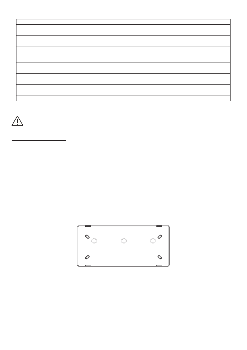
Wall mounting installation:
The unit should be surface mounted. To wall mount the cabinet:
1. Remove the two screws on the left and right side of the device to be installed.
2. Open the case by pushing down on the two plastic tabs and pulling the face of the device forward.
3. Remove the reector assembly by gently holding it from it’s bottom side and pulling outward.
4. Use the back cover to mark the required drill points on the mounting surface (wall). Drill the required
holes.
5. Remove one of the three available knock outs, pass the mains cable through.
6. Place the back cover on the wall and x it in place with screws.
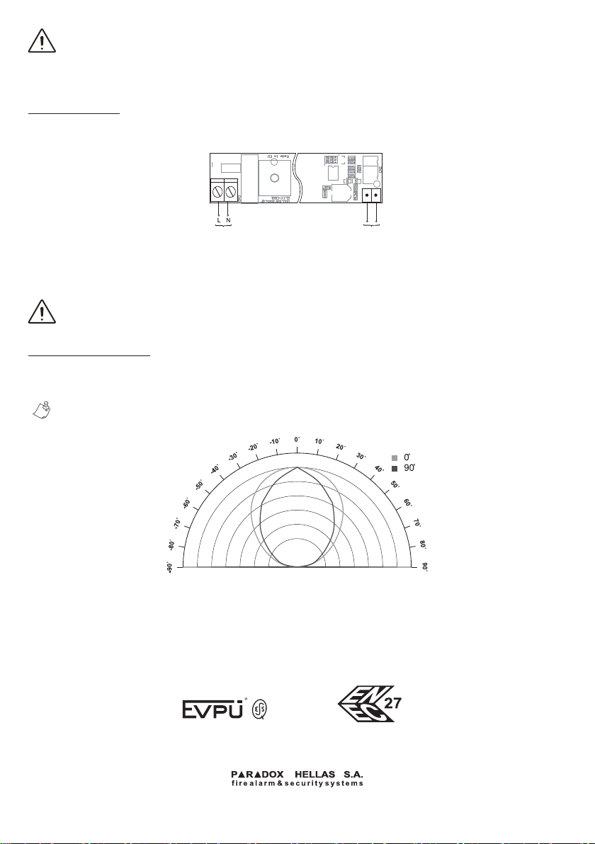
7. Connect the mains cable on the terminal block.
8. Place the reector assembly by sliding it in place.
9. Connect the battery (see battery replacement)
10. Place the front cover by hooking the two hinges at the bottom of the unit and gently pushing upward.
Push on the top side until the plastic tabs lock in place.
11. Place the screws in place paying attention to not overtight them.
Figure 2. ELIX wall mounting base
Battery replacement:
ELIX contains a replaceable battery. The unit contains electronics required for the verication of the battery’s
good health. Change the battery when the indication BAT blinks. Change the battery according to the
following procedure:
1. Disconnect the 220VAC power from ELIX.
2. Remove the screws holding the battery cover in place, then remove the battery cover.
3. Remove the old battery from the battery holder.
4. Gently pull the battery cable until the battery connector is visible.
5. Disconnect the old battery from the exposed connector.
6. Connect the new battery observing the correct polarity.

ATTENTION: After installation, proper operation is established after the batteries have been
charged for 24 hours.
The battery connectors employ plastic guides ensuring the correct connection of a new battery.
Do not use excessive force to connect the battery as this is an indication of improper alignment.
Reverse connection of the battery will cause permanent damage to the Luminary.
Mains connection:
Use the terminal block to connect the AC power cable to the panel. Ensure that the power cable is safe to
handle (has no power). See gure below.
Mains Power Supply
230 VAC / 50-60Hz
Battery
3.6V 1.0Ah NiCd
Figure 3. ELIX mains & battery connection
The diameter of the wires must be between 0.823 and 3.31 mm2 (12-18 AWG).
If multi stranded wire is used for the mains connection, the ends of the wire should never be
tinned. If desired, wire ferrules may be tted.
Controlgear is suitable only for ELIX LDM.
Lighting Element Failure
The lighting elements of the ELIX unit are NOT user replaceable. In case of failure the unit must be either
replaced or serviced by qualied personnel. This failure is indicated by the RED blinking fault light.
This device contains no user replaceable parts inside.
* Persisting Faults require the replacement of the unit.
Figure 4. ELIX angular light distribution
EMERGENCY LIGHTING LABELING EXPLANATION:
X: Self contained
1: Maintained
A: Including test device
150: 2.5 hour duration
Elix User Guide / ELX-UGE ver.1.0, rev.9, ΜΑΥ 2020
CE Certied by:
00114/101/1/2017
008/ENEC/2017
EN60598 | EN62031 | EN62471 |
EN61347 | EN55015 | EN61547
www.paradox.gr
Korinthou 3, Metamorfosi 144 51, Athens-Greece
Table of contents
Popular Lighting Equipment manuals by other brands

Fineart
Fineart FINE 2000BEAM manual

Astral Pool
Astral Pool SKIMMER Installation and maintenance manual

FOS Technologies
FOS Technologies FOS GLOW II user manual

C.P. Electronics
C.P. Electronics EBR-4SC Product guide

Night Stick
Night Stick NSR-2124 instruction manual

REV
REV BY-XYD534 Assembly and operating instructions