Paragon GUARDIAN Manual

OPERATION & MAINTENANCE MANUAL
GUARDIAN
SPACE PRESSURE MONITOR
WITH REMOTE AUXILLARY ALARM
PARAGON CONTROLS INCORPORATED
P.O. BOX 99
FORESTVILLE, CALIFORNIA 95436-0099
(707) 579-1424
/SPM
REV. 7, 7/24/09

TABLE OF CONTENTS
SECTION PAGE
1.0BASICOPERATION 1
2.0 GUARDIAN FEATURES 1
2.1 Power Supply
2.2 Alarm Status
2.3 Alarm Selection
2.4 Audible Alarm Acknowledge
2.5 Remote Alarm Relay
2.6 Remote Room Pressure Selection
2.7 Remote Auxiliary Alarm
2.8 Display
2.9 Display Selection
2.10 Key Locked Access Door
3.0 CENTRAL MODULE CONFIGURATION 2
3.1 Equipment Required
3.2 Positive/Negative Space Pressure Alarming
3.3 Remote Positive/Negative Space Pressure Selection
3.4 Audible Alarm Activation/Deactivation
3.5 Analog Space Pressure Output Signal
3.6 Process Output Selection
4.0 PRE-STARTUP CHECK 3
4.1 Equipment Needed
4.2 Pre-Startup Check
5.0 DIFFERENTIAL PRESSURE TRANSDUCER CALIBRATION 4
5.1 Equipment Needed
5.2 Calibration Procedure
6.0 -2.5v REFERENCE, ANALOG OUTPUT AND DISPLAY SCALING CALIBRATION 5
6.1 Equipment Needed
6.2 Calibration Procedure

3
1.0 BASIC OPERATION
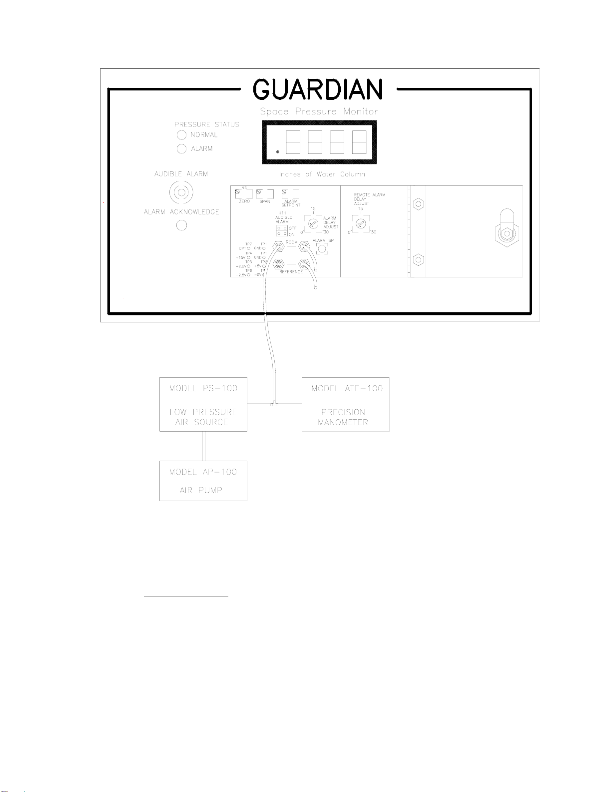
The Guardian is a complete system package consisting of space and reference pressure sensors and the
central signal processing module. The central module measures and displays the pressure differential
with a resolution of up to one ten thousandth of an inch water column. The LED display can be factory
set for engineering units of either Inches Water Column or Pascals. An analog output which is linear to
the pressure differential is provided for remote monitoring, control and data logging. An alarm
condition will occur when the space pressure falls outside the preset operating range. During an alarm
condition a local LED will illuminate, a local audible alarm circuit will be enabled, and an alarm relay
shall energize for remote alarming purposes. An optional remote auxiliary alarm is available with an
adjustable delay which will activate a local LED and the audible alarm. A key locked front panel
allows for controlled access to the field configurable functions of the Guardian. These functions
include pressure alarm setpoint adjustment, audible alarm on/off selection, adjustable delay of the
pressure alarm to prevent nuisance alarms which would occur due to normal foot traffic, and
differential pressure transducer calibration.
2.0 GUARDIAN FEATURES
2.1 POWER SUPPLY
The Guardian utilizes an isolated linear type power supply generating +15vdc and ∀5vdc to
power the pressure transducer sensor, scaling and digit circuitry. Input power to the Guardian
is 24VAC. The power supply is fused with a 3/8 Amp Slow Blow Pico fuse, located near the
input power terminal.
2.2 ALARM STATUS
Both Normal and Alarm operating status is locally indicated via LED•s on the Guardian face
plate.
2.3 ALARM SELECTION
The Guardian can be field configured to provide either Positive or Negative room pressure
alarming function. In the Positive mode the alarm activates when space pressure falls below
the alarm setpoint value. When in the Negative mode the alarm activates when space pressure
rises above the setpoint value.
2.4 AUDIBLE ALARM ACKNOWLEDGE
Muting of the local audible alarm during a loss of the required pressurization level. The
audible alarm circuit shall be reset once the monitored pressurization level is within the
acceptable operating range.
2.5 REMOTE ALARM RELAY
A single-pole double-throw relay is energized whenever the space pressurization level is
outside of the acceptable operating range.
2.6 REMOTE ROOM PRESSURE SELECT
The Room Pressure Monitor can be configured for positive or negative room monitoring
remotely by the closure of a dry contact.
2.7 REMOTE AUXILIARY ALARM

4
The auxiliary alarm can be activated either by a contact closure or contact opening. The alarm
can be delayed up to 30 seconds and will activate the audible alarm.
2.8 DISPLAY
The 3-1/2 digit LED is factory scaled to indicate the space pressurization level in engineering
units of either Inches Water Column or Pascals.
2.9 DISPLAY SELECTION
The 3-1/2 digit LED space pressure indicating meter is also utilized for indicating and
adjusting the Alarm Setpoint value by depressing a push button switch located under the
access door on the cover plate. Pressing of this push button toggles the indicated value
between space pressure and alarm setpoint. If the switch is not pressed for approximately 60
seconds the display will automatically defaults to indicate the measured space pressure.
2.10 KEY LOCKED ACCESS DOOR
The Key Locked Access Door allows for controlled access to Guardian configuration, alarm
setpoint display and adjustment, alarm delay on activation adjustment, activation/deactivation
of the local audible alarm, and differential pressure transducer calibration.
3.0 CENTRAL MODULE CONFIGURATION
(Refer to Figures 2 and 3 for jumper locations)
3.1 Equipment Required
3.1.1 Small Needle Nosed Pliers
3.2 Positive/Negative Space Pressure Alarming
3.2.1 Positive space pressure alarming is established by placing jumper H3/ALARM SP in
the + position, and jumper H4/SPACE in the POS position.
3.2.2 Negative space pressure alarming is established by placing jumper H3/ALARM SP in
the -- position, and jumper H4/SPACE in the NEG position.
3.3 Remote Positive/Negative Space Pressure Selection
3.3.1 To configure for remote space pressure selection, set H3 & H4 jumper to AUTO
position.
3.4 Audible Alarm Activation/Deactivation
3.4.1 To activate the local audible alarm function, place jumper H11/AUDIBLE ALARM in
the ON position.
3.4.2 To deactivate the local audible alarm function, place jumper H11/AUDIBLE ALARM
in the OFF position.
3.5 Analog Space Pressure Output Signal

5
3.5.1 To provide a 0 to 10vdc analog output signal for remote monitoring of the space
pressurization level place jumper H5/PROCESS in the V position.
3.5.2 To provide a 4 to 20mAdc analog output signal for remote monitoring of the space
pressurization level place jumper H5/PROCESS in the I position.
3.6 Process Output
1) Process Output signal can be changed between voltage or current by positioning H5 jumper
to I or V. The following table gives the jumper position and corresponding output selection.
H5 JUMPER
SELECTION
OUTPUT
SELECTION
I
V
4-20 MA
0-10VDC
TABLE 3.5 OUTPUT SELECTION
4.0 PRE-STARTUP CHECK
(Refer to Figure 1, 2 & 3 For Test Point and Adjustment Locations)
4.1 Equipment Needed
4.1.1 4-1/2 Digit Digital Multi Meter (Fluke Model 8062A Or Equivalent DMM)
4.1.2 Potentiometer Adjustment Tool (Spectrol)
4.2 Pre-Startup Check
4.2.1 With 24VAC power applied to the Guardian, Verify LED displays illuminate.
4.2.2 Monitor TP2 and verify a reading of +5.5 + .6 vdc.
4.2.3 Monitor TP3 and verify a reading of -4.8 + .6 vdc.
4.2.4 Monitor TP4 and verify a reading of +15 ∀.6 vdc.
4.2.5 Monitor TP5 and verify a reading of +2.5 ∀.1vdc.
4.2.6 Monitor TP6 and verify a reading of -2.5 ∀.1vdc.
4.2.7 Open access door and connect the positive (+) probe of DMM to TP7 (DPT) and the
common (-) probe to TP1 (GND). Disconnect one side of ROOM and REFERENCE
pneumatic tubing from fittings. Verify a reading of ∀0.005vdc. If out of
specification, adjust ZERO potentiometer (R4) for 0.000vdc + .001vdc.

6
FIGURE 1 TEST SET-UP
5.0 DIFFERENTIAL PRESSURE TRANSDUCER CALIBRATION PROCEDURE
(Refer to Figure 1 For Test Set-Up)
5.1 Equipment Needed
5.1.1 4-1/2 Digit Multi Meter (Fluke Model 8062A Or Equivalent DMM)
5.1.2 Precision Manometer (Ashcroft Model ATE-100 Or Equivalent)
5.1.3 Compressed Air source (Paragon Model AP-100 Air Pump)
5.1.4 Low Pressure Signal Generator (Paragon Model PS-100)
5.1.5 Potentiometer Adjustment Tool (Spectrol)

7
5.2 Calibration
5.2.1 Disconnect the pneumatic tubing from the left hand fitting labeled ROOM and
REFERENCE. This will produce a zero differential input pressure to the transducer.
Adjust the ZERO (R4) potentiometer for a reading of 0.000vdc, + 0.001vdc at TP7.
5.2.2 Obtain the full scale input range from the label located on the back of the access door.
With the pneumatic signal generator apply the required full scale pressure to the left
side ROOM pneumatic port. Adjust the SPAN (R10) potentiometer for a reading of
1.00vdc, + 0.001vdc at TP7.
5.2.3 Repeat steps 1 and 2 to verify that they meet specification tolerances. Large
adjustments to either zero or span may result in a slight shift in the other adjustment.
6.0 -2.5v REFERENCE, ANALOG OUTPUT AND DISPLAY SCALING CALIBRATION
Notes: 1. Removal of Guardian from the wall will be required to perform the following
calibration procedure.
2. All voltage measurements will be performed with DMM common (-) probe attached to
TP1.
3. Refer to Figure 1.0 for test set-up and Figure 2.0 & 3.0 for test point locations.
4. Analog output configuration (CURRENT or VOLTAGE) must be confirmed prior to
calibration. To determine the output configuration, refer to the label on the back side
of the access door and confirm by checking jumper H5/PROCESS.
5. For CURRENT output configuration, disconnect field wiring from J2/PROCESS-
OUT terminal. Place DMM in current mode, and install leads in series with field
wiring.
6.1 Equipment Needed
6.1.1 4-1/2 Digit Multi Meter (Fluke Model 8062A Or Equivalent DMM)
6.1.2 Precision Manometer (Ashcroft Model ATE-100 Or Equivalent)
6.1.3 Compressed Air source (Paragon Model AP-100 Air Pump)
6.1.4 Low Pressure Signal Generator (Paragon Model PS-100)
6.1.5 Potentiometer Adjustment Tool (Spectrol)
6.2 Calibration
6.2.1 Monitor TP6 and adjust R106(-2.5v ADJ) for a reading of -2.5 ∀.001v.
6.2.2 With zero input pressure to the transducer
6.2.2.1 CURRENT (Uni-Polar Range)- Adjust R89 (ZERO) for a reading of 4.0mA,
∀.01mA. CURRENT (Bi-Polar Range)- Adjust R89 (ZERO) for a reading
of 12.0mA, ∀.01mA.

8
6.2.2.2 VOLTAGE (Uni-polar Range)- Adjust R75 (ZERO) for a reading of
0.00vdc, ∀.01vdc between J2 PROCESS (OUT+) and (GND) terminals.
VOLTAGE (Bi-polar Range)- Adjust R75 (ZERO) for a reading of 5.00vdc,
∀.01 vdc between J2 PROCESS (OUT+) and (GND) terminals.
6.2.3 With full scale pressure applied to the high port (See label on back of access door)
6.2.3.1 CURRENT - Adjust R87 (SPAN) for a reading of 20.0mA.
6.2.3.2 VOLTAGE - Adjust R84 (SPAN) for a reading of 10.00vdc between J2
(OUT+) and (GND) terminals.
6.2.3.3 Adjust R38 (DISPLAY) for full scale value on the LED display.
6.2.4 Repeat steps 2 and 3 to verify that they meet specification tolerances. Large
adjustments to either zero or span may result in a slight shift in the other adjustment.

9
J4
J2
J1
ELECTRICAL CONNECTIONS
TRIPLE GANG DOUBLE DEEP
ELECTRICAL BOX (T&B PART NUMBER:
H3BD-3/4-1 OR EQUAL)
EXT.
ROOM PRESSURE CONNECTION
REFERENCE PRESSURE CONNECTION
SP.
POWER
24VAC
IN+
DETAIL A
CONTPROCESS
OUT+
GND
GND
GND
OUT+
REFERENCE
ROOM
PRESSURE
PANEL
MONITOR
ROOM
SENSOR
REFERENCE
PRESSURE
SENSOR
SEE
DETAIL A
AUXILIARY ALARM (OPTION)
ALARM
NC
COM
NO
REMOTE ALARM
NO
COM
NC
MONITOR PANEL MAY BE REQUIRED).
NA
NA
PROCESS OUTPUT(0-10VDC/4-20MA)
REMOTE POS/NEG SELECT (OPTION)
24VAC POWER
EARTH GROUND
(CONDUIT BETWEEN SENSORS AND
1/4"X.170 TUBE BARB
FIGURE 2

10
COMPONENT SIDE
REFERENCE
ROOM
24VAC
CONT. S.P. INPUT
F1
IN+
J1
REFERENCE PRESSURE CONNECTION
ROOM PRESSURE CONNECTION
GND
GND
OUT+
OUT+
GND
J2 H10 CL
OP
H2
R106
-2.5V ADJ.
TRANSFORMER
T1
CONT.
ALARM
ALARM SP
-
+
SP.
AUTO
H3
DISPLAY SPAN
SPAN
ZERO & SPAN
-2.5V
-5V
TP2
TP3
+5V
TP1
GND
GNDTP1
+2.5V
+15V
TP5
TP6
TP4
TP7DPT
ALARM
R84
NC
COM
NO
J4 INV
NON-
INV H1
RELAY
ZERO & SPAN
PROCESS CURRENT OUTPUT
PROCESS VOLTAGE OUTPUT
R38
R89
CURRENT
ZERO
R75
H5
R87
ZERO
VOLTAGE SPAN
CURRENT
SPACE
POS
NEG
AUTO
H4
REMOTE POS/NEG ROOM SELECT
REMOTE AUXILIARY ALARM
FIGURE 3
Table of contents
Popular Measuring Instrument manuals by other brands

Agilent Technologies
Agilent Technologies ESA-E Series Programmer's guide

Awite
Awite 10 Series Original instruction manual

MARTINDALE
MARTINDALE CMi210 instruction manual

Siemens
Siemens SITRANS FUE950 operating instructions

SellEton Scales
SellEton Scales OP-900 Series user manual

Delmhorst Instrument Co
Delmhorst Instrument Co G-34 owner's manual