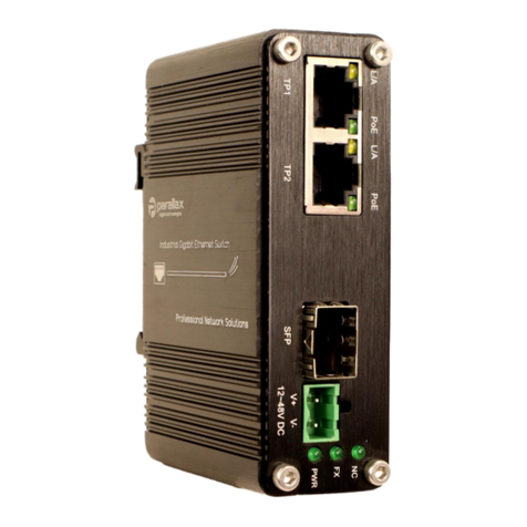
Parallax PDT-NSU-7104-MP-SF-I User manual

Operations Manual
PDT-NSU-7104-MP-SF-I
Revision 2.0 –March 2023

Table of Contents
1. Revision History..............................................................................................................................................2
2. Abbreviations..................................................................................................................................................3
3. Safety Information..........................................................................................................................................4
3.1 General Safety Information....................................................................................................................4
3.2 DC Power Supply ....................................................................................................................................4
3.3 Fibre-Optic Ports.....................................................................................................................................4
4. Packing List .....................................................................................................................................................5
5. Product Overview...........................................................................................................................................5
6. Connectors and Indicators..............................................................................................................................6
6.1 LED Indicators.........................................................................................................................................6
6.2 RJ45 Ports ...............................................................................................................................................7
6.3 Power Connections.................................................................................................................................7
6.4 PoE Output .............................................................................................................................................7
6.5 PoE Budget..............................................................................................................................................7
7. Installation Procedures...................................................................................................................................8
7.1 DIN Rail Installation ................................................................................................................................8
7.2 Wall Mount Installation..........................................................................................................................8
8. Connection and Setup ....................................................................................................................................9
8.1 Inspection Checks...................................................................................................................................9
8.2 RJ45 Connections....................................................................................................................................9
8.3 SFP Port Connections..............................................................................................................................9
8.4 Power Up ................................................................................................................................................9
9. Physical Dimensions .................................................................................................................................... 10
10. Hardware Specification ........................................................................................................................... 11

1.Revision History
Date
Rev
By
Comments
Checked
Date
20/09/2022
01
JF
Initial Release
SC
22/09/2022
02/03/2022
02
JF
Specification Updates
SC
02/03/2023

2.Abbreviations
Abbreviation
Description
AP
Access Point
CCA
Copper Clad Aluminium
DC
Direct Current
IEEE
Institute of Electrical and Electronic Engineers
IP
Internet Protocol
MTBF
Mean Time Between Failures
PD
Power Device
PoE
Power over Ethernet
PSU
Power Supply Unit

3.Safety Information
3.1 General Safety Information
Only trained and authorised personnel should be permitted to work on this equipment. It is
assumed that those using this guide are competent to work on equipment of this nature and will
take appropriate precautions when working with the fault analysis guide.
All devices should be inspected upon receipt for signs of physical damage, which may in turn, affect
operational performance, or the overall safety of the unit. Any damaged items should be returned
to Parallax Digital Technologies Ltd for safety checks.
Parallax Digital Technologies accepts no responsibility for any injury or loss caused by unsafe or
inadequate working practices, or for work carried out by an unauthorised third party.
To prevent possible danger, damage, and bodily harm when handling the equipment, please
observe all warnings, cautions notices contained in this section. Failure to heed the following
danger, warnings, and cautionary statements could lead to serious injury or death.
3.2 DC Power Supply
The Unit should be mains-fed using a DC Power Supply using an appropriately rated cable assembly,
which is protected internally at the power supply device itself. If the device is to be fed from an
alternative power source, then the appropriate circuit protection device should be used to ensure
that the supply circuit is interrupted, in the event that a fault in the device causes too much current
to flow into it, causing an unsafe condition.
3.3 Fibre-Optic Ports
This device incorporates Fibre Optic transmission ports –under no circumstance should anyone look
directly into these ports, as this may cause temporary or permanent damage to the user’s eyes.

4.Packing List
The following items are included in the shipping carton:
•1 x PDT-NSU-7104-MP-SF-I Unmanaged Ethernet Switch
•1 x DIN Rail Mounting Kit (Fitted)
•1 x Wall Mounting Kit
•Operation & Maintenance Manual (May be electronically supplied)
•Declaration of Conformity (May be electronically supplied)
5.Product Overview
The PDT-NSU-7104-MP-SF-I is a Small Form Factor Industrial Unmanaged Network Switch,
supporting 4 x 10/100/1000 BASE-T RJ45 Ports, and 1 x 100/1000 BASE-FX SFP Port, and the 4 x
RJ45 Ports are all PoE+ capable (802.3at).
This model can operate on input voltages from +12-48VDC, and the device has a voltage boosting
circuit to allow +48VDC to be supplied on the PoE output lines, even with a +12VDC supply
voltage.
The device is designed for use in harsh industrial environments, and incorporating a rugged
aluminium housing, it can be operated across a wide temperature range (-40°C to +80°C) making
it suitable for most conditions.
A typical application setup can be seen in the following diagram:

6.Connectors and Indicators
Front Panel
6.1 LED Indicators
The Front Panel LEDs display the status of the switch and the associated port connections as
indicated in the table below:
LED
Name
Colour
State
Status
PWR
Power Source
Green
OFF
Power Not Avail
ON
Power Available
FX
Fiber Link
Green
ON
SFP Connected
OFF
SFP Not Connected
L/A
Link Activity
Yellow
OFF
Not Running
ON
Running
PoE
Port Connection
Green
OFF
No Connection
Flashing
PD Detected
ON
PoE Established

6.2 RJ45 Ports
The Front Panel has 4 RJ45 Ports and which are all 10/100/1000 BASE-T Ports –note that these
are all PoE+ capable ports, in accordance with the IEEE 802.3at Standard. All of the RJ-45 ports
are auto MDI/MDI-X compatible and can operate in Full/Half Duplex Modes via auto-negotiation.
The remaining SFP port is 100/1000 BASE-FX and accept a wide range of SFP modules.
6.3 Power Connections
Model
V-
V+
Power Input
PDT-NSU-7104-MP-SF-I
GND
12-48VDC
Note: All Power Supplies should provide over-current and short-circuit protection and should
have a capacity rating to meet the required output current for the device.
6.4 PoE Output
Model
802.3af
802.3at
802.3bt
PDT-NSU-7104-MP-SF-I
●
●
6.5 PoE Budget
The total PoE Power Budget varies depending upon input voltage, as shown in the following table:
Supply Voltage
+12VDC
+24VDC
+48VDC
Total PoE Budget
60W
90W
120W

Press
Upper
part
Attach the Wall Mount Bracket (if not fitted)
to the switch case using the screws supplied
Mount the switch to the required surface
using appropriate fixings
7.Installation Procedures
7.1 DIN Rail Installation
7.2 Wall Mount Installation
Attach the DIN Rail Bracket (if not fitted) to
the switch case using the screws supplied
Clip the upper edge of the bracket onto the
DIN Rail and push to latch the bottom strip

8.Connection and Setup
8.1 Inspection Checks
Please inspect the unit to ensure that there is no damage to the external casing which could cause a
malfunction of the device or cause a safety critical fault. Any damaged units should be returned to Parallax
Digital Technologies for inspection and testing.
Please ensure that the DC Cables are securely fastened in the terminal block, and that the terminal block is
correctly inserted into the switch power connector housing.
8.2 RJ45 Connections
Ensure all required RJ45 Ports are connected correctly using CAT5e cable or better to the client devices.
The Uplink port should be connected to the host device or network, and the access ports TP1-4 are
available for other devices or connections. All cables should be solid copper and not CCA.
8.3 SFP Port Connections
Ensure that the SFP socket is clear from any dirt or contamination and that any required SFP Modules are
installed into the unit before applying power and care should be taken not to look directly into any open
port once power is applied. It is recommended to leave port blanks fitted when not in use. Only
compatible SFP modules should be installed in the unit and the maximum data thoughput for ports the
optical port is 1000Mbps.
8.4 Power Up
The Unit will automatically power up as soon as DC power is applied to the device. All LEDs will flash briefly
to complete the initialization sequence, then the Power LEDs- will be illuminate. Following this, the Port
Status LEDs and the Fiber indicator will display the current state of each of the ports.

9. Physical Dimensions

10. Hardware Specification
ETHERNET
Standards
IEEE 802.3 Ethernet
IEEE 802.3u Fast Ethernet
IEEE 802.3ab Gigabit Ethernet
IEEE 802.3x Full Duplex Flow Control
IEEE 802.3az Energy Efficient Ethernet
IEEE 802.3af Power over Ethernet
IEEE 802.3at Powe over Ethernet Plus
Forwarding and Filtering Rate
14,880pps (10Mbps)
148,800pps (100Mbps)
1,488,000pps (1000Mbps)
Packet Buffer
1Mbits
Packet Length
10KB
MAC Address Table
8K
Exchange Property
Backplane Bandwidth 20Gbps
Packet Forwarding Rate 14.88Mbps
INTERFACE
Wired
4 x 10/100 BASE-T RJ45
Fiber
1 x 1000 BASE-FX SFP
PoE
Standard
IEEE 802.3af/ IEEE 802.3at
Port Type
RJ45
Power Pin Assignment
4/5 (+) 7/8 (-)
Power Budget
48VDC Supply: 120W
24VDC Supply: 90W
12VDC Supply: 60W
ENVIRONMENTAL
Operating Temperature
-40°C to +80°C
Storage Temperature
-40°C to +85°C
Relative Humidity
5% - 95% non-condensing
MTBF
>200,000 hours
ELECTRICAL
Operating Voltage
12-48VDC (Terminal Block Connector)
Power Consumption
6W
Short-Circuit Protection
Auto-Reset
Reverse Polarity
Protected
MECHANICAL
Dimensions
95mm x 70mm x 29mm
Weight
250g
Casing
Aluminium
Mounting
DIN Rail & Wall Mount
INDICATORS
PWR
Power Status
FX
Fiber Port Status
L/A
Link Activity
SPD
Link Speed

CERTIFICATION
Electrical Safety
EN 62368-1:2020+A11:2020
Emissions
EN 55032:2015+A1:2020
Radiated Immunity
EN 55035:2017+A1:2020
Harmonic Emissions
EN 61000-3-2:2014
Fluctuations and Flicker
EN 61000-3-3:2013
Electro-Static Discharge
EN 61000-4-2:2009
Electromagnetic Field Immunity
EN 61000-4-3:2010
Electrical Fast-Transients
EN 61000-4-4:2012
Surge
EN 61000-4-5:2014+A1:2017
Conducted Immunity
EN 61000-4-6:2014
Power Frequency Magnetic Field
EN 61000-4-8:2010
RoHS
IEC 63000:2018
For all technical enquiries regarding this product, please contact our technical support team using the
following email address:
support@parallaxdigital.co.uk
This manual suits for next models
1
Table of contents
Other Parallax Switch manuals
Parallax
Parallax PDT-NSU-0008-MP-I User manual
Parallax
Parallax 27801 User manual
Parallax
Parallax ATS 5070 User manual

Parallax
Parallax ATS 5070 FI Manual
Parallax
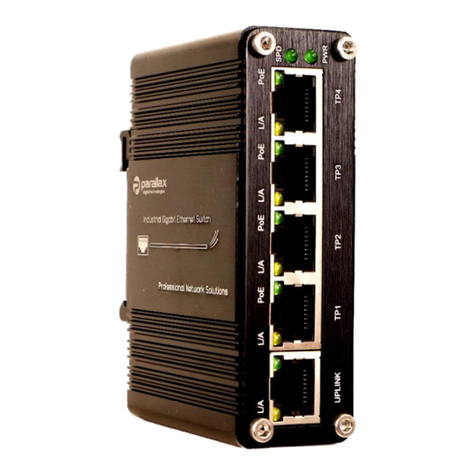
Parallax PDT-NSU-7005-MP-I User manual
Parallax
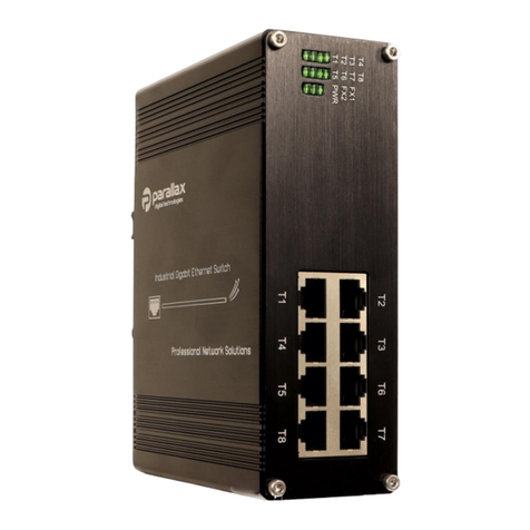
Parallax PDT-NSU-7008-MP-I User manual
Parallax
Parallax PDT-NSU-7208-MP-SF-I User manual
Parallax
Parallax PDT-NSU-7216-PA-SF-R User manual
Parallax
Parallax PDT-NSU-7105-MP-SF-I User manual
Parallax
Parallax PDT-NSU-0005-I User manual
