Parallel UPS 60 Series User manual

Parallel redundant & power system UPS 60..800kVA FXS – Operating manual
Sistema parallelo ridondante e di potenza UPS 60..800kVA FXS – Manuale operativo
Rev. Descrizione
Description Data
Date Emesso
Issued Controllato
Checked Approvato
Approved Lingua
Language Pagina
Page di Pag.
of Pag.
/ First Issue / Emissione 24.02.11
A Revision JSE414215 07.06.11
E/I 1 79
Codice / Code
JUD413937
PARALLEL REDUNDANT & POWER SYSTEM
UPS 60…800KVA FXS – OPERATING MANUAL
SISTEMA PARALLELO RIDONDANTE E DI POTENZA
UPS 60…800KVA FXS – MANUALE OPERATIVO

Parallel redundant & power system UPS 60…800kVA FXS – Operating manual
Sistema parallelo ridondante e di potenza UPS 60…800kVA FXS – Manuale operativo
2 of 79 JUD413937 Rev.A JSE414215 07/06/11
Index / Indice
ENGLISH LANGUAGE............................................................................... 7
1.INTRODUCTION.................................................................................. 8
2. PARTS THAT CONSTITUTE THE SYSTEM ...................................... 9
3. REDUNDANT PARALLEL SYSTEM .............................................. 10
3.1DESCRIPTION PARALLEL REDUNDANCY SYSTEM...................................10
3.2 OPERATIONAL STATUS PARALLEL REDUNDANCY ..............................10
3.2.1 ”N” UPS in normal operating mode....................................................11
3.2.2“N-1” UPS normal functioning mode..................................................12
3.2.3Mains fault.............................................................................................13
3.2.4“N” bypass available............................................................................14
3.2.5“N-1” bypass available.........................................................................15
3.2.5Manual bypass......................................................................................16
4. INSTALLATION PARALLEL REDUNDANT KIT.............................. 17
4.1 SUPPLEMENTARY HARDWARE................................................................17
4.2 FUNCTION....................................................................................................17
4.3 POSITIONING...............................................................................................17
4.4 INSTALLATION............................................................................................18
4.5 UPS CONFIGURATION................................................................................21
4.5 1Ups configuration parallel redundancy..............................................21
5. START UP AND CHECK OF THE PARALLEL SYSTEM................. 23
6. SYSTEM PERFORMANCE............................................................... 25
6.1 OVERLOAD..................................................................................................25
6.2 SHORT CIRCUIT..........................................................................................25
7. START-UP......................................................................................... 26
7.1 CASE OF 2 UPS – DIRECT START-UP.......................................................26
7.2 CASE OF 2 UPS – MANUAL BYPASS START-UP.....................................26
7.3 CASE OF N UPS – START-UP FROM MANUAL BYPASS.........................26
7.4 PROCEDURE FOR TRANSFERRING TO MANUAL BYPASS ...................27
7.5 PROCEDURE TO RETURN FROM MANUAL BYPASS..............................27
7.5.1Case of 2 or N UPS – Restart up from manual BYPASS ...................27
8. POWER PARALLEL SYSTEM......................................................... 28
8.1DESCRIPTION POWER PARALLEL SYSTEM...............................................28

Parallel redundant & power system UPS 60…800kVA FXS – Operating manual
Sistema parallelo ridondante e di potenza UPS 60…800kVA FXS – Manuale operativo
Rev.A JSE414215 07/06/11 JUD413937 3 of 79
8.2OPERATIONAL STATUS POWER PARALLEL SYSTEM.............................28
8.2.1“N” UPS normal condition...................................................................29
8.2.2Mains failure..........................................................................................30
8.2.3“N” bypass available...........................................................................31
8.2.4Manual bypass......................................................................................32
9. INSTALLATION REDUNDANT PARALLEL KIT.............................. 33
9.1 SUPPLEMENTARY HARDWARE................................................................33
9.2 FUNCTION....................................................................................................33
9.3 POSITIONING...............................................................................................33
9.4 INSTALLATION............................................................................................34
9.5 UPS CONFIGURATION................................................................................37
9.5 1Ups configuration parallel redundancy..............................................37
10.START UP AND CHECK OF THE PARALLEL SYSTEM ............... 39
11.SYSTEM PERFORMANCE.............................................................. 41
11.1 OVERLOAD..................................................................................................41
11.2 SHORT CIRCUIT..........................................................................................41
12. START-UP..................................................................................... 42
12.1START-UP FROM MANUAL BY-PASS.......................................................42
12.2MANUAL BY-PASS TRANSFER PROCEDURE .........................................42
12.3RE-START FROM MANUAL BY-PASS.......................................................43
LINGUA ITALIANA................................................................................... 44
1.INTRODUZIONE................................................................................ 45
2. PARTI CHE COSTITUISCONO IL SISTEMA.................................... 46
3. PARALLELO RIDONDANTE............................................................ 47
3.1DESCRIZIONE SISTEMA PARALLELO RIDONDANTE ................................47
3.2 STATI DI FUNZIONAMENTO PARALLELO RIDONDANTE .......................47
3.2.1“N” ups IN funzionamento normale....................................................48
3.2.2“N-1” ups funzionamento normale......................................................49
3.2.3Mancanza rete.......................................................................................50
3.2.4“N” bypass disponibili.........................................................................51
3.2.5“N-1” bypass disponibili......................................................................52
3.2.6 Bypass manuale ...................................................................................53
4.INSTALLAZIONE PARALLELO RIDONDANTE .............................. 54

Parallel redundant & power system UPS 60…800kVA FXS – Operating manual
Sistema parallelo ridondante e di potenza UPS 60…800kVA FXS – Manuale operativo
4 of 79 JUD413937 Rev.A JSE414215 07/06/11
4.1HARDWARE AGGIUNTIVO ............................................................................54
4.2FUNZIONI ........................................................................................................54
4.3POSIZIONAMENTO.........................................................................................54
4.4INSTALLAZIONE.............................................................................................55
4.5CONFIGURAZIONE DEGLI UPS.....................................................................58
4.5.1Configurazione degli UPS per sistemi parallelo ridondante.............58
5. AVVIO DEL SISTEMA DI PARALLELO RIDONDANTE E
VERIFICHE............................................................................................... 60
6.PRESTAZIONI DI SISTEMA ............................................................. 61
6.1SOVRACCARICO............................................................................................61
6.2CORTO CIRCUITO..........................................................................................61
7. AVVIAMENTO PER SISTEMA PARALLELO RIDONDANTE.......... 62
7.1 CASO DI 2 UPS – AVVIO DIRETTO............................................................62
7.2 CASO DI 2 UPS – AVVIO DA BYPASS MANUALE....................................62
7.3 CASO DI N UPS – AVVIO DA BYPASS MANUALE ...................................62
7.4 PROCEDURA DI TRASFERIMENTO SU BYPASS MANUALE ..................63
7.5 PROCEDURA DI RITORNO DA BYPASS MANUALE ................................63
7.5.1Caso di 2 o N UPS – Riavvio da BYPASS manuale............................63
8.PARALLELO DI POTENZA .............................................................. 65
8.1DESCRIZIONE SISTEMA PARALLELO DI POTENZA..................................65
8.2DESCRIZIONE SISTEMA PARALLELO DI POTENZA...................................65
8.2.1“N” ups IN funzionamento normale....................................................66
8.2.2Mancanza rete.......................................................................................67
8.2.3 “N” bypass disponibili.........................................................................68
8.2.4Bypass manuale ...................................................................................69
9.INSTALLAZIONE PARALLELO DI POTENZA................................. 70
9.1HARDWARE AGGIUNTIVO ............................................................................70
9.2FUNZIONI ........................................................................................................70
9.3POSIZIONAMENTO.........................................................................................70
9.4INSTALLAZIONE PARALLELO DI POTENZA ...............................................71
9.5CONFIGURAZIONE DEGLI UPS.....................................................................74
9.5.1Configurazione degli UPS per sistemi parallelo di potenza..............74
10. AVVIO DEL SISTEMA DI PARALLELO DI POTENZA E
VERIFICHE............................................................................................... 76

Parallel redundant & power system UPS 60…800kVA FXS – Operating manual
Sistema parallelo ridondante e di potenza UPS 60…800kVA FXS – Manuale operativo
Rev.A JSE414215 07/06/11 JUD413937 5 of 79
11.PRESTAZIONI DI SISTEMA............................................................ 77
11.1SOVRACCARICO.........................................................................................77
11.2CORTO CIRCUITO.......................................................................................77
12.AVVIAMENTO.................................................................................. 78
12.1 CASO DI 2 O PIÙ UPS – AVVIO DIRETTO .................................................78
12.2 CASO DI 2 O PIÙ UPS – AVVIO DA BYPASS MANUALE .........................78
12.3 PROCEDURA DI TRASFERIMENTO SU BYPASS MANUALE ..................78
12.4 PROCEDURA DI RITORNO DA BYPASS MANUALE ................................79
12.4.1Caso di 2 o N UPS – Riavvio da BYPASS manuale............................79
Index of pictures / Indice delle figure
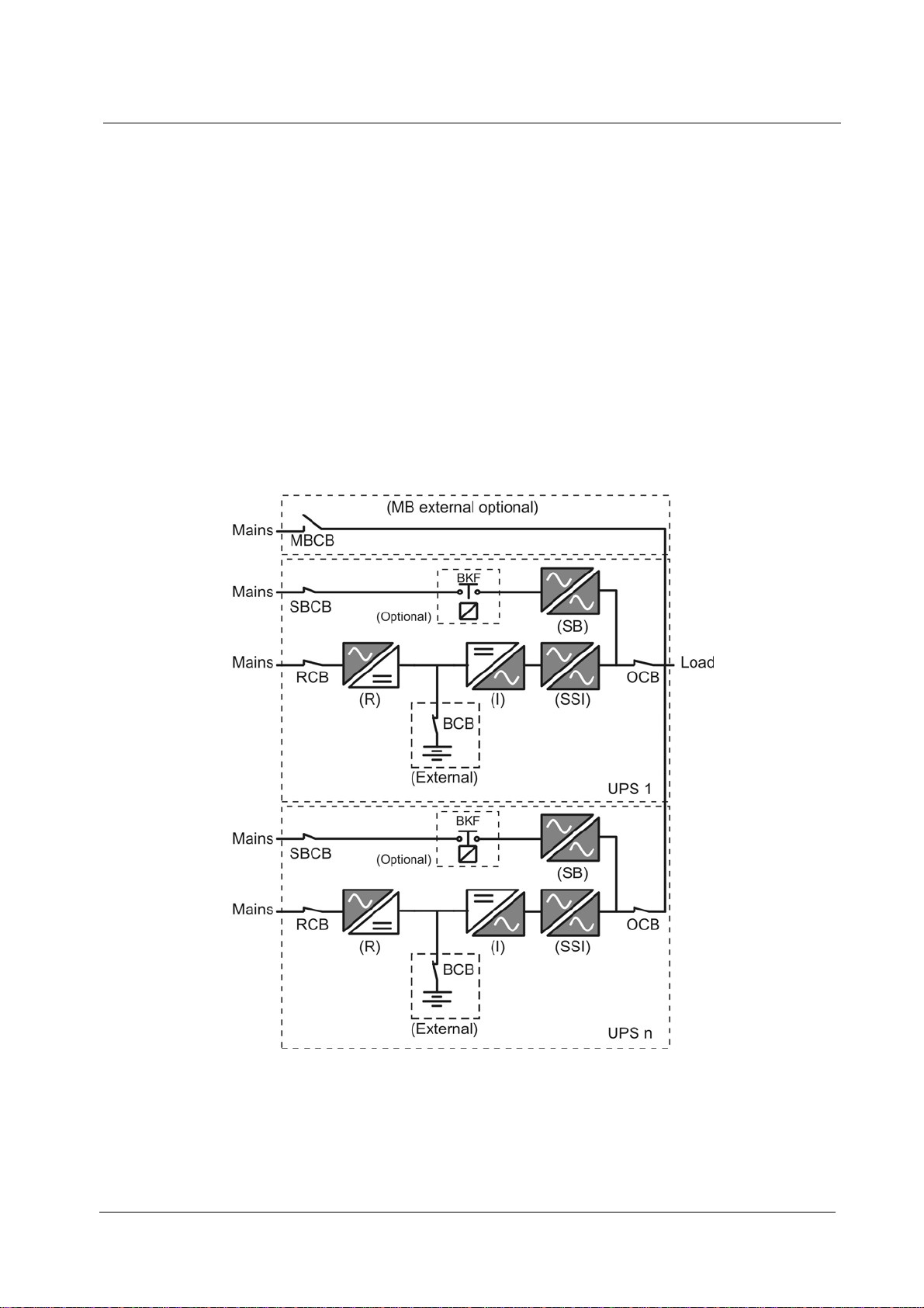
Picture 1 – Block diagram............................................................................................................................. 9
Picture 2 – “N” UPS in normal functioning mode ...................................................................................... 11
Picture 3 – “N-1” UPS in normal functioning mode .................................................................................... 12
Picture 4 – Mains failure............................................................................................................................. 13
Picture 5 – “N” bypass available................................................................................................................. 14
Picture 6 – “N-1” bypass available ............................................................................................................. 15
Picture 7 – Manual Bypass......................................................................................................................... 16
Picture 8 – Contents of the package.......................................................................................................... 17
Picture 9 – Slot-Par jumper setting............................................................................................................. 18
Picture 10 – Install the Interface and connect the cable ............................................................................ 19
Picture 11 – BUS-CAN connection 3 units 160kVA................................................................................... 20
Picture 12 – Connection UPS 3 units 500kVA ........................................................................................... 20
Picture 13 – Eproom Manager parameters setting parallel redundant ...................................................... 22
Picture 14 – “N” ups normal condition........................................................................................................ 29
Picture 15 – Mains failure........................................................................................................................... 30
Picture 16 – “N” bypass available............................................................................................................... 31
Picture 17 – Manual bypass....................................................................................................................... 32
Picture 18 – Contents of the package........................................................................................................ 33
Picture 19 – Slot-Par jumper setting........................................................................................................... 34
Picture 20 – Install the Interface and connect the cable ............................................................................ 35
Picture 21 – BUS-CAN connection 3 units 160kVA................................................................................... 36
Picture 22 – Connection UPS 3 units 500kVA ........................................................................................... 36
Picture 23 – Eproom Manager parameters setting parallel redundant ...................................................... 38
Figura 1 – Schema a blocchi...................................................................................................................... 46
Figura 2 – “N” UPS in funzionamento normale ......................................................................................... 48
Figura 3 – “N-1” UPS in funzionamento normale....................................................................................... 49
Figura 4 – Mancanza rete........................................................................................................................... 50

Parallel redundant & power system UPS 60…800kVA FXS – Operating manual
Sistema parallelo ridondante e di potenza UPS 60…800kVA FXS – Manuale operativo
6 of 79 JUD413937 Rev.A JSE414215 07/06/11
Figura 5 – “N” bypass disponibili................................................................................................................ 51
Figura 6 – “N-1” bypass disponibili............................................................................................................. 52
Figura 7 – Bypass Manuale........................................................................................................................ 53
Figura 8 – Contenuto della confezione....................................................................................................... 54
Figura 9 – Configurazione Jumper scheda SLOT-PAR............................................................................. 55
Figura 10 – Installazione scheda e connessione cavo flat......................................................................... 56
Figura 11 – Connessione CAN-BUS. Esempio con tre unità 160kVA....................................................... 57
Figura 12 – Collegamento di 3 unità UPS 500kVA................................................................................... 57
Figura 13 – Configurazione parametri Eproom per parallelo di ridondante.............................................. 59
Figura 14 – “N” UPS in funzionamento normale ....................................................................................... 66
Figura 15 – Mancanza rete......................................................................................................................... 67
Figura 16 – “N” bypass disponibili carico su linea di emergenza............................................................... 68
Figura 17 – Bypass Manuale...................................................................................................................... 69
Figura 18 – Contenuto della confezione..................................................................................................... 70
Figura 19 – Configurazione Jumper scheda SLOT-PAR ........................................................................... 71
Figura 20 – Installazione scheda e connessione cavo flat......................................................................... 72
Figura 21 – Connessione CAN-BUS. Esempio con tre unità 160kVA....................................................... 73
Figura 22 – Collegamento di 3 unità UPS 500kVA.................................................................................... 73
Figura 23 – Configurazione parametri Eproom per parallelo di potenza ................................................... 75

Parallel redundant & power system UPS 60…800kVA FXS – Operating manual
Sistema parallelo ridondante e di potenza UPS 60…800kVA FXS – Manuale operativo
Rev.A JSE414215 07/06/11 JUD413937 7 of 79
ENGLISH LANGUAGE

Parallel redundant & power system UPS 60…800kVA FXS – Operating manual
Sistema parallelo ridondante e di potenza UPS 60…800kVA FXS – Manuale operativo
8 of 79 JUD413937 Rev.A JSE414215 07/06/11
1. INTRODUCTION
The purpose of this manual is to guide the installer or user in the correct installation
of the parallel redundancy or power parallel system in the plant.
Before reading this manual, the user must carefully read the UPS
OPERATIONAL MANUAL and correctly follow the instructions for the individual
units, especially the safety requests according to CEI 64-8 and to 46-90.
The maker declines all responsibility for damages caused to persons or things,
deriving from the non-compliance of the above.

Parallel redundant & power system UPS 60…800kVA FXS – Operating manual
Sistema parallelo ridondante e di potenza UPS 60…800kVA FXS – Manuale operativo
Rev.A JSE414215 07/06/11 JUD413937 9 of 79
2. PARTS THAT CONSTITUTE THE SYSTEM
All the units are constituted by six functional operating sub-system:
-IGBT Rectifier (R)
-Inverter (I)
-Battery (B)
-Static Switch: Static Switch Inverter (SSI) e Static Bypass (SB)
-BKF optional (standard only for 400-500-600-800 kVA)
-Manual Bypass (MB) standard for 60-80-100-125-160-200-250-300kVA
mounted internal (can be also external), optional for 400-500-600-800kVA
mounted only external.
-Front Panel
For the description of the single parts, see: “UPS OPERATING MANUAL”
Picture 1 – Block diagram

Parallel redundant & power system UPS 60…800kVA FXS – Operating manual
Sistema parallelo ridondante e di potenza UPS 60…800kVA FXS – Manuale operativo
10 of 79 JUD413937 Rev.A JSE414215 07/06/11
3. REDUNDANT PARALLEL SYSTEM
3.1 DESCRIPTION PARALLEL REDUNDANCY SYSTEM
The parallel redundancy system is constituted by “N” UPS (up to a maximum of 5+1
units), configurated as redundant parallel units. In the UPS The Manual Bypass is
external and optional, and generally is only one for all units.
In addition to the standard functions of a UPS such as power continuity, protection of
the load from mains distortions etc., the parallel redundancy system guarantees a
continuity of power even if more than one system failure is ascertained.
This is possible because all the units are constantly operative and feed the load in
parallel, furnishing each with a current equal to “total load /n”, where “n” is the number
of the units that are being supplied at that moment.
The automatic distribution control of the AC current equalizes the currents of the “n”
units and reduces the unbalance to less than 10%, under all load conditions.
The load is fed by the parallel inverters even when an instantaneous overload “n x
200%” of the nominal load of every individual unit is verified.
In the event of a breakdown of one of the units, the load is fed by the others. Only in
the event that ulterior breakdowns are verified in the other units will the load be
transferred to the Emergency Mains (Bypass).
3.2 OPERATIONAL STATUS PARALLEL REDUNDANCY
If a breakdown occurs for which a UPS can no longer distribute on the load, during
the state of “n UPS in normal functioning”, the parallel redundancy system gets
transferred to the “n-1 UPS in normal operational status. Under these conditions, a
further irregularity of a UPS which prevents the feeding of the load, transfers the system
to the “Emergency Bypass Line, feed the load” condition, every additional irregularity,
may or may not, according to the type of irregularity, interrupt the feed to the load. The
irregularies are registered by each UPS with alarms and visualized on the same front
panel of the UPS.
In the event that a system mode has a rectifier breakdown or mains loss, in the “n
UPS in normal functioning”, the UPS will continue to distribute the load discharging the
battery, automatically isolating itself from the system until the end of the back-up time
and transfers the system to the “n-1” UPS normal operating mode.
If the system is transferred to the Manual Bypass (MB), the load gets fed directly
from the mains, therefore not guaranteeing the continuity of the load and the entire
parallel system becomes separated from the load.

Parallel redundant & power system UPS 60…800kVA FXS – Operating manual
Sistema parallelo ridondante e di potenza UPS 60…800kVA FXS – Manuale operativo
Rev.A JSE414215 07/06/11 JUD413937 11 of 79
3.2.1 ”N” UPS in normal operating mode
Load feed by inverter and possibility of a continuity breakdown.
Picture 2 – “N” UPS in normal functioning mode

Parallel redundant & power system UPS 60…800kVA FXS – Operating manual
Sistema parallelo ridondante e di potenza UPS 60…800kVA FXS – Manuale operativo
12 of 79 JUD413937 Rev.A JSE414215 07/06/11
3.2.2 “N-1” UPS normal functioning mode
Load on inverter and, in case of breakdown, transfer to bypass (if available).
Picture 3 – “N-1” UPS in normal functioning mode

Parallel redundant & power system UPS 60…800kVA FXS – Operating manual
Sistema parallelo ridondante e di potenza UPS 60…800kVA FXS – Manuale operativo
Rev.A JSE414215 07/06/11 JUD413937 13 of 79
3.2.3 Mains fault
Load on inverter feed by battery.
Picture 4 – Mains failure

Parallel redundant & power system UPS 60…800kVA FXS – Operating manual
Sistema parallelo ridondante e di potenza UPS 60…800kVA FXS – Manuale operativo
14 of 79 JUD413937 Rev.A JSE414215 07/06/11
3.2.4 “N” bypass available
Load on bypass in the event of at least two inverter breakdowns or overload.
Picture 5 – “N” bypass available

Parallel redundant & power system UPS 60…800kVA FXS – Operating manual
Sistema parallelo ridondante e di potenza UPS 60…800kVA FXS – Manuale operativo
Rev.A JSE414215 07/06/11 JUD413937 15 of 79
3.2.5 “N-1” bypass available
Load on bypass in the event of at least two inverter breakdowns or overload.
Picture 6 – “N-1” bypass available

Parallel redundant & power system UPS 60…800kVA FXS – Operating manual
Sistema parallelo ridondante e di potenza UPS 60…800kVA FXS – Manuale operativo
16 of 79 JUD413937 Rev.A JSE414215 07/06/11
3.2.5 Manual bypass
Picture 7 – Manual Bypass

Parallel redundant & power system UPS 60…800kVA FXS – Operating manual
Sistema parallelo ridondante e di potenza UPS 60…800kVA FXS – Manuale operativo
Rev.A JSE414215 07/06/11 JUD413937 17 of 79
4. INSTALLATION PARALLEL REDUNDANT KIT
Before installing the redundant parallel system, follow carefully the “INSTALLATION”
chapter in the “UPS OPERATING MANUAL” for the individual units, to be aware of all
the information regarding:
-Reception of UPS
-Size and weight
-Distance from walls
-Cable sections, fuses and terminal board
4.1 SUPPLEMENTARY HARDWARE
In order to transform “N” standard “Individual” unit into a redundancy parallel system,
it is necessary to obtain a Parallel N kit.
Each Parallel Kit contains:
-N. 1 Parallel interface card PB214 Rev.B or Higher SLOT-PAR (Pict. 8)
-N. 1 Connection cable CAN (DB9-DB9) (Pict.8)
-N. 1 Parallel Kit Manual
Picture 8 – Contents of the package
4.2 FUNCTION
The parallel-kit enables UPS’s designed as single units to be modified for parallel
operation. This procedure describes the connection and configuration of the system.
The working steps in this manual and the Operation-Manual for Paralleling must be
followed to ensure the correct installation and setup of the system.
4.3 POSITIONING
It is advisable to place the two UPSs at a distance of at least 10 cm from each other
in order to facilitate the passage of power and signal cables.

Parallel redundant & power system UPS 60…800kVA FXS – Operating manual
Sistema parallelo ridondante e di potenza UPS 60…800kVA FXS – Manuale operativo
18 of 79 JUD413937 Rev.A JSE414215 07/06/11
4.4 INSTALLATION
This description contains all information for the installation of the PCB into a single
unit.
For changing a single UPS into a parallel operational UPS it is necessary to mount
the Interface PCB in the UPS and repeat all the steps for each unit being part of the
parallel system.
Before starting the work it is necessary to stop each UPS and/or put the load into the
Manual-Bypass-Mode. For this step please refer to the Operating Manual.
ATTENTION
We strongly point out that the load is not supplied with a secure power-supply when
using the Manual-Bypass, a mains blackout could lead to an interruption of the power-
supply to the load.
After transferring the load to the Manual-Bypass and stopping the UPS, verify the
flat-cable W30C is fixed on the slot-plate. Connect the cable W30C to the connector
CN1 on the SLOT-PAR-PCB and mount the card with the two screws in the slot of the
UPS (see picture 10).
For a proper communication between all UPS it is mandatory to terminate the CAN-
Bus by using 120 Ohm-resistors. This is done using jumpers on the first and last UPS’S
in the system.
Configuration of the jumper of the SLOT-PAR-PCB in function of the amount of UPS
used in the parallel system:
N UPS System UPS1 UPS2 UPS3 UPS4 UPS5 UPS6
2 JP1 Closed
JP2 Closed JP1 Closed
JP2 Closed
3 JP1 Closed
JP2 Closed JP1 Open
JP2 Open JP1 Closed
JP2 Closed
4 JP1 Closed
JP2 Closed JP1 Open
JP2 Open JP1 Open
JP2 Open JP1 Closed
JP2 Closed
5 JP1 Closed
JP2 Closed JP1 Open
JP2 Open JP1 Open
JP2 Open JP1 Open
JP2 Open JP1 Closed
JP2 Closed
6 JP1 Closed
JP2 Closed JP1 Open
JP2 Open JP1 Open
JP2 Open JP1 Open
JP2 Open JP1 Open
JP2 Open JP1 Closed
JP2 Closed
Picture 9 – Slot-Par jumper setting

Parallel redundant & power system UPS 60…800kVA FXS – Operating manual
Sistema parallelo ridondante e di potenza UPS 60…800kVA FXS – Manuale operativo
Rev.A JSE414215 07/06/11 JUD413937 19 of 79
Picture 10 – Install the Interface and connect the cable
The connection between all units involved is done by the CAN-BUS cable supplied
with the kit.
Starting from the first unit, the cable is connected to “PAR CAN-OUT”. It goes to the
second unit “PAR CAN-IN”.
If more then two units are configured for the parallel-system, some additional cable
must be connected in the same sense: A second cable goes from the second unit “PAR
CAN-OUT” to the third unit “PAR CAN-IN” etc.
For Example: For 4 UPS, start the connection from UPS1 to the UPS2, from UPS2 to
the UPS3, then from UPS3 to UPS4 and finally from UPS4 return to the UPS1 making a
ring.
ATTENTION
Check accurately that the CAN-BUS cable is connected to the SLOT-PAR and not
other DB9 ports present on the rear of the UPS. A wrong connection may be result in a
damage of the interface card or/and the unit.

Parallel redundant & power system UPS 60…800kVA FXS – Operating manual
Sistema parallelo ridondante e di potenza UPS 60…800kVA FXS – Manuale operativo
20 of 79 JUD413937 Rev.A JSE414215 07/06/11
Picture 11 – BUS-CAN connection 3 units 160kVA
Picture 12 – Connection UPS 3 units 500kVA
Table of contents
Languages:
Other Parallel Power Supply manuals