Parish PANTHER 15B User manual

OWNER’S MANUAL
IMPORTANT: READ OWNER’S MANUAL CAREFULLY
MODEL # PANTHER 15B MICRO SCRUBBER
FORYOURCONVENIENCE,RECORDTHEFOLLOWING
IMPORTANTINFORMATION
MODEL:___________________________________
SERIALNUMBER:____________________________
DATEPURCHASED:___________________________
PURCHASEDFROM:__________________________

30
Warranty
Troubleshooting 29
Wiring Diagram 28
Parts Breakdown & Lists 9-27
Techinical Data 8
TABLE OF CONTENTS
Safety Precautions 1
Machine Set Up & Installation 2-4
Machine Operation 4-5
Maintenance 5-6
Battery Charging 6
Preventative Maintenance 7

Avoid moving parts. Do not wear loose
an cause explosion or fire. Do not pick up.
in tanks.
sparks and open flames away! Keep battery
Batteries emit hydrogen gas. Explosion or fi
not intended for any other use. Us l use. It is constructed for usThis machine is intended for commercia
SAFETY PRECAUTIONS
e in an indoor environment and is
e only with recommended accessories.
All operators shall read, understand and exercise the following safety precautions:
1) DO NOT OPERATE MACHINE:
Unless trained and authorized.
Unless you have read and understand the operators manual.
In flammable or explosive areas.
In outdoor areas.
2) BEFORE OPERATING MACHINE:
Make sure all safety devices are in place and operate properly.
3) WHEN USING MACHINE:
Go slow on inclines and slippery surfaces.
Follow all safety guidelines.
Be very careful when using the machine in reverse.
Report and fix any damage to machine prior to operating it.
4) BEFORE LEAVING OR SERVICING MACHINE:
Stop machine on level ground.
Turn machine off.
5) WHEN SERVICING MACHINE:
Read operators manual thoroughly prior to operating or servicing this machine.
Use manufacturer supplied or approved replacement parts.
Secure machine with wheel blocks prior to jacking the machine up.
Use approved jack or hoist to safely elevate the machine.
Disconnect batteries prior to working on machine.
Wear gloves when handling batteries or battery cables.
Avoid any contact with battery acid. fitting clothing while servicing machine.
WARNING!
WARNING!
WARNING!
1
re can result from hydrogen gas. Keep
compartment open when charging.
Flammable materials can cause an explosion or fire. Do not use flammable materials
Flammable materials or reactive metals c
If not in proper operating condition.

the squeegee up (33).
Be sure batteries are fully charged (see Battery Charging section).
if equipped if equipped
if equipped
d in figure 2. Pull up the lift lever (26) to raise
1. Turn off the machine.
Brush/Pad Driver Installation and Disassembly
Lower the squeegee (33) with the lift lever (26).
Pre-operation Checks
Charge the batteries (see battery charging section).
WARNING!
7. Brush or pad driver
6. Connecting wire for battery and charger
5. Electric Battery Charger Manual
2. Batteries (x2)
MACHINE SET UP & INSTALLATION
BATTERY DISASSEMBLY AND INSTALLATION
2
UNCRATING MACHINE
Be sure and check packing carton for any damage. Immediately report any damage to carrier.
Check contents of package to ensure that the following items are included:
1. Machine
3. Squeegee assembly
4. Scrubber-dryer User Manual
1. Switch off the main switch (47).
2. Remove the recovery tank (2) as shown in the relevant paragraph.
3. Unscrew the bolt from batteries (16), then remove or change.
4. Install the batteries on the machine according to the diagram below.
5. Install the recovery tank.
Do not connect+ to +,or - to-,when disassembly or install the batteries. It is very dangerous.
Battery charging
MACHINE SET UP
1.Sweep or dust mop the surface to be cleaned.
2.Check that squeegee is properly installed.
3.
4.
5.Check that brush/pad is properly installed.
NOTE
2. Lay down the machine in this position as indicate
Only install manually. If auto-installation, it will wear brush hub.
Make sure that the tanks are empty before disassembling the brush.
Figure1

Tighten the knobs securely (unscr
. The brush/pad could disengage and cause injury.
with a pipe or bucket. Do not remove the Solution Filter (21) whileThe machine can be filled
Solution Tank Filling
(56/57), unscrew the thumb nut (37).
ew the knobs, if disassembling).
slide the squeegee into the slots of the squeegee
ion as indicated in figure 2.
down the squeegee on the “working” position.
Turn off the main switch (47).
Squeegee Installation
Do not turn on the machine in th position shown belowe
WARNING!
locks, as indicated in figure 3.
brackets.
3
3. Mount the brush or pad driver onto the drive wheel hub and then rotate counterclockwise until it
1.
2.Pull down the squeegee lift lever (26) to put
3.Lay down the machine in this posit
4.Loosen the two knobs (55) on the squeegee and
5.To replace the front/rear squeegee
NOTE
Figure3
Figure2
hub.
4. To remove the brush/pad,rotate the brush/pad clockwise until it is released from drive wheel
filling.

When cleaning excessively aggressive floors this may cause the machine to not work.
ain cap (22) to let water pour out to a
cleaned after each scrubber operation is
and turn the latch (17) to lock the tank.Replace the recovery tank on the machine
he control panel (46).
means the machine is being overloaded.
This
indicators on the control panel (46) will flash simultaneously.
rush motor and vacuumB
Before lifting the brush, turn it off by pressing the main switch (47).
Move the machine and start cleaning.
Pull one or both operating triggers (24), and then brush
turning the solution flow control lever (31) manually.
tion switch (50), the indicate light will be on.
Turn on the main switch (47). pulling down the squeegee lift lever (26).
Set the handle to a comfortable height by pressing handle rotate lever (25).
dirty water into a container, or unscrew the solution tank dr
Turn the latch (17) off the recovery tank, ta
Solution Tank Draining
Clean and rinse the recovery tank
bucket.
Open the lid (1) and overturn the recovery tank to drain the
Recovery Tank Draining
Screw on the solution tank drain cap (22).
the solution tank. The solution/water
will flow freely into a bucket or floor drain.
Unscrew the solution tank drain cap (22) on the bottom of
the inlet (20) through pipe or bucket.
build up and clogging of the solution lines.
intended for automatic scrubber applications.
4
Turn on the vacuum motor switch (49), the indicate light will be on.
1. Fill water into solution tank (3) from
2. Do not fill the solution tank completely, leave a few centimeters from the edge.
3. The water temperature must not exceed 40 .
NOTE
1.
2.Rinse the solution tank with clean water after every use. This will help prevent chemical
3.
NOTE
1.ke off the recovery tank from machine by
grasping two grooves of tank.
2.with clean water after every use.
3.
MACHINE OPERATION
1.
2.
3.
4.Turn on the brush motor switch (48) and the solu
5.
6.If necessary, adjust the water flow by
7.
NOTE
.
CAUTION!
CAUTION!
Solution tank should be drained and
completed.
Recovery tank should be drained and cleaned after each scrubber operation is
completed.
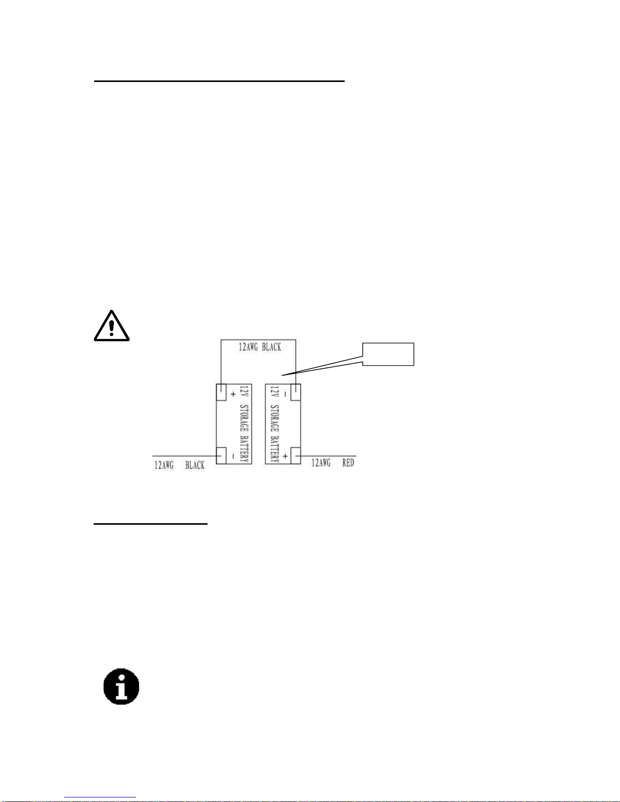
If the battery indicator light (51) is green, the machine can be used. If it is yellow or red, the
batteries must be charged.
CAUTION!
Use only low-foam and non-flammable detergents,
Lower the squeegee (33) onto the floor by
will start to spin, solution will begin to flow.
Please turn offall the switches on t
℃

This manual describes the easiest
1. Perform the procedures shown above in
Table, refer to the
Service
and most common maintenance
procedures.
arefully read the instruction in the Safety precaution section.charger cable disconnected. C
WARNING!
(After Using the Machine section).
DO NOT USE MACHINE FOR A LONG TIME
than 30 days, please procee
warranty.
machine prior to storage. Any damage caused by fr
with the brush/pad holder and the squeegee.
tenance section).
1. Remove the brush/pad holder.
2. Empty the tanks as shown in the previous paragraph.
5
CAUTION!
Do not use the machine with discharged batteries to avoid damaging the batteries and reducing the battery
life.
AFTER USING THE MACHINE
After scrubbing, please proceed with below actions before leaving the machine:
3. Perform the daily maintenance procedures (see the main
4. Store the machine in a clean and dry place,
5. If storing in an area which may reach freezing temperatures, be sure to drain all fluids from the
eezing temperatures will not be covered by the
If the machine is not going to be used for more d with below actions:
2. Disconnect the battery connector.
MAINTENANCE
The lifespan of the machine and its maximum operating safety are ensured by correct and regular
maintenance. The following chart provides the scheduled maintenance. The intervals shown may
vary according to particular working conditions, which will be defined by the person in charge of the
maintenance.
Maintenance procedures must be performed with the machine switched off and the batteries/battery
All scheduled or extraordinary maintenance procedures must be performed by qualified personnel, or
by an authorized Service Center.
For other maintenance procedures shown in the Scheduled Maintenance
Manual that can be consulted at any Service Center.
SCHEDULED MAINTENANCE TABLE
Inlet filter cl
Procedure
After each use Weekly Every six
months
Annually
Battery charging
Squeegee cleaning
Brush cleaning
Clean tank, vacuum screen & check top cover
gasket
Squeegee blade check and replacement
eaning

it's charging, green light means battery charging5. The charging indicator light (30) turns on when
(2). Exposing battery compartment.
1
Keeping the batteries charged makes battery life last longer.
relevant section.
Please use appropriate charger to charge the battery.
Charge the batteries when the yellow or red indicator (51),or at the end of every working cycle
by an authorized Service Center.
After the first 8 working hours.
machine socket. Connect the charging cable to the
he grounded wall outlet (100v~240v).
6. Upon the completion of charging, first unplug
7.
6
This maintenance procedure must be performed
BATTERY CHARGING
NOTE
CAUTION!
CAUTION!!
If the machine is not equipped with on-board battery charger, choose an external battery charger
suitable for the type of batteries installed.
WARNING!
1. Place charger and machine in a well ventilated area.
2. Turn machine off (47).
3. Take away the recovery tank
4. Plug the charging cable to t
is completed. the charging cable from the wall outlet and then
disconnect from machine.
Replace the recovery tank .
NOTE
For further information about the operation of the battery charger (29), see the
.
˄ ˅
˄
2
˅
Screw and nut tightening check ˄1˅
Lubricate rotary parts ˄1˅
Check brush motor carbon brushes ˄2˅
Check vacuum motor carbon brushes ˄2˅

4. Take off all vacuum kits, gasket, filter, clean and re-install.
(37) to remove the blades.
the vacuum rubber connector (18) between two tanks
as shown in Machine set up section.
BRUSH/PAD DRIVER CLEANING
s. Replace if necessary.
3. Unscrew the thumb nut
are integrity or not.
7
SQUEEGEE CLEANING
NOTE
CAUTION !
It is advisable to wear protective gloves when cleaning the squeegee because there may be sharp debris.
SQUEEGEE BLADE CHECK AND REPLACEMENT
1. Take off the squeegee as shown in the previous paragraph.
5. Install the squeegee in the reverse order of removal.
CAUTION!
It is advisable to wear protective gloves when cleaning the brush/pad because there may be sharp debris.
2. Clean and wash the brush/pad with water and detergent.
3. Check the brush bristles for integrity and wearing status; if necessary, replace the brush.
4. Check the pad for wearing status; if necessary, replace the pad driver.
TANK/VACUUM GRID WITH FLOAT CLEANING AND COVER GASKET
CAUTION!
It is advisable to wear protective gloves when cleaning the tank and vacuum/suction assembly because there
may be sharp debris.
1. Move the machine to the appointed disposal area.
2. Turn off the main switch (47).
3. Take off the recovery tank (2), clean and rinse both solution/recovery tank, and drain out.
5. Check the recovery tank lids gasket ring and
NOTE
The gasket ring of recovery tank and the rubber connector between two tanks create
vacuum in the tank. If necessary, replace them. .
a good drying performance.
The squeegee must be clean and its blades must be in good condition in order to getting
are cracked or split, if necessary replace them with new.2. Check to see if the edge of the front/rear blades
4. Check the front/rear blades for integrity, cut and tear
1. Remove the brush/pad

Sound level 68dBA
Machine length x width x height 770x500x550MM
Control Panel
Vacuum motor data 24V 300W
Input 100-240
Carton spec 780x415x590MM
8
54
53
52
51
Vacuummotorswitch
Brushmotorswitch
Mainswitch
Control panel
46.Electric quantity indicator
47.Brush motor indicator
48.Vacuum motor indicator
49.Suction Electromagnetic valve data indicator
50.Suction Electromagnetic valve data switch
TECHINICAL DATA
Solution tank capacity 15L
Recovery tank capacity 15L
Wheel diameter 254MM
Brush motor data 24V 250W
Electromagnetic valve data 24V
Maximum gradient 2%
Batteries data 2×12V24V 33Ah/20h
Power cable length /
Batteries spec 196 x 130 x 175mm
Working capacity, up to 800mm
Cleaning productivity 750m2/hour
Squeegee width 490mm
Brush diameter 380mm
Brush rpm 150rpm
Charger Vac,50-60HZ
Output 24Vdc,5A
Machine weight 60kg
Machine weight(with charger and
package) 65kg
.
.
.
.

9
PARTS BREAKDOWN
32
31 33
37
56
57
30
29
28
27
26
24
25 41
42
45
44
43
40
3938
8
2322
20
21
1819
9
16
17
15
14
13
12
11
10
3
4
7
6
5
2
1
36
22
35
34
59
58
33

10
PARTS BREAKDOWN
Screw nut
Squeegee adjustment piece
Rear squeegee
Front squeegee
Knob
59.
58.
57.
56.
55.
29. Battery Charger
35. Squeegee hose
34. Squeegee wheels
1. Recovery tank lid
2. Recovery tank
3. Solution tank
5. Protective rollers
6. Brush
7. Front handle shell
8. Control panel
9. Rear handle shell
10. Handle rubber
11. Handle iron pipe
12. Squeegee vacuum assembly
13. Squeegee suction assembly
14. Left positioning
15. Right positioning
16. Batteries
17. Latch
18. Rubber sealing
19. Limit hose joint
20. Inlet
21. Solution filter
22. Solution tank drain
23. Wheels on fixed axle
24. Handle left and right
25. Handle rotate lever
26. Squeegee lift lever
27. Squeegee string
28. Box circuit
30. Battery charge indicator
31. Solution flow control lever
32. Electromagnetic valve data
33. Squeegee
36. Axle
37. Thumb nut
38. Vacuum system motor
39. Brush motor
40. Drive belt
41. Belt
42. Squeegee rotation plate
43. Squeegee lift plate
44. Squeegee fixing plate
45. Motor fixing plate
cover4. Brush
54
53
52
51
Vacuummotorswitch
Brushmotorswitch
Mainswitch
Control panel46.
Electric quantity indicator
47.
Brush motor indicator
48.
Vacuum motor indicator
49.
Suction Electromagnetic valve data indicator
50.Suction Electromagnetic valve data switch
.
.
.
.

11
76
6 5
cCOMPLETE ASSEMBLY
47
58
2 6
4 2
4 3
1 6
7
8
9
1 0
1 1
1 2
1 3 1 5
1 6
1 7
1 8
1 9
2 0
2 22 32 4 2 9
3 0
2
1 4
1 4
3 3
3 4
3 5
3 6
3 8
3 9
4 0
4 1
4 5
4 4
5 2
3 2
3 1
2 4
5
6
6 6
2 1
5 3
5 5 5 65 75 9
5 4
3 7
6 0
2 5
2 6
2 7
2 8
5 2
PART LIST
PART LISTPART LISTPART LIST
63
62
64
13
15
61
3
4
5
4 6
4 8
5 0 4 9

12
COMPLETE(MACHINE(‐(FANG15B
1PIPE SI, D6XD10, 0.45MVF89846
1
PIPE SI, D4XD8, 0.115MVF89848
PIPE SI, D6XD10, 0.115MVF89847
VF89023US
VF89840
VF89817
VF89830
1
1
VF89821
VF89831
Item Part No. Description Qty
1 VF89100-SSS KIT, SOLUTION TANK 1
2 VF89018SSS LABEL, SOLUTION TANK 1
3 VF89200 KIT, AXLE WHEEL 1
4 VF14251 BOLT, M8X30, HEX HEAD 2
5 VF13514A WASHER, D8X1XD16.5 5
6 VF14516 NUT, NYLON INSERT, M8 4
7 KIT, MOTOR MOUNTING PLATE 1
8 VF85698 HEX SOCKET SCREW, M8X55 2
9 VF89030 BUSHING 2
10 VF14258 HEX SOCKET SCREW, M8X40 1
11 VF14503 NUT, M8 1
12 VF89400 KIT, SKIRT ASSEMBLY 1
13 VV13664 WASHER, D4X1XD8 15
14 VF13491 PH SCREW, M4X12 15
15 KIT, SQUEEGEE 1
16 VF89029A HOSE, CONNECT SQUEEGEE 1
17 VF85420 THUMB SCREW 2
18 KIT, HANDLE ASSEMBLY 1
19 VF89001 HANDLE BLOCK, LEFT 1
20 VF89002 HANDLE BLOCK, RIGHT 1
21 VF89003 CIRCUIT BOX 1
22 VV60220S1 HEX SOCKET SCREW, M6X15 8
23 VV20290 WASHER LOCK, ¢6 8
24 VF13614 WASHER, ¢6 14
25 GT13027 PH SCREW, M5X45 1
26 VA13482 WASHER, D5X1XD10 6
27 VF89004SSS LATCH, RECOVERY TANK 1
28 VF89005 SPRING, PRESS 1
29 KIT, CHARGER 1
30 VF89025-1 PLATE, MAIN CONTROL 1
31 VF89006 CIRCUIT COVER 1
32 VF14301 SCREW, M4X12 2
33 VF89034 HEX BOLT M6X50 4
34 VF89052 COVER, WATERPROOF 1
35 VF89037 PLUG, RUBBER 1
36 VF89035 COVER NUT, M6 6
37 VF89016 LABEL, CHARGE DISPLAY 1
38 VF89012 HANDLE GRIP, RUBBER 2
39 VF89017SSS LABEL, REAR HOUSING 1
40 VF89007 CABLE, SQUEEGEE LIFT 1
41 VF89008 HANDLE, SQUEEGEE LIFT 1
42 VV20509 PH SCREW, M5X10 3
43 VF89010 ROTATE AXLE, SQUEEGEE LIFT CABLE 2
44 VF89011 AXLE, SQUEEGEE LIFT CABLE 1
45 VF89009A ROTATE AXLE, SQUEEGEE LIFT CABLE
46 VF89056 SOLENOID VALVE, 24V 1
47 VF14514 NUT, NYLON INSERT, M5 1
48 VF89033 HOSE
49
50
51
BRUSH ASSEMBLY 1
PAD DRIVER 1
52
VF89007-1 CABLE, SQUEEGEE LIFT 1
2
VF89034A HEX BOLT M6X55 2
-SSS-SSS

13
COMPLETE(MACHINE‐FANG15B
67
65
SCREW, M5X12
Item Part No. Description Qty
53 VF85102 SMALL CLAMP 1
54 VF89055 RUBBER PLUG, CHARGER INSERT 1
55 VF89020 BATTERY, 2-12V 35Ah 1
56 VF89036 POWER WIRE 1
57 VF89021 KIT, BATTERY CONNECT LINE 1
58 VA13473 PH SCREW, M4X16 5
59 VF89827 KIT, RECOVERY TANK 1
60 VF85141 BIG CLAMP 1
61 VA13472 PH SCREW, M4X8
62
63
VS00001
VS00002
1
1
SUPPORT,LEFT
SUPPORT,RIGHT
64 GT13054 2
VV13650A SCREW, M4X10 11
66 VF14214 SCREW, M5X8 1
VF89015 PLATE 6
-SSS-SSS

14
SOLUTION TANK ASSEMBLY
1
10
11
13
14 15
8
9
4
12
18
3
5
6
16
17
2
7
19
20 21 22 23
PART LIST
PART LISTPART LISTPART LIST

15
VF89100-SSS
Item Part No. Description Qty
1 VF89101SSS SOLUTION TANK 1
2 VF89102 HOSE, CONNECT VACUUM
3 VF89103 SPRING, PRESS 2
4 VF89104 VACUUM HOSE
5 1
6 VF89106 PLASTIC PLATE, HOSE LIMIT 1
7 VF89107 RUBBER SEAL 2
8 VF89115 GASKET 1
9 VF89110 CAP, DRAIN 1
10 VF85302 RUBBER BUSHING 1
11 VF89091 SOLUTION TAP 1
12 VF89112 CABLE BRACKET 1
13 VF14200 PH SCREW, M6X15 2
14 VF89113 SEAT, INLET, FRESH WATER TANK 1
15 VF89114 FILTER, INLET, FRESH WATER TANK 1
16 VF13491 PH SCREW, M4X12 3
17 VV13664 WASHER ¢4 3
18 KIT, SOLUTION TANK 1
19 VF89201 WHEEL AXLE 1
20 VF89202 DRIVE WHEEL, 10" 2
21 VF14563 WASHER,WAVE 2
22 VF14552 SNAP SPRING 2
23 VF89202-3 CAP, WHEEL 2
VF89200 KIT, WHEEL AXLE
SOLUTION(TANK(ASSY(‐(FANG(15B
2
2
-SSS-SSS

16
BRUSH DECK ASSEMBLY
15 1 8
1 7
2 5
2 8
2 7
2 6
2 4
2 1
2 0
1 2
1 5
2 3
1 1
3
2 2
5
6
7
8
9
1 0
2
4
1 9
2 9
1
3 0
1 3
3 1
1 6
1 4
1 7
3 3
3 4
3 5
3 6
3 7
3 8
3 2
3 9
4 0
PART LIST
PART LISTPART LISTPART LIST
42
41

17
VF89823
Item Part No. Description Qty
1 VF89301 PLATE, MOTOR MOUNT 1
2 VF89302 BRUSH MOTOR ASSEMBLY 1
3 VF89303 SCREW, M6X14 4
4 VF89304 BOLT, DIRVE BELT 1
5 VF89305 O-RING, BIG 1
6 VF89306 SEALING COVER, VACUUM 1
7 VF89307 O-RING, SMALL 1
8 VF89309 KIT, VACUUM MOTOR 1
9 VF89310 BRACKET, VAC MOTOR 2
10 VF13491 PH SCREW, M4X12 3
11 VF89311 WASHER, THIN 1
12 VF89312 PLATE, SQUEEGEE ROTATE 1
13 VF89313 GUIDE WHEEL, SQUEEGEE 2
14 VA13482 WASHER ¢5 2
15 VA13475 PH SCREW, M5X25 3
16 VF14514 NUT, NYLON INSERT, M5 2
17 VF89314 KIT, BELT ADJUSTMENT 1
18 VF14223 SCREW, M6X25 1
19 VF14506 NUT, NYLON INSERT, M6 4
20 VF13614 WASHER, ¢6 3
21 VV20058 BOLT, M6X25, HEX 1
22 VF89318 SPRING 1
23 VF89319 BUSHING, SQUEEGEE ROTATE 1
24 ZD45425 BEARING, 6204 2
25 VF89320 BUSHING 1
26 VF89321 DRIVE HUB 1
27 VF89322 NUT, M20 1
28 VF89323 DRIVE BELT, PJ270 1
29 VF89324 PLATE, SQUEEGEE LIFT 1
30 VF89325 PLATE, SQUEEGEE BRACKET 1
31 VF89326 ROTATE BOLT, SQUEEGEE LIFT 2
32 TORSION SPRING 1
33 VF89315 PLATE, BELT ADJUSTMENT 1
34 VF89316 BOLT, BEARING 1
35 VF51126A BEARING, 6201 2
36 VF89317 WASHER, D12.2XD20X1 3
37 GT13084 SCREW, M6X20 1
38 VF89308 SILENCER SPONGE 1
39 VV13633 NUT, M5 1
40 VF89337 PRESSURE ADJUSTMENT PLATE 1
BRUSH&DECK&ASSY&‐&FANG&15B
CLAMP DRAIN HOSE
SCREW, M4X8
VV1366742
VF8909241 1
2
-SSS-SSS

18
BRUSH SKIRT BRUSH
9
6
5
3
4
2
1
7
8
10
PART LIST
PART LISTPART LISTPART LIST
&
11
Table of contents
Other Parish Scrubber manuals
Popular Scrubber manuals by other brands

Minuteman
Minuteman 620316 Operation service parts care

Windsor
Windsor Saber Cutter SC326 10052220 operating instructions

Parkside
Parkside 291645 Translation of the original instructions

Kärcher
Kärcher B 90 R Series operating instructions

Speaka Professional
Speaka Professional 98 93 46 operating instructions

HAKO
HAKO Scrubmaster B400 R operating manual