Park-Daddy PD50AA User manual

Manual Version: 07.10.2017
Park Daddy Installation Manual
MODEL PD50AA
MODEL PD100AA

TABLE OF CONTENTS
Introduction.………………………........................…………………….…………2
Package Contents…………………………........................……………..………3
Unpacking……………………………..........................…………………….….…..3
Installing Infrared Head Units..…..................…………………………….…4
Installing RF Radio Receivers……....................………………………….…10
Operation……………………………….........................…………………..……..12
Alternative Uses…………..…….......................……………………….….……13
Programming Alternative Channels………................…………..……….14
Restoring Factory Channel Settings…….................………………..……15
Warnings…………….………………………...........................…….………...…16
Product Care…………………………………............................…..……….….17
Troubleshooting…………………….......................………………….……..….18
Warranty……………………….…….........................……….…….…..……..….20
Disclosures…………………………...........................……………………….……20
Customer Service…………………........................………….….………………20
Technical Specifications………….……....................…..…..……………..…21
FCC & IC Warnings…..…………….........................…………….……..……..22
Mounting Template…..…………….........................…………….……..…….23
INTRODUCTION
Thank you for purchasing this product from VOXX Electronics.
This high quality product has been designed, built and tested to
the utmost standards to perform accurately and reliably for
many years of satisfied use. Please read and understand the
contents of this User Manual before operating this product.

PACKAGE CONTENTS
(1) Receiving Infrared Head Unit “A”
(1) Transmitting Infrared Head Unit “B”
(2) RF Radio Receivers
(4) 1” #8 Pan Head ScrewsS
(4) Screw Anchors
(See Figure 1 and Figure 2)
UNPACKING
1. The product contents are set in a cardboard tray. Carefully remove all of
the parts in the tray.
2. Inspect the contents carefully to make sure that no damage or breakage
has occurred.
3. Do not discard the packaging material until you have inspected the product,
identify all of the parts and successfully operated the product.
4. If any parts are missing or damaged, please contact Customer Service for
assistance.

INSTALLING INFRARED HEAD UNITS
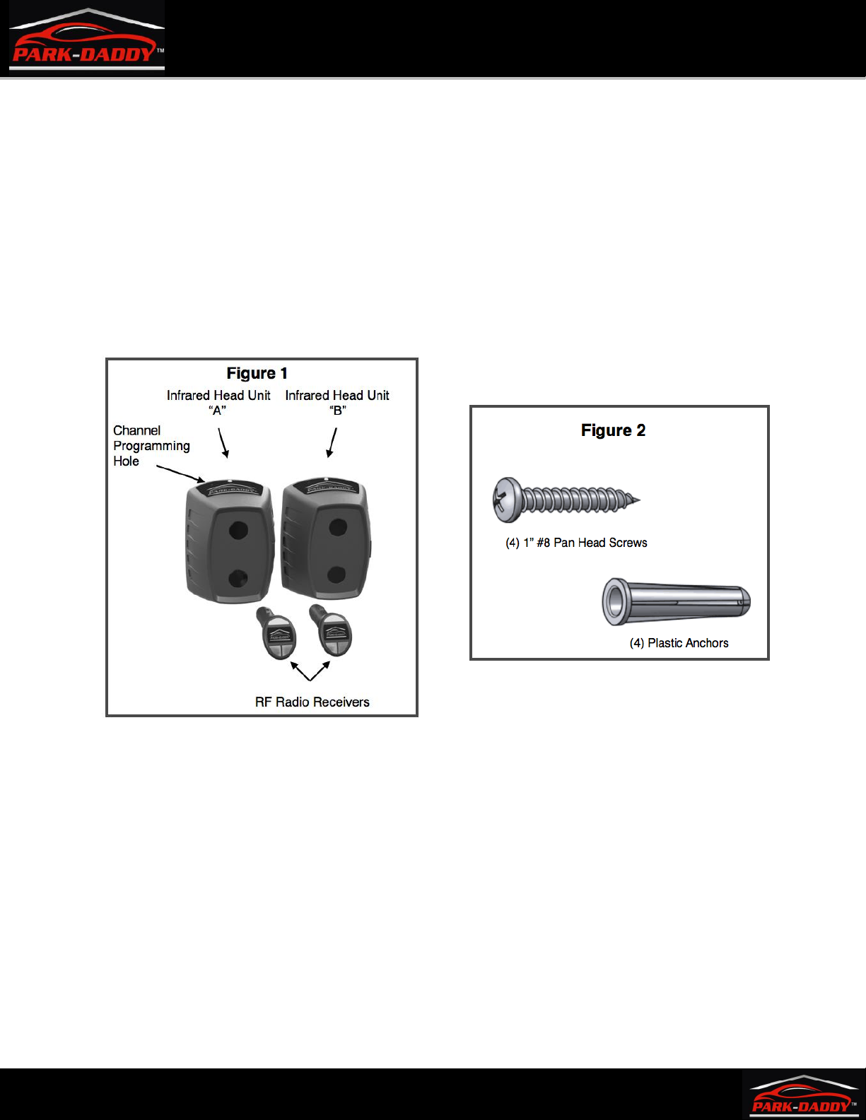
There are 2 Infrared Head Units with this system, “A” and “B”. Infrared Head Unit “A” is marked
with the letter “A” on the bottom label and has a small Channel Programming Hole to the left of
the LED on the top of the head unit. Infrared Head Unit “B” is marked with the letter “B” on the
bottom label and has only a LED on the top of the head unit. It does not matter which Infrared
Head Unit is mounted to each mounting wall. (See Figure 1)
The Park-Daddy® Vehicle Parking System is designed to be mounted in the garage to notify the
operator of a vehicle when the rear bumper has cleared the garage door opening and it will be
safe to close the garage door, leaving the maximum amount of room in the front of the vehicle.
The Park-Daddy® Vehicle Parking System can be used in garages with up to 4 parking spots
across.
The Park-Daddy® can also be used as an invisible barrier in the front and the side of the vehicle
to warn you when a vehicle is close to objects placed in the garage. For installation instructions
for the other alternative uses, please refer to the Alternative Uses section.
INSTALLING BATTERIES
Each Infrared Head Unit requires (2) D size alkaline batteries to be installed. (Batteries not
included.)
1. Remove battery door by pulling down the tab on top of the battery door and pulling the
top of the door outward.
2. Hold the Infrared Head Unit in one hand with the opening upward and the top of the
Head Unit facing away (The top of the Head Unit has the product label and the LED).
3. Install the first battery with the (+) positive terminal touching the contact in the top end
on the battery compartment.
4. While holding the first battery in place with your thumb, place the (-) negative terminal
of the second battery on the spring in the lower section of the battery compartment and
compress the spring until there is enough clearance for the second battery’s (+) positive
terminal to make contact with the first battery’s (-) negative terminal.
5. Replace the battery door with the tab on the bottom of the door inside the battery
compartment first then pull down the locking tab on the top of the door and push the
battery door inward until the door completely closes.
6. Repeat the above procedure on the remaining Infrared Head Unit.
The Red LED on Infrared Head Unit “A” will illuminate and the LED on Infrared Head Unit “B”
will flash Green every 15 seconds after batteries are installed until both Infrared Head Units
are paired.

DETERMINING VEHICLE CLEARENCE
Locate Mounting Template at the end of this User Manual.
The distance from the inner part of the garage door and line “B” of the
Mounting Template can be determined by the following:
1. With the garage door in the closed position, determine the inner most point of the
interior section of the garage door including handles, hinges, supports, hurricane struts
or trusses and any other protrusion attached to the interior of the door.
2. Using a pencil, erasable marker or a piece of tape, mark the floor of the garage at each
end of the garage door twice approximately 6 inches apart at the inner most point of
the interior section of the garage door. Run a straight edge from both marks to the
mounting walls and place a mark on the bottom of each mounting wall.
3. By marking the mounting walls as determined in the previous paragraph, you can now
find a safe clearance. From that mark, you will add different variables such as roll back
allowance after putting your car in the park position and releasing the brake and other
variables like bumper moldings and trim and/or trailer hitches and trailer hitch
receivers. Always add an additional 1 inch safety margin. Example: 1 inch safety margin
+ 3 inches for roll back + 1 inch for bumper trim = 5 inches clearance.
4. From the marks, you made on the mounting walls add the clearance measurement and
mark the mounting walls again extending the mark away from the garage door. You now
have determined the measurement that will be the placement of line “B” on the
Mounting Template. (See Figure 3)
This manual suits for next models
1
Table of contents
Popular Automobile Accessories manuals by other brands

ULTIMATE SPEED
ULTIMATE SPEED 279746 Assembly and Safety Advice

SSV Works
SSV Works DF-F65 manual

ULTIMATE SPEED
ULTIMATE SPEED CARBON Assembly and Safety Advice

Witter
Witter F174 Fitting instructions

WeatherTech
WeatherTech No-Drill installation instructions

TAUBENREUTHER
TAUBENREUTHER 1-336050 Installation instruction