Bulletin TI-NITROFLOW60-G Installation, Operation and Maintenance Manual
NitroFlow60 and NitroFlow60D Generators
www.labgasgenerators.com
4
1-800-343-4048
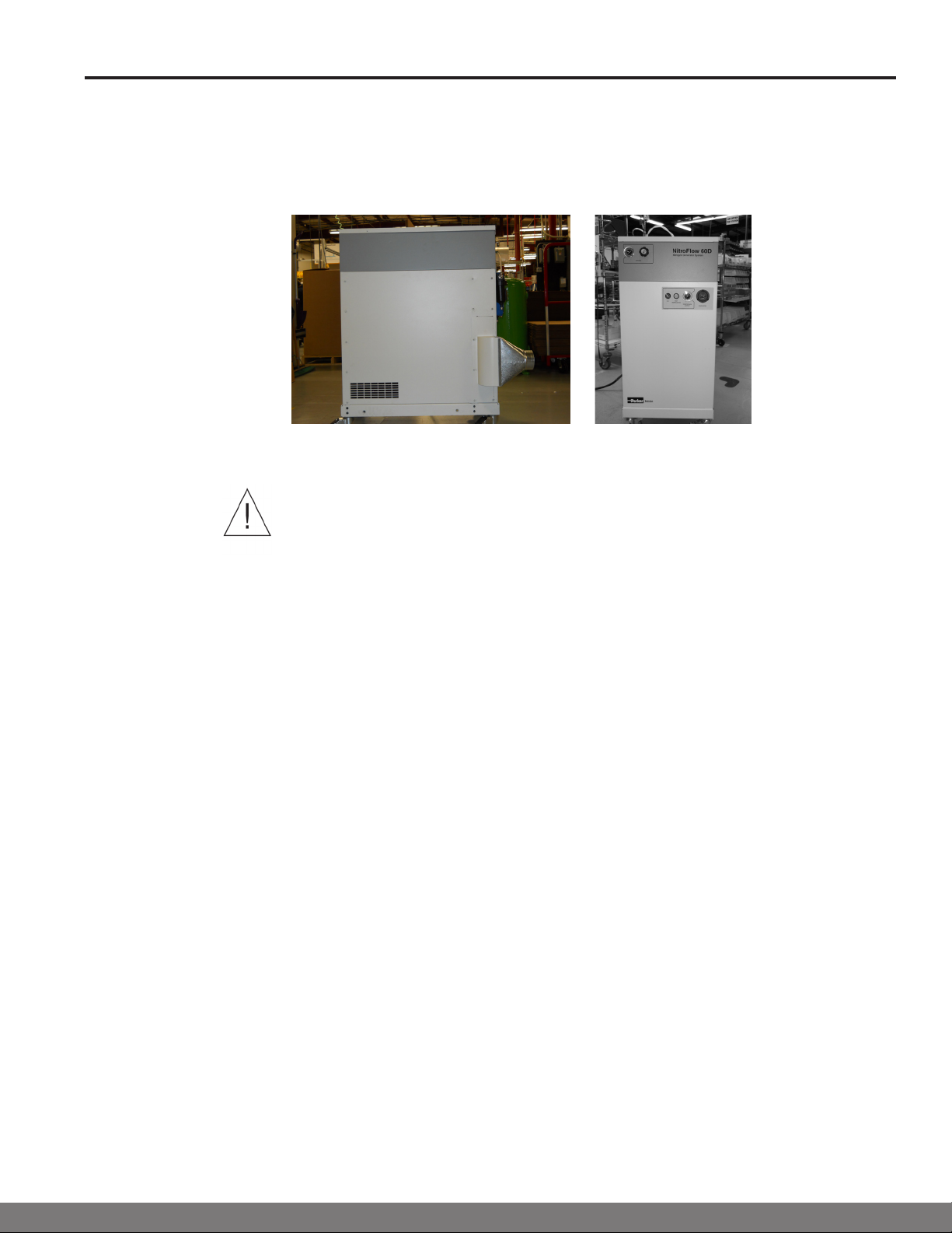
The NitroFlow60 Nitrogen Generator System Series are available in two models (Figure 1):
(1) NitroFlow60 Nitrogen Generator System(No Dry Air output)
(2) NitroFlow60D Nitrogen Generator System(Dry Air output)
The integrated system is engineered to produce pure nitrogen gas and clean, dry -40°F dew point
air gas from compressed air delivered by a carefully matched scroll compressor. The system is
housed in two fully integrated cabinets: the lower cabinet produces the compressed air using an
oil-less rotary scroll compressor. The upper cabinet removes contaminants and separates the
compressed air into the two gases.
General Description
The generator is certied to the electrical safety requirements as specied by the IEC, UL,
and CSA standards. These units bear the CSA marking on the product. Product supplied
internationally also carries the CE mark. The product meets EMC compliance. Internal pressure
receivers are CRN and ASTM certied or CE certied.
Regulatory
Compliance
The NitroFlow60 generator contains the necessary components to produce reliable, oil-free
compressed air, pure nitrogen, and dry air gases. The system consists of ve functional
technologies: (1) compressed air, (2) liquid water removal, (3) preltration, (4) oxygen/carbon
dioxide/water vapor removal, and (5) nal ltration. The nitrogen generator ow schematic (gure
2) shows the airow through the intake lter, compressor pump, aftercooler, receiver tank, and
check valve. The compressed air then ows through a water separator and preltration where
additional water (liquid and vapor) is removed. After ltration, the compressed air ow passes
through a 3-way pneumatic valve, an activated carbon prelter, nitrogen module, pressure
regulator, and post carbon lter, providing the nitrogen gas. The second ow path passes through
a back pressure regulator to maintain a 100% duty cycle of the compressor. The third ow path
passes through a dryer membrane providing dry air. Dry air available on NitroFlow60D series only.
Integrated System
The oil-less rotary scroll compressor is based on the theory of scroll compression. It offers high
reliability and quiet operation. The scroll set consists of two identical spirals; offset 180° with
respect to the other so the scrolls mesh. One scroll is orbited around the xed scroll, trapping and
compressing gas pockets as the pockets move to the center of the xed scroll. The compressed
gas is discharged from the pump through the center outlet.
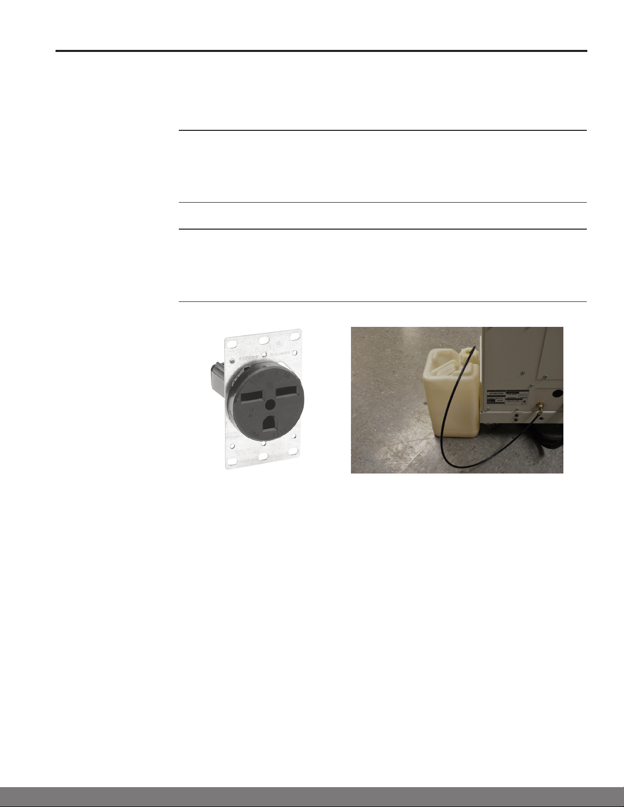
The air-cooled aftercooler on the scroll compressor is a series of cooling ns and a high output
fan. The cooling features allow the scroll compressor to operate at lower temperatures and
extend bearing, tip seal and grease life. The aftercooler cools the temperature of the discharge
air. The temperature of the discharge air is lowered, producing trapped water in the tank. The
water is then discharged through the automatic electric drain valve and collected in a disposal
container.
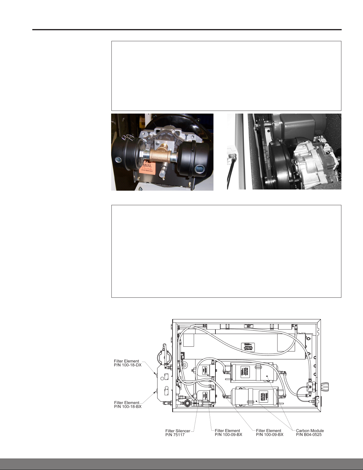
Compressor Pump
Compressor
After Cooler
Figure 2, Nitrogen Generator Flow for NitroFlow60 and NitroFlow60D