Parker Zander BSP-MT 10/D3 User manual

BSP-MT 10-95/D3
Dryer for Breathing air system
Operating manual
28/01/2020 - rev01 EN
Cod: 398H271981
( Generation - 3)


EN | User Manual
BSP-MT 10-95/D3 1
Index
Machine passport 3
General information 4
Manufacturer’s details .............................................................................................................. 4
Details on the dryer................................................................................................................... 4
About these operating instructions........................................................................................... 5
For your own safety 6
General safety notes................................................................................................................. 6
Intended use of the dryer.......................................................................................................... 7
Signs, instruction plates and danger zones at the dryer........................................................... 8
Transportation, installation and storage 10
Information on transportation packaging................................................................................ 10
What to do in the case of transport damage occurring? ........................................................ 10
Transporting and installing the dryer....................................................................................... 11
Storing the dryer ..................................................................................................................... 13
Technical product description 14
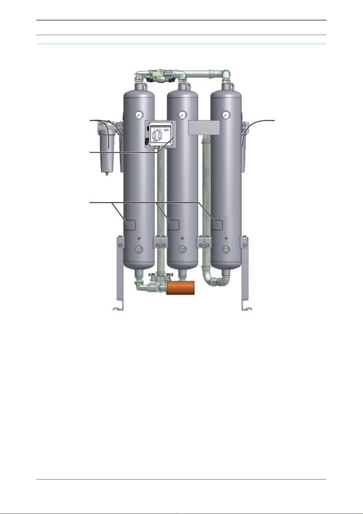
Summary Drawing Standard Dryer*........................................................................................ 14
Function description ............................................................................................................... 14
Available options..................................................................................................................... 17
Installation 18
Preconditions for installation .................................................................................................. 18
Connect piping ....................................................................................................................... 19
Installing the electrical connection.......................................................................................... 20
Start-up 22
Requirements for initial start-up ............................................................................................. 22
Setting times of the operating phases .................................................................................... 23
Overview of operating and control elements .......................................................................... 23
Start up dryer.......................................................................................................................... 26
Changing cycle mode (optional) ............................................................................................. 28
Monitoring dryer operation 29
With dewpoint-sensing control (optional) ............................................................................... 29
Shutdown and restart dryer 30
Emergency shutdown ............................................................................................................30
Depressurising and shutting down the dryer .......................................................................... 30
If work is to be carried out on the electrical system ............................................................... 31
Restart .................................................................................................................................... 31
Maintenance and repair of the dryer 33
Notes on maintenance............................................................................................................ 33
Regular maintenance intervals................................................................................................ 34
Instructions for use of the dongle ........................................................................................... 35
Daily maintenance tasks ......................................................................................................... 36
Maintenance work to be completed every 12 months............................................................ 37
Notes on further maintenance work........................................................................................ 39
Identify and eliminate faults 40
Summary of faults................................................................................................................... 40
Annex with technical documentation 44

EN | User Manual
2 BSP-MT 10-95/D3
Technical data......................................................................................................................... 45
Replacement and wear part list .............................................................................................. 47
Tightening torque values......................................................................................................... 49
Logic control diagram............................................................................................................. 50
Flow diagram .......................................................................................................................... 52
Dimensional drawing .............................................................................................................. 53

EN | User Manual Machine passport
BSP-MT 10-95/D3 3
Machine passport
It is the responsibility of the owner,
◊ to enter for the rst time any appliance data not stated above,
◊ to keep these appliance data up to date.
The above-stated appliance data provide for a clear identication of the dryer and its compo-
nents, and signicantly facilitate any service measures.
Further important data on the dryer such as the details on the permissible operating pressure
and the electrical connection are found on the type plate (for position of the type plate see
page 8 )

EN | User Manual General information
4 BSP-MT 10-95/D3
General information
Manufacturer’s details
Name and address
Parker Hannifin Manufacturing S.r.l.
Sede Legale: Via Privata Archimede, 1- 2009 Corsico (MI) Italy
Sede Operativa: Gas Separation and Filtration Division EMEA - Strada Zona Industriale, 4
35020 S.Angelo di Piove (PD) Italy
tel +39 049 971 2111- fax +39 049 9701911
Web-site: www. parker.com/hzd
e-mail: technical.support.hiross@parker.com
Details on the dryer
Standard equipment
Standard dryer*, consisting of
◊ 1 double-chamber hollow section vessel, llied with drying agent
◊ 1 single-chamber hollow section vessel, lled with purifying agent
◊ 2 upstream lter
◊ 1 downstream lter
◊ Mufer
◊ Control system
Associated documents
◊ Operating instructions (present)
◊ Technical documentation (see annex)
◊ Circuit diagrams (see separate document)
◊ Operating manual for installed lters (separate document)
Notes on supplementary documents
Supplementary documents such as operating manuals for options or pertaining components
must always be heeded. They contain additional information, e.g. regarding maintenance,
and are therefore necessary for safe operation of the plant.
* Planned dryers may be equipped with special components

EN | User Manual General information
BSP-MT 10-95/D3 5
About these operating instructions
These operating instructions contain basic information on the safe use of the dryer.
Characters and symbols used
Work steps that you have to carry out in the sequence stated are marked by black tri-
angles.
◊ Lists are marked by a small box
Note:
These notes provide you with hints and information on the safe and efficient
handling of machines and devices.
Warning!
These safety notes warn against damage to property and help you to avoid
such damage.
Danger!
These danger notes with a grey background warn against personal injury and/
or danger to life and limb; danger notes help you to avoid serious or life-threa-
tening situations for yourself and/or third parties.
Target group of these operating instructions
These operating instructions are intended for all persons working on and using the dryer. We
assume that all such persons are specialist personnel according EN ISO 7396-1.
Operating instructions: handling
These operating instructions must be continuously available at the site where the adsorber is
used. We recommend to prepare a copy and to keep the same in a safe and freely accessible
place next to the adsorber. Keep the original document in a safe place.

EN | User Manual For your own safety
6 BSP-MT 10-95/D3
For your own safety
The dryer has been built in accordance with the state of the art and the recognized technical
safety regulations. Nevertheless, there is a risk of personal injury and damage to property
when the dryer is used, if
◊ it is operated by non-qualied personnel,
◊ not used within its intended design specications,
◊ is repaired or maintained incorrectly.
Note:
For your own safety and to prevent machine damage, please note the informa-
tion and safety notes in these operating instructions when working with the
dryer.
General safety notes
Warning against sudden air ejection
When the hollow section vessels are depressurised, air flows suddenly out of
the sound absorber.
◊ This causes a sudden loud cracking noise.
◊ Due to particles carried in the air flow, there is a very considerable risk of
eye injury.
When working on the dryer, always wear eye and ear protection equipment.
Hazard due to a sudden release of pressure!
Never remove any parts of the dryer, or manipulate the same in any way, for
as long as the plant is still pressurised! A sudden escape of pressure may
cause serious injuries.
Before carrying out any work on the dryer, first depressurise the plant.
Risk of injury due to voltage-carrying parts!
The electrical supply cable and external power lines are live even after the
dryer is switched off and, in the event of body contact, may cause serious
injury! Before carrying out any work on the electrical system, the electrical
supply cable and all external power lines must be made voltage-free!
Personnel qualification
Only authorized and qualied specialist personnel may be tasked with the work on the dryer
described in these operating instructions.
Conversions and modifications
Without prior approval by the manufacturer, no conversions and modications must be made
to the dryer! Any non-approved modications may restrict the operational safety of the dryer
and cause damage to property or personal injury.
Handling drying agents
The drying agents used do not pose any risk to health. However, when lling and emptying
the hollow section vessels with drying agents, increased dust generation may occur. Please
comply with the following instructions:
◊ When lling drying agents, wear a dust mask and eye protection!
◊ If a spillage occurs, any spilt drying agent must be taken up immediately. There is a risk of
skidding!

EN | User Manual For your own safety
BSP-MT 10-95/D3 7
Disassembly and disposal
◊ Dispose all parts of the dryer, the drying agent, and all other operating materials in an envi-
ronmentally safe way and in accordance with all current statutory regulations.
Intended use of the dryer
The dryer is exclusively intended for drying compressed air. Depending on dened input
conditions, it dries compressed air for industrial use.
The dryer is designed for compressed air, which is free from aggressive water, oil, and solid
matter constituents.
As standard, the dryer is intended to be sited within a building and protected against the
weather.
The dryer may be operated only in accordance with the data on the type plate and in accord-
ance with the contractual conditions.
Suspected misuse
The dryer must not be misused as a climbing aid! Pipes, valves, and similar ttings have not
been designed for such loads. They could fracture, tear off, or become damaged in another
way.

EN | User Manual For your own safety
8 BSP-MT 10-95/D3
Signs, instruction plates and danger zones at the dryer
Signs and instructions
Front view
Please note the above plates and instructions attached to the dryer. Ensure that they are not
removed and are always readable.
Type plate of
the upstream
lter
Type plate of
the dryer
Vessel plate
Type plate of
the down-
stream lter

EN | User Manual For your own safety
BSP-MT 10-95/D3 9
Hazard areas on the dryer
Symbol Hazard area
Warning against hazardous electrical voltage
Different parts of the dryer carry electrical current. These parts may be connected,
opened, and maintained by authorized specialist personnel only.
Warning against overpressure
The entire dryer is under pressure. Before commencing any work, the plant must
be depressurised.
Warning against sudden air ejection
When the vessels are depressurised, air ows suddenly out of the sound absorber:
◊ This causes a sudden loud cracking noise.
◊ Due to particles carried in the air ow, there is a very considerable risk of eye
injury.
When working on the dryer, always wear eye and ear protection equipment.
Skid risk
When emptying and lling the vessels with drying agent, there is a risk of skidding
caused by spilt drying agent.
Hazard caused by overpressure
Hazard caused by electrical voltage
Hazard caused by sudden air ejection
during expansion
Risk of damage to eyes

EN | User Manual Transportation, installation and storage
10 BSP-MT 10-95/D3
Transportation, installation and storage
Danger due to incorrect transportation!
The dryer must be transported by authorized and qualified specialist personnel
only. During transportation all applicable national regulations for accident pre-
vention must be complied with. Otherwise there is a risk of personal injury.
Always adhere to the stickers and notes on the packaging of the dryer!
◊ Only use suitable and technically perfect lifting gear with a sufcient carrying capacity.
During transportation the dryer must be carefully secured against falling over.
The manufacturer will not be liable for any damage caused by incorrect storage or incorrect
transportation. Please note therefore the following instructions as well as the storage instruc-
tions on page 13.
Information on transportation packaging
Depending on the type of transportation, the dryer is delivered in different types of packag-
ing:
◊ All transportation types: the apertures of the dryer are closed off by means of plugs.
◊ In addition, when transportation is effected by air: the dryer is packaged in a wooden box.
◊ In addition, when transportation is effected by ship: the dryer is packaged in a lm material
and in a wooden box.
If the packaging is undamaged
The undamaged packaging should be removed only at the nal installation site, as it
offers protection against any weather inuences.
What to do in the case of transport damage occurring?
Check whether only the packaging or the dryer itself were damaged.
Inform the haulier immediately in writing of any damages.
Contact the manufacturer urgently in order to report the damage.
Warning!
A damaged dryer must not be taken into operation! Damaged components may
lead to functional faults and possibly cause further damage.

EN | User Manual Transportation, installation and storage
BSP-MT 10-95/D3 11
Transporting and installing the dryer
Requirements for the installation site
The conditions at the installation site have a large inuence on the functional capability of the
dryer and the service life of the drying agent. In order to ensure a mode of operation, which is
as continuous as possible, and low maintenance, the installation site must meet the following
requirements:
◊ The installation site must be located within a building. Protect the dryer against moisture.
◊ The ambient temperature must not drop below +1,5 °C (34,7 °F).
◊ Heed the dryer’s noise emission when selecting the installation location.
◊ The installation area must be level, rm and vibration-proof. It must have the necessary car-
rying capacity for the weight of the dryer. The weight of the dryer is specied in the technical
data section of the annex.
◊ The dryer should be installed with sufcient
spacing at the top, sides, and rear, in order to
be able to carry out maintenance work and
change the drying agent without any hindranc-
es (see gure).
If in doubt, the installation site must be inspect-
ed by specialists. If you have any queries in this
regard, please contact the manufacturer (see
pag. 4
Necessary spacing at the top and sides
= min. 1 m
Transportation using lifting or forklift trucksr
Warning against damage to property!
The dryer is delivered standing on its side on a transportation pallet. Top and
sides have not been designed for mechanical loads. Therefore do not place any
load onto the top face. Do not stack.
Therefore, always transport the dryer on a lifting or forklift truck.
The dryer should only be transported in an upright position.
Secure the dryer on the lifting or forklift truck against sliding movements.
Transport the dryer to its installation site.

EN | User Manual Transportation, installation and storage
12 BSP-MT 10-95/D3
Installing the dryer
Caution!
Always use the lifting lugs at the top of the tank to lift the dryer. Use a lifting
beam with a suitable spacing for this purpose. This will ensure the tanks can-
not come in contact with the upper pipe bridge and thus damage it.
Remove the packaging of the dryer.
Attach suitable lifting gear to the transport lugs of the vessels (see gure I).
Raise the dryer (see gure II) and remove the transportation pallet.
Place the dryer at its installation site.
I: Transport lugs on pressure vessel II: Installing by crane
Anchoring the dryer
Use suitable attachment material to anchor the dryer to the oor.
In the case of vibrating oors: place the dryer on suitable vibration dampers.

EN | User Manual Transportation, installation and storage
BSP-MT 10-95/D3 13
Storing the dryer
If the dryer is to be stored for an extended period of time, the storage location must meet the
following conditions:
◊ The dryer must not be stored in the open air.
◊ The storage room must be dry.
◊ The storage room must be free from dust or the dryer must be covered by a protective
sheet.
◊ The storage room must have an ambient temperature of at least +1 °C (33,8 °F).
In order to store the dryer proceed as follows:
Take dryer out of operation as described on page 30.
Ensure that the compressed air inlet valve installed by the owner, and the installed
compressed air outlet valve installed by the owner, are both closed, and that the dryer is
depressurised.
Disconnect dryer from the compressed air system.
Disconnect the dryer from the electrical power supply and all external lines.
Use lm material or similar to close the compressed air inlet apertures and compressed
air outlet apertures on the dryer in order to protect them against contamination.
If possible cover dryer with a protective sheet.
The dryer can now be stored for long periods.
Note:
If you wish to take the dryer back into service after an extended period of sto-
rage, please proceed as described for its first commissioning and start-up (see
page 26).
Store drying and purifying agents
Do not store drying agents in the open air.
Protect drying and purifying agents against humidity.

EN | User Manual Technical product description
14 BSP-MT 10-95/D3
Technical product description
Summary Drawing Standard Dryer*
Function description
The dryer dries and puries the compressed air supplied by the compressor and provides
medical breathing air.
The air is thereby dried alternately in one of the drying agent vessels. The dried air is subse-
quently puried in the third vessel, whereby oil residue and other contaminants are removed.
Before the compressed air is fed into the dryer, it ows through upstream lters where dust,
dirt, oil and water droplets are removed. Thus, the installed upstream lter is also used for
extending the service life of the drying agent.
The installed downstream lters clean the compressed air from drying agent abrasions, be-
fore it is fed into the compressed air system.
The two vessels contain an extremely porous drying agent by means of which humidity is
removed from the compressed air and stored just as in a sponge. The stored humidity is then
removed again from the drying agent and re-introduced into the ambient environment.
To this end, the two vessels alternate between different operating modes. Whilst in one ves-
sel, compressed air is de-humidied (adsorption), in the other vessel the humid drying agent
is prepared for another charge (regeneration). These two states, which run in parallel during
compressed air preparation, are described below.
Check valve block
Compressed air outlet
On/Off-Switch
Compressed air inlet
Upstream lter
Power supply connector
Downstream lter
Control cabinet
Mufer
Discharge point
Vessel
Vessel pressure gauge
Pressure dew point Transport lugs
Solenoid valve block

EN | User Manual Technical product description
BSP-MT 10-95/D3 15
Adsorption
Via a compressor, humid compressed air is
supplied to the upstream lter. From here, the
compressed air ows upwards through the
absorption vessel, which is pressurised. In so
doing, the drying agent dehumidies the air.
The dried compressed air is supplied to the
pipe network via the purifying vessel and the
downstream lter.
Here, adsorption is shown in the left
vessel.
Regeneration (running in parallel to the adsorption)
At the same time the other chamber is prepared for a renewed take-up of humidity. This
process is called regeneration.
The regeneration is subdivided into three phases: expansion, dehumidication, and pres-
sure build-up.
With the dewpoint-sensing control option, the regeneration phase is followed by a standby
phase.
Expansion phase
During the expansion phase the pressure in the
right chamber is released via the mufer down
to ambient pressure within just a few seconds.
The outow of the compressed air becomes
noticeable due to a sudden powerful ow noise
at the mufer.
Dehumidification phase
Prior to being released into the pipe network,
dried compressed air is bled by means of an
orice plate. This separate regeneration air ow
is fed through the depressurised chamber. The
humidity stored in the drying agent is taken up
by the air ow and expelled into atmosphere via
the mufer.
Here, regeneration is shown in the right
vessel.

EN | User Manual Technical product description
16 BSP-MT 10-95/D3
Pressure build-up phase
After dehumidication the pressure in the
regenerated hollow section vessel is built up to
operating pressure, so that the switchover from
regeneration to adsorption can take place at
operating pressure level.
Pressure build-up
Standby phase (only with the dewpoint-sensing control option)
When in standby phase, the fully regenerated vessel is ready for absorption operation. The
system is switched to this vessel, as soon as the measured dewpoint at the compressed air
outlet has reached the set dewpoint value for switchover.
Switchover
When the drying agent in the adsorbing chamber has taken up a sufcient level of humidity,
then the switchover between the vessels will be effected between the vessels. Following
switchover, the above-described process is repeated, with the adsorption and regeneration
now taking place in the respective different vessel.

EN | User Manual Technical product description
BSP-MT 10-95/D3 17
Available options
The following options are available for the dryer:
◊ Start-up device
◊ Signalling contacts of control system and compressor synchronisation
◊ Dewpoint-sensing control
◊ Fine lter mufer
◊ Nozzle kit
Start-up device
A start-up device basically consists of a pressure holding device, which is located at the rear
of the dryer. The pressure holding device ensures that pressure can build up in the dryer and
adsorption take place.
It is always required when an empty compressed air reservoir or an empty compressed air
system must be lled downstream of the dryer (e.g. following weekend shutdowns and when
the pressure in the compressed air system can frequently drop below the stated operating
pressure).
Signalling contacts of the control system & compressor synchronisation
The control system is equipped with a digital input for the synchronised operation with a
compressor. This feature allows for synchronised and thus efcient dryer operation with
discontinuous compressor operation.
Compressor synchronisation helps reduce energy costs, as the dryer can be operated inde-
pendently of the compressor.
The compressor synchronisation controller is a higher-level controller than the pressure dew
point controller (see below). When both options are in place, the compressor synchronisation
controller is treated as the prime controller.
The control system can also be equipped with an optional operation signalling contact with
which the dryer operation can be monitored from an external device. Dryers with the optional
dewpoint-sensing control are equipped with such a contact as standard. It is used for the
transmission of operating signals and for the output of dewpoint alarms.
Dewpoint-sensing control
With a dewpoint-sensing control system, you can operate the dryer in xed or variable
cycles. In the xed cycle, switchover is effected after a xed time period (usually after 5
minutes). In the variable cycle, the switchover is effected in relation to the dew point reached
and the charging of the drying agent . The adsorption time in the variable cycle amounts to
60 minutes maximum.
Fine filter muffler
A ne lter mufer is used to reduce the noise emission of the dryer to lower levels than the
standard mufer can provide. If installed, the ne lter mufer replaces the original installed
mufer.
Nozzle kit
In the case that the operating pressure deviates from the standard design pressure (7bare)
it is possible that the amount of necessary regeneration air changes. This effect may have
a negative impact on the cost-effectiveness of the dryer. To prevent this, it is possible to
replace the built in regeneration air nozzle by a nozzle with a modied bore. This replacement
optimizes the regeneration air consumption and therefore restores the energy efciency of
the dryer. To receive more information on this conversion, please contact the manufacturer.

EN | User Manual Installation
18 BSP-MT 10-95/D3
Installation
Only authorized and qualified specialist personnel may carry out work on pipes
and electrical systems.
As soon as the dryer has been set up at its installation location, you can install the com-
pressed air infeed and outlet lines make the electrical connections.
Preconditions for installation
For a correct installation the following preconditions must be met on the part of the owner.
◊ Connections and lines for the infeed and outfeed of compressed air must be provided.
◊ A compressed air inlet valve as well as a compressed air outlet valve must be installed by
the owner, so that the dryer can be installed and maintained in a depressurised condition
(see also the installation example on page 19).
◊ All pipes, couplings, and connections must have the correct diameter and match the oper-
ating pressure.
Hazard caused by exceeding the limit values!
A safety device must be provided in order to protect against the maximum
permissible operating pressure from being exceeded.
The safety device must be installed so that the dryer is reliably protected from
exceeding the maximum permitted operating pressure even when the tempera-
ture of the compressed gas increases.
The data required to meet these preconditions are contained in the technical documentation
attached in the annex.
Warning!
If the above preconditions are not complied with, a safe operation of the dryer
cannot be assured. Also, the functionality of the dryer may be detrimentally
affected.
This manual suits for next models
8
Table of contents