Parker PVSG User manual

PVSG User Guide
Parker Vehicle System Gateway
Effective: June 2019
Supersedes: UG-PVSG-1051000-201906-003

PVSG User Guide
II
Parker Hannin Canada
Electronic Controls Division
1305 Clarence Avenue
Winnipeg, MB R3T 1T4 Canada
ofce +1 204 452 6776
Fax +1 204 478 1749
http://www.parker.com/ecd
Copyright 2019 © Parker Hannifin Corporation. All rights reserved. No part of this work may be reproduced, published,
or distributed in any form or by any means (electronically, mechanically, photocopying, recording, or otherwise), or stored in
a database retrieval system, without the prior written permission of Parker Hannin Corporation in each instance.
Warning!
FAILURE OR IMPROPER SELECTION OR IMPROPER USE OF THE PRODUCTS AND/OR SYSTEMS DESCRIBED
HEREIN OR RELATED ITEMS CAN CAUSE DEATH, PERSONAL INJURY AND PROPERTY DAMAGE.
• is document and other information from Parker Hannin Corporation, its subsidiaries and
authorized distributors provide product and/or system options for further investigation by users
having technical expertise.
• e user, through its own analysis and testing, is solely responsible for making the nal selection
of the system and components and assuring that all performance, endurance, maintenance,
safety and warning requirements of the application are met. e user must analyze all aspects
of the application, follow applicable industry standards, and follow the information concerning
the product in the current product catalog and in any other materials provided from Parker or its
subsidiaries or authorized distributors.
• To the extent that Parker or its subsidiaries or authorized distributors provide component or
system options based upon data or specications provided by the user, the user is responsible for
determining that such data and specications are suitable and sucient for all applications and
reasonably foreseeable uses of the components or systems.
• e user will be solely responsible for nal disposal of all products.

PVSG User Guide
III
Contents
Publication History ...........................................................................................................................V
Safety ......................................................................................................................................... VI
Safety symbols .......................................................................................................................................VI
General safety regulations ....................................................................................................................VI
Welding after installation .................................................................................................................... VII
Construction regulations .................................................................................................................... VII
Safety during installation .................................................................................................................... VII
Safety during start-up .......................................................................................................................... VII
Safety during maintenance and fault diagnosis ................................................................................ VII
1. About the PVSG ................................................................................................................ 1
2. Connectors and pin-outs ................................................................................................. 3
3. Inputs ................................................................................................................................6
3.1. Input capabilities ......................................................................................................................6
3.1.1. Power control digital input connections ................................................................................7
3.1.2. Active-high digital input connections ....................................................................................7
4. Outputs ............................................................................................................................. 9
4.1. Output capabilities ...................................................................................................................9
4.2. High-side output connection ..................................................................................................9
5. Power .............................................................................................................................. 11
6. Communication ............................................................................................................. 12
6.1. Controller area network .........................................................................................................12
6.1.1. CAN Capabilities ....................................................................................................................12
6.1.2. J1939 CAN Installation Connections ....................................................................................12
6.2. Wi-Fi ........................................................................................................................................14
6.2.1. Compliance with FCC/IC (wireless) .....................................................................................14
6.3. USB ..........................................................................................................................................14
6.4. SAE J1708.................................................................................................................................15
6.5. Local Interconnect Network ..................................................................................................15
6.6. Ethernet ...................................................................................................................................15
7. Installation ..................................................................................................................... 17
7.1. Mounting the PVSG to a Vehicle ...........................................................................................17
7.2. Mechanical Requirements .....................................................................................................17
7.3. Dimensions .............................................................................................................................18

PVSG User Guide
IV

PVSG User Guide
V
Publication History
e following table provides an overview of the changes made to this document over the course of its
publication history.
Release Date Description of Change
Rev. 001 First release of this document
Rev. 002 Realignment to match platform changes. Minor edits
throughout. 01/07/2019
Rev. 003 Add note for USB no communication, 6/12/2019

PVSG User Guide
VI
Safety
Do not perform the procedures in this manual unless you are experienced in the handling of electronic
equipment.
Contact the manufacturer if there is anything you are not sure about or if you have any questions
regarding the product and its handling or maintenance.
e term “manufacturer” refers to Parker Hannin Corporation.
Safety symbols
e following symbols are used in this document to indicate potentially hazardous situations:
Danger! Risk of death or injury.
Warning! Risk of damage to equipment or degradation of signal
When you see these symbols, follow the instructions carefully and proceed with caution.
General safety regulations
Work on the hydraulics control electronics may only be carried out by trained personnel who are well-
acquainted with the control system, the machine, and its safety regulations.
Follow the manufacturer’s regulations when mounting, modifying, repairing, and
maintaining equipment. e manufacturer assumes no responsibility for any accidents
caused by incorrectly mounted or incorrectly maintained equipment. e manufacturer
assumes no responsibility for the system being incorrectly applied, or the system being
programmed in a manner that jeopardizes safety.
Do not use the product if electronic modules, cabling, or connectors
are damaged or if the control system shows error functions.
Electronic control systems in an inappropriate installation and in combination with
strong electromagnetic interference elds can, in extreme cases, cause an unintentional
change of speed of the output function.

PVSG User Guide
VII
Welding after installation
Complete as much as possible of the welding work on the chassis before the installation of the system. If
welding has to be done afterwards, proceed as follows:
Do not place the welding unit cables near the electrical wires of the control system.
1. Disconnect the electrical connections between the system and external equipment.
2. Disconnect the negative cable from the battery.
3. Disconnect the positive cable from the battery.
4. Connect the welder’s ground wire as close as possible to the place of the welding.
Construction regulations
e vehicle must be equipped with an emergency stop which disconnects the supply voltage to the
control system’s electrical units. e emergency stop must be easily accessible to the operator. If
possible, the machine must be built so that the supply voltage to the control system’s electrical units is
disconnected when the operator leaves the operator’s station.
Safety during installation
Incorrectly positioned or mounted cabling can be inuenced by radio signals, which can
interfere with the functions of the system.
Safety during start-up
Danger! Risk of death or injury. Do not start the machine’s engine before the control
system is mounted and its electrical functions have been veried.
Do not start the machine if anyone is near the machine.
Safety during maintenance and fault diagnosis
Before performing any work on the hydraulics control electronics, ensure that
• e machine cannot start moving.
• Functions are positioned safely.
• e machine is turned o.
• e hydraulic system is relieved from any pressure.
• Supply voltage to the control electronics is disconnected.

PVSG User Guide
1
1. About the PVSG
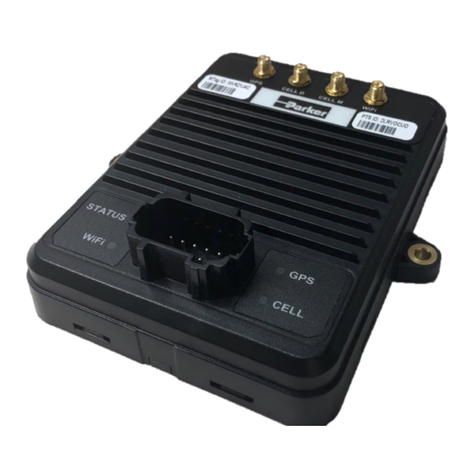
e PVSG (Parker Vehicle System Gateway) product is a gateway providing routing and gateway
interfacing between various communication ports. e hardware includes the following interfaces for
use in a system environment:
• 5x CAN (depending on version)
• 4x LIN (depending on version)
• 1x J1708 (depending on version)
• 1x USB (OTG)
• 1x Ethernet 100baseTx (depending on version)
• 1x 802.11 b,g,n
• 1x external wireless antenna (depending on version)
• 2x digital inputs (depending on version)
• 1x high-side output (depending on version)
Figure 1.1. PVSG module
e design of the gateway platform is structured to provide two levels of connectivity. Packages of
software capability supported by each version is included with the gateway. It is also possible to provide
customers with features that can be purchased and added at any time after the product has been
delivered, if the purchased hardware version can support it.
is manual describes the hardware components of the PVSG, but does not explain the conguration
tool software. For more information about software, refer to the appropriate software manual or contact
your Parker Vansco Account Representative.

PVSG User Guide
2
e dierent models of the PVSG and their features are listed in the following tables:
Basic
Characteristic Number Description
CAN bus ports 5 Supports CAN 2.0 for e.g. J1939, CANopen
WiFi 0 802.11 b,g,n
External antenna conn. 0 Antenna may be connected for additional range
Ethernet 0 100base Tx for wired PC connection
USB 1 USB Host/Device (OTG)
J1708 1 Legacy heavy-duty vehicle (truck and bus) protocol
LIN 0 For communication with automotive components
Data logging memory 0 Memory for logging events, CAN messages etc.
RTC 1 Real time clock
Inputs 2 Active-high GPIO with wake up capability
Outputs 1 High-side
Advanced
Characteristic Number Description
CAN bus ports 5 Supports CAN 2.0 for e.g. J1939, CANopen
WiFi 1 802.11 b,g,n
External antenna conn. 1 Antenna may be connected for additional range
Ethernet 1 100base Tx for wired PC connection
USB 1 USB Host/Device (OTG)
J1708 1 Legacy heavy-duty vehicle (truck and bus) protocol
LIN 4 For communication with automotive components
Data logging memory 4 GB Memory for logging events, CAN messages etc.
RTC 1 Real time clock
Inputs 2 Active-high GPIO with wake up capability
Outputs 1 High-side

PVSG User Guide
3
2. Connectors and pin-outs
e PVSG has 2 Molex MX150 connectors that are keyed to prevent improper connection.
e mating connector for the PVSG, J1 connector is a 20 position MX150 key B (gray), and the mating
connector for the PVSG, J2 connector is a 16 position MX150 key A (black).
Figure 2.1. Molex MX150 connector example
Mating connector part numbers
Connector Molex part no. with CPA
locking clip
Molex part no. without CPA
locking clip
J1 connector (gray),
20-pin, key option B
334722007 334722002
J2 connector (black),
20-pin, key option A
334721606 334721601
Contacts 330013004 (16-20 awg gold) 330013004 (16-20 awg gold)
e pins in the Molex MX150 connectors are used for power, input, output, CAN, LIN, and J1708
communication channels, depending on version.
e following tables shows the pin-outs for the MX150 connectors:
J1 Connector Pinout
Pin I/O Name Function
1INPUT2 Input2 (GPIO)
2INPUT1 Input1 (GPIO)
3CAN2_SHLD CAN2 Shield
4CAN2_L CAN2 Low
5CAN2_H CAN2 High
6CAN1_SHLD CAN1 Shield
7CAN1_L CAN1 Low
8CAN1_H CAN1 High
9GND GND (Negative battery)
10 +VBATT +VBATT (Positive battery)
11 CAN3_SHLD CAN3 Shield
12 CAN3_H CAN3 High
13 CAN3_L CAN3 Low

PVSG User Guide
4
J1 Connector Pinout
Pin I/O Name Function
14 CAN4_SHLD CAN4 Shield
15 CAN4_H CAN4 High
16 CAN4_L CAN4 Low
17 CAN5_SHLD CAN5 Shield
18 CAN5_H CAN5 High
19 CAN5_L CAN5 Low
20 GND GND (Negative battery)
J2 Connector Pinout
Pin I/O Name Function
1GND J1708A
2CAN_L J1708B
3GND GND (Negative battery)
4LIN2 LIN2
5GND GND (Negative battery)
6LIN1 LIN1
7NC Reserved
8OUTPUT1 Output1
9NC Reserved
10 GND GND (Negative battery)
11 LIN4 LIN4
12 NC Reserved
13 NC Reserved
14 NC Reserved
15 GND GND (Negative battery)
16 LIN3 LIN3
In addition, there is 1 x USB (M12 5 pin), and depending on conguration, 1x Ethernet (M12 4 pin) and 1
x SMA Wi-Fi antenna connector.
Figure 2.2. M12 connector example

PVSG User Guide
5
Mating connector part numbers
Connector Possible mating part number
J11 connector,
4-pin, code D
3M: 3N104-D000-S08 BF
J12 connector,
5-pin, code B
AMP: 4-2271112-1
e following tables shows the pin-outs for the M12 connectors:
J11 Connector Pinout
Pin I/O Name Function
1Ethernet_TX+ Ethernet Transmit+
2Ethernet_RX+ Ethernet Receive+
3Ethernet_TX- Ethernet Transmit-
4Ethernet_RX- Ethernet Receive-
J12 Connector Pinout
Pin I/O Name Function
1GND USB GND
2PWR USB PWR
3D+ USB D+
4D- USB D-
5USB_OTG USB OTG ID

PVSG User Guide
6
3. Inputs
e PVSG has 2 GPIO inputs.
• Both inputs are active high and able to be used as wake up (power control) inputs to activate the unit
or shut it down.
Damage to equipment! Do not connect inputs directly to unprotected inductive loads
such as solenoids or relay coils, as these can produce high voltage spikes that may
damage the CM0504. If an inductive load must be connected to an input, use a protective
diode or transorb.
3.1. Input capabilities
ere are 2 active high inputs (INPUT1 and INPUT2). is GPIO Type 1 input provides a xed input
detection threshold with xed pull down resistance.
e primary function of the inputs is to provide a wake on ignition feature as a digital input. e ‘Wake
Up’ functionality is software congurable.
A secondary function is to interface with switch sensors in an application.
e following table provides specications for the inputs:
GPIO input Type 1 characteristics
Item Min Nom Max Unit
Input voltage range (non-operational) 0 32 V
Over voltage 36 V
Pull-up resistance open
Input resistance w.r.t. ground 10.11 kΩ
Negative going threshold 3.375 3.67 Vt
Positive going threshold 3.65 3.931 V
Filtering - hardware time constant 28 us

PVSG User Guide
7
3.1.1. Power control digital input connections
When connecting power control (wake up) inputs, note that
• e power control digital input is usually connected to the vehicle ignition, but it can be connected
to any power source in a system.
• To protect the harness that connects the PVSG to the ignition, place a fuse of 200 mA or higher in the
circuit that feeds the PVSG.
• When battery power (VBATT) is connected, and the power control digital input is inactive, the PVSG
will go into sleep mode.
e following diagram shows a typical power control digital input connection:
Internal to product
Power Control Input
Power
Control
Pull-Down
Resistor
Battery
Application Switch
Figure 3.1. Power control digital input installation connections
3.1.2. Active-high digital input connections
A digital input is typically connected to a switch that is either open or closed.
• When an active-high switch is open, the pull-down resistor ensures that no voltage exists on the
input signal, which will be interpreted by the PVSG as inactive.
• When the switch is closed, the input is connected to battery voltage, which will be interpreted by the
PVSG as active.
For an input that is active-high
• It must be connected to battery power so that there is a battery connection when the state of the
input changes.
• e power provided to the digital switch connected to the input must be provided through a fuse in
the wire harness.

PVSG User Guide
8
e following diagram shows a typical active-high digital input connection:
Internal to product
Active High
Digital Input
Battery
Application Switch
Figure 3.2. Active-high digital input installation connections

PVSG User Guide
9
4. Outputs
e PVSG provides a switched battery (open source) digital output (OUTPUT1). is output includes
hardware short circuit protection if a short circuit fault is detected.
4.1. Output capabilities
e following table provides specications for the high-side outputs:
Item MIN NOM MAX UNIT
Maximum output current 0 32 V
Output load current range 0 250 mA
Short circuit current limit
Output Resistance - w.r.t. ground: Output off 9.86
Output Resistance - w.r.t. VBATT: Output on 1 3
Output leakage current: Output off 20 uA
Output current, fault detection (Output off state) 4.5 mA
Output PWM frequency 20 Hz
Output duty cycle 50 %
Turn on delay, Off to On 500 us
Turn off delay, On to Off 500 us
Turn on/off slew rate 0.7 V/us
Output pin capacitance 10 nF
4.2. High-side output connection
When connecting the high-side output, note that
• High-side output circuitry is connected internally to battery power (VBATT).
• High-side output can provide switched battery power to any load type in a vehicle.
• High-side output can source up to 0.25 A max.
• High-side output have internal yback diodes, which are needed when driving inductive loads (the
yback diodes absorb electrical energy when the load is turned o).
Inductive loads will create an average current ow that moves out of the high-side output. When the
output is on, the current ows through the output driver, and when the output is o, the current ows
through the yback diode. A duty cycle of 50% will produce the worst case average current ow through
these two devices.
Note: If large inductive loads are used, and the high-side output is providing a continuous PWM signal,
the PWM peak current must not be greater than the specied continuous current for the output (in
continuous mode, the average current ow through the diode at 50% duty cycle is approximately equal to
½ the peak current).
When connecting high-side outputs, ensure you follow these best practices:
• High-side outputs should not be connected to loads that will draw currents greater than the
maximum peak current, or maximum continuous current.
• e grounds for the loads should be connected physically close to the PVSG power grounds.

PVSG User Guide
10
e following shows a typical high-side output connection:
Internal to product
High-Side
Output
Application
Load
Figure 4.1. High-side output installation connections

PVSG User Guide
11
5. Power
e PVSG is powered by a direct battery connection. e gateway is turned on by applying power to a
power control input or a CAN message depending on conguration.
e PVSG in a 12 V or 24 V system and can operate from 6.5 V up to 32 V with over-voltage protection at
36 V.
e following table provides specications for the PVSG power:
Item Min Nom Max Unit
Input voltage for normal operation 6.5 - 32 V
Maximum continuous voltage - - 36 V
Maximum peak current A
Current draw in sleep mode 285 uA
Recommended External Fuse - - 10 A

PVSG User Guide
12
6. Communication
e types of communication available to the PVSG family are Controller Area Network (CAN), Wi-Fi, USB
host/device, J1708, LIN, and Ethernet. e types and quantity of communication ports are dependent on
product version.
6.1. Controller area network
e PVSG has 5 Controller Area Network (CAN) communication port(s) available. e PVSG hardware
provides controller area network (CAN) communication according to the SAE J1939 specication,
making the PVSG compatible with any CAN-based protocol through software.
CAN communication is used to communicate the status of multiple modules that are connected to each
other in the same network.
6.1.1. CAN Capabilities
e CAN communicates information at a selectable rate from 125 kbps to 1000 kbps. Lack of regular
CAN communication is an indication that there is either a problem with a module in the network, or a
problem with the CAN bus.
CAN communication provides a feature called Wake on CAN, which is a way to provide power control to
the PVSG.
Wake on CAN provides a low-current sleep mode that turns on the PVSG when a CAN message is
received by the module.
It is not possible to lter messages that are used to turn on the PVSG using Wake on CAN. For this reason,
any message will turn on the PVSG. e application software must be written to determine how the PVSG
will behave when it is turned on.
e following table provides specications for the CAN:
Item Min Nom Max Unit
Baud rate limitations (hardware) - - 1000 kbps
Baud rate limitations (software) 125 - 1000 kbps
Wake on CAN current draw - - 500 uA
Termination resistor 120 - - Ω
6.1.2. J1939 CAN Installation Connections
e CAN connection for the PVSG should conform to the J1939 standard. e J1939 standard is a robust
automotive specication that is a good CAN installation guideline even when the J1939 CAN protocol is
not being used.
For a list of J1939 connection considerations, refer to the SAE J1939 specications available through the
Society for Automotive Engineers. SAE J1939-11 covers the physical aspects of the CAN bus including
cable type, connector type, and cable lengths.
Note: e standard variant of the PVSG does not have a CAN termination resistor, which is based on the
assumption that the CAN bus is terminated in the harness.
e following lists the elements that are required for a J1939 CAN connection:
• CAN Cable: A shielded twisted-pair cable should be used when connecting multiple modules to
the CAN bus. e cable for the J1939 CAN bus has three wires: CAN High, CAN Low, and CAN
Shield (which connect to the corresponding CAN_HIGH, CAN_LOW, and CAN_SHIELD pins on the

PVSG User Guide
13
connector). When a module does not have a CAN_SHIELD pin, the CAN Shield should be connected
to an available ground terminal attached to the negative battery. e CAN cable must have an
impedance of 120 .
• e CAN cable is very susceptible to system noise; therefore, CAN shield must be connected as
follows:
a. Connect CAN Shield to the point of least electrical noise on the CAN bus.
b. Connect CAN Shield as close to the center of the CAN bus as possible.
c. Use the lowest impedance connection possible.
Note: Ground loops can damage electronic modules. e CAN Shield can only be grounded to one point
on the network. If grounded to multiple points, a ground loop may occur.
• CAN Connectors: Industry-approved CAN connectors are manufactured by ITT Cannon and
Deutsch, and come in either T or Y congurations.
• CAN Harness: e CAN harness is the main backbone cable that is used to connect the CAN network.
is cable cannot be longer than 40 meters and must have a 120 terminating resistor at each end.
e 120 terminating resistors eliminate bus reections and ensure proper idle-state voltage levels.
• CAN Stubs: e CAN stubs cannot be longer than 1 meter, and each stub should vary in length to
eliminate bus reections and ensure proper idle state voltage levels.
• Max Number of Modules in a System: e CAN bus can handle a maximum of 30 modules in a
system at one time.
e following shows a typical CAN connection using the SAE J1939 standard:
120 ohm
Terminator
120 ohm
Terminator
Node
Node
Node
Node
Node
T connectors
Variable length
CAN stub (<1m)
CAN Network Backbone
(less than 40 meters long)
Figure 6.1. J1939 CAN connection
Table of contents
Other Parker Gateway manuals
Popular Gateway manuals by other brands

ICC
ICC XLTR-1000 instruction manual

Motorola
Motorola SURFboard SVG2501 Install Sheet

HMS Networks
HMS Networks Intesis INKNXFGL016O000 Installation sheet

ICP DAS USA
ICP DAS USA GRP-2841M user manual

Innovaphone
Innovaphone IP810 datasheet

HomeMatic
HomeMatic HM-LGW-O-TW-W-EU Installation and operating manual