Parker PSVG-IQAN-C2E1M1W1U1 User manual

Parker Vehicle System Gateway for
Mobile Equipment with IQAN Integration
PSVG-IQAN-C2E1M1W1U1
User Guide
UG-PVSG-IQAN-C2E1M1W1U1-1017-001

Parker Hannifin Canada
Electronic Controls Division
1305 Clarence Avenue
Winnipeg, MB R3T 1T4 Canada
office +1 204 452 6776
Fax +1 204 478 1749
http://www.parker.com/ecd
Copyright 2017 © Parker Hannifin Corporation. All rights reserved. No part of this work may be
reproduced, published, or distributed in any form or by any means (electronically, mechanically,
photocopying, recording, or otherwise), or stored in a database retrieval system, without the prior
written permission of Parker Hannifin Corporation in each instance.
Warning!
FAILURE OR IMPROPER SELECTION OR IMPROPER USE OF THE PRODUCTS AND/OR SYSTEMS
DESCRIBED HEREIN OR RELATED ITEMS CAN CAUSE DEATH, PERSONAL INJURY AND PROPERTY
DAMAGE.
This document and other information from Parker Hannifin Corporation, its subsidiaries and authorized
distributors provide product and/or system options for further investigation by users having technical expertise.
The user, through its own analysis and testing, is solely responsible for making the final selection of the
system and components and assuring that all performance, endurance, maintenance, safety and warning
requirements of the application are met. The user must analyze all aspects of the application, follow applicable
industry standards, and follow the information concerning the product in the current product catalog and in any
other materials provided from Parker or its subsidiaries or authorized distributors.
To the extent that Parker or its subsidiaries or authorized distributors provide component or system options
based upon data or specifications provided by the user, the user is responsible for determining that such data
and specifications are suitable and sufficient for all applications and reasonably foreseeable uses of the
components or systems.
Offer of Sale
The items described in this document are hereby offered for sale by Parker Hannifin Corporation, its subsidiaries
or its authorized distributors. This offer and its acceptance are governed by the provisions stated in the "Offer of
Sale" elsewhere in this document, or available at www.parker.com.

User Guide iii
Publication History..............................................................................................................v
Safety..................................................................................................................................vi
Safety symbols.................................................................................................................................vi
General safety regulations...............................................................................................................vi
Welding after installation.................................................................................................................vii
Construction regulations .................................................................................................................vii
Safety during installation.................................................................................................................vii
Safety during start-up.....................................................................................................................viii
Safety during maintenance and fault diagnosis.............................................................................viii
1. About the PVSG-IQAN (Parker Vehicle System Gateway with IQAN Integration).......1
1.1. Remote Monitoring Capabilities................................................................................................1
1.2. Diagnostic Troubleshooting Capabilities...................................................................................2
1.3. Hardware Overview...................................................................................................................3
1.4. Ordering Part Numbers.............................................................................................................4
2. Quick Start Guide............................................................................................................5
2.1. Getting Started using the Web Application for Remote Monitoring ..........................................5
2.1.1. Requisite Information...................................................................................................5
2.1.2. Logging in and Creating the Asset ..............................................................................6
2.2. Getting Started with Remote Monitoring and Diagnostics with an IQAN System.....................8
2.2.1. Requirements ..............................................................................................................8
2.2.2. IQAN Application Requirements..................................................................................8
2.2.3. Remotely Connecting to your IQAN system..............................................................10
3. Mounting the PVSG-IQAN to a Vehicle ........................................................................13
3.1. Dimensions .............................................................................................................................14
3.2. Designing and Connecting the Vehicle Harness ....................................................................15
4. Gateway Connections (Pinout).....................................................................................16
4.1. Power and Vehicle Communication........................................................................................16
4.1.1. Mating Connector ......................................................................................................16
4.1.2. Pinout.........................................................................................................................17
4.1.3. CANBUS Module Block Diagram ..............................................................................18
4.2. Antenna Connections..............................................................................................................19
Contents

iv PSVG-IQAN-C2E1M1W1U1
Contents
5. Power.............................................................................................................................20
6. Power Control Input......................................................................................................21
6.1. Power Control input capabilities..............................................................................................21
6.1.1. Power Control input connections ...............................................................................22
7. Communication.............................................................................................................23
7.1. Controller Area Network ..........................................................................................................23
7.1.1. CAN capabilities.........................................................................................................23
7.1.2. J1939 CAN Installation Connections .........................................................................24
7.2. Modem and Cellular Communications ....................................................................................26
7.2.1. Modem Specifications................................................................................................26
7.2.2. Carrier Information .....................................................................................................26
7.3. WiFi..........................................................................................................................................27
8. Troubleshooting............................................................................................................28
8.1. Status LEDs.............................................................................................................................28
8.2. Troubleshooting.......................................................................................................................29
8.2.1. Users gateway will not connect to a cellular network. ...............................................29
8.2.2. IQAN Connect remote diagnostics will not connect...................................................30
8.2.3. Users gateway is connected but does not display data in the web application user
interface................................................................................................................................30
8.2.4. Users gateway will not show its GPS location. ..........................................................31
8.2.5. After reading this manual, the user is still having issues, where can they get help?.31
9. Markings/Approvals......................................................................................................32
9.1. FCC Compliance .....................................................................................................................32
9.2. IC Compliance.........................................................................................................................33
9.3. EU Declaration of conformity...................................................................................................34
10. Environmental specifications.....................................................................................36
11. Appendix .....................................................................................................................37
11.1. Diagram conventions.............................................................................................................37

User Guide v
The following table provides an overview of the changes made to this
document over the course of its publication history.
Release Date
Description of Change
Rev 001 –5-18-2018
First release of this document
Rev 002 –6-18-2018
Updated URL’s, Added System Block Diagram, added carrier
information, added metric units
Publication History

User Guide vi
Do not perform the procedures in this manual unless you are experienced
in the handling of electronic equipment.
Contact the manufacturer if there is anything you are not sure about or if
you have any questions regarding the product and its handling or
maintenance.
The term "manufacturer" refers to Parker Hannifin Corporation.
Safety symbols
The following symbols are used in this document to indicate potentially
hazardous situations:
Danger! Risk of death or injury.
Warning! Risk of damage to equipment or degradation of signal
When you see these symbols, follow the instructions carefully and
proceed with caution.
General safety regulations
Work on the hydraulics control electronics may only be carried out by
trained personnel who are well-acquainted with the control system, the
machine, and its safety regulations.
Follow the manufacturer's regulations when mounting, modifying,
repairing, and maintaining equipment. The manufacturer
assumes no responsibility for any accidents caused by incorrectly
mounted or incorrectly maintained equipment. The manufacturer
assumes no responsibility for the system being incorrectly
applied, or the system being programmed in a manner that
jeopardizes safety.
Safety

User Guide vii
Safety
Do not use the product if electronic modules, cabling, or
connectors are damaged or if the control system shows error
functions.
Electronic control systems in an inappropriate installation and in
combination with strong electromagnetic interference fields can,
in extreme cases, cause an unintentional change of speed of the
output function.
Welding after installation
Complete as much as possible of the welding work on the chassis before
the installation of the system. If welding has to be done afterwards,
proceed as follows:
Do not place the welding unit cables near the electrical wires of
the control system.
1. Disconnect the electrical connections between the system and external
equipment.
2. Disconnect the negative cable from the battery.
3. Disconnect the positive cable from the battery.
4. Connect the welder's ground wire as close as possible to the place of
the welding.
Construction regulations
The vehicle must be equipped with an emergency stop which disconnects
the supply voltage to the control system's electrical units. The emergency
stop must be easily accessible to the operator. If possible, the machine
must be built so that the supply voltage to the control system's electrical
units is disconnected when the operator leaves the operator’s station.
Safety during installation
Incorrectly positioned or mounted cabling can be influenced by
radio signals, which can interfere with the functions of the system.

viii PSVG-IQAN-C2E1M1W1U1
Safety
Safety during start-up
Danger! Risk of death or injury. Do not start the machine's
engine before the control system is mounted and its electrical
functions have been verified.
Do not start the machine if anyone is near the machine.
Safety during maintenance and fault diagnosis
Before performing any work on the hydraulics control electronics, ensure
that
The machine cannot start moving.
Functions are positioned safely.
The machine is turned off.
The hydraulic system is relieved from any pressure.
Supply voltage to the control electronics is disconnected.

User Guide 1
The PVSG-IQAN is a version of the Parker Vehicle System Gateway
family, it enables an end to end IoT solution which utilizes Parker’s Voice
of the machine cloud and IQAN Connect services. The gateway can be
used with any J1939 CAN based control system however, has a high level
of integration with IQAN controllers for a user friendly experience. This
manual specifically covers the PVSG-IQAN-C2E1M1W1U1. The product
offers IQAN remote diagnostics and remote monitoring capabilities.
1.1. Remote Monitoring Capabilities
By pairing with Parker’s Voice of the Machine cloud, the end to end solution
also has a number of remote monitoring capabilities.
Integrates with any system utilizing J1939 canbus communication
Capture, log and transmit CANBUS information to a cloud database
A configurable user interface including fleet level location based
services
Remotely configure the information the gateway captures, logs and
transmits via a user friendly cloud interface
User and Device management allowing end users to manage their own
fleets, users and assets
Configurable alerts and alarms, including faults from subsystems on
the vehicle
Parker Tracking System Integration for tracking of assets and
maintenance
Customized reports
1. About the PVSG-IQAN (Parker Vehicle
System Gateway with IQAN Integration)

2 PSVG-IQAN-C2E1M1W1U1
About the PVSG-IQAN (Parker Vehicle System Gateway with IQAN Integration)
1.2. Diagnostic Troubleshooting Capabilities
Using the remote IQAN Connect diagnostic tools allows a user to remotely
connect to a vehicle enabling the following functionality over the air:
View live vehicle data for trouble-shooting issues
Remotely via cellular connection (can eliminate a trip to the vehicle by
a technician)
Provide preventive maintenance cues by remotely viewing historical
data
Set vehicle parameters with a smart device (no vehicle display
required)
Remotely view vehicle data for trouble-shooting issues

User Guide 3
About the PVSG-IQAN (Parker Vehicle System Gateway with IQAN Integration)
1.3. Hardware Overview
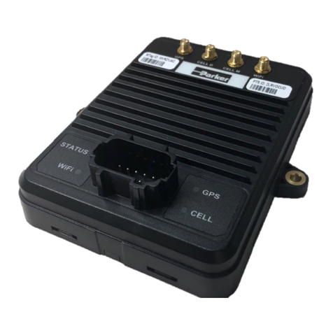
Figure 1: PVSG-IQAN-C2E1M1W1U1
The main features of the PVSG-IQAN hardware are listed in the following table:
PVSG-IQAN-C2E1M1W1U1
Characteristic
Description
Status LEDs
4 x tri-color
Communication
CAN x 2
Modem x 1
Wi-Fi x 1
Inputs
1 x Power Control)
External antenna connections
2 x SMA (GSM, GPS)
1 x RP-SMA (Wi-Fi)
RTC (Real Time Clock)
Powered with 10 year lithium battery
Connector
Deutsch DT16, 18 pin, key A

4 PSVG-IQAN-C2E1M1W1U1
About the PVSG-IQAN (Parker Vehicle System Gateway with IQAN Integration)
1.4. Ordering Part Numbers
The PVSG-IQAN gateway includes one part number all-inclusive of
cellular service, web portal service and IQAN Connect service for the
duration defined in the description. It is recommended that the Parker
antenna is used for optimum performance.
Part Number
Description
165341
6 Month trial. This part number includes a 6 month
contract for remote diagnostics, remote monitoring, and
250 MB per month of data.
165340
1 Year production part. This part number includes a 1
year contract for remote diagnostics, remote monitoring,
and 250 MB per month of data.
164632
3 Year production part. This part number includes a 3
year contract for remote diagnostics, remote monitoring,
and 250 MB per month of data.
164633
5 Year production part. This part number includes a 5
year contract for remote diagnostics, remote monitoring,
and 250 MB per month of data.
164634
Service Part. This is a replacement gateway that would
include just the hardware, provisioned to replace an
existing gateway. The service remaining on the device
will be applied at provisioning.
165788
20 ft Antenna. This part includes a 3 in 1 antenna. 3G
cellular, GPS and WiFi. The antenna comes with 20 ft
leads and right angle connectors.
165787
10 ft Antenna. This part includes a 3 in 1 antenna. 3G
cellular, GPS and WiFi. The antenna comes with 10 ft
leads and straight connectors

User Guide 5
Quick Start Guide
2.1. Getting Started using the Web Application
for Remote Monitoring
The PVSG-IQAN gateway pairs with the Voice of the Machine™cloud to enable a
number of IoT services. This section is meant as a quick start to create your assets
entity in the cloud. Please reference the online knowledge base for the most up to
date in depth training videos for the IQAN Connect cloud.
The knowledge base can be found at:
https://parkeriot.atlassian.net/wiki/x/RoJ6E
2.1.1. Requisite Information
You must have the following information available to create your asset in the IQAN
Connect cloud.
Login information for the users IQAN Connect cloud organization
The PTS Master tag ID
The PTS Master ID passed to your IQAN Connect organization.
The supplier of the PVSG-IQAN gateway is the main point of contact for
administering the log in information as well as making sure the Master tag has been
passed to the proper organization.
2. Quick Start Guide

6 PSVG-IQAN-C2E1M1W1U1
Quick Start Guide
The PTS Master ID can be found on the front of the module being installed on your
vehicle as shown in Figure 6.
2.1.2. Logging in and Creating the Asset
First the user must log into the web portal with their credentials.
The web portal can be accessed at:
https://parkermobileiot.com
After the user has logged into their organization they will be greeted with their fleet
overview page. The user must click the (+) button in the low right hand corner to
initiate the creation of the asset.
Figure 2. PTS Master Tag Location
Figure 3. IQAN Connect Fleet overview page.

User Guide 7
Quick Start Guide
A modal will appear as shown in Figure 9 below where you fill in the identifying
details and define which signals will be captured from the vehicle.
Figure 4. IQAN Connect asset creation modal.
The Master Tag field provides a searchable drop down list populated with
all of the Master Tags you have in your organization. As you begin typing
it will narrow the list.
The nickname is a configurable field that can be edited at any time
Serial number is a configurable field that can be edited at any time, we
recommend including the Master Tag in this field for the on-boarding
process of the vehicle
The template field is populated by a list of templates in your organization,
the template defines the configuration of the signals the gateway will log. It
is recommended to reference the knowledge base for more details on how
to configure a template.

8 PSVG-IQAN-C2E1M1W1U1
Quick Start Guide
2.2. Getting Started with Remote Monitoring
and Diagnostics with an IQAN System
The PVSG-IQAN gateway allows users to remotely connect to IQAN controllers in
the field over a cellular connection.
Note future remote updates to the gateway will allow users to use a WiFi network to
remotely connect to the vehicle.
2.2.1. Requirements
PVSG-IQAN gateway
Cellular Coverage
IQAN Connect service subscription
Gateway installed per Section 3 of the guide
Gateway connected to diagnostic bus of the IQAN system
Before starting your remote connection, ensure the gateway is powered up and the
status light is blinking green, indicating the gateway is connected to the IQAN
Connect servers.
2.2.2. IQAN Application Requirements
The PVSG-IQAN modem is in IQAN Design version 5.03+.
Note for more detailed instructions on the requirements for the IQAN application
please reference the help files within the IQAN Design software or the IQAN web
forum.
IQAN User Forum Link:
https://forum.iqan.se

User Guide 9
Quick Start Guide
The gateway module must be added to the IQAN application before remote
diagnostics can be performed and connected to the diagnostic bus. Select the GT
gateway using the add button in the IQAN system layout canvas. The modem is
listed under Gateway Modules. See Figure 5 for an example of the GT properly
configured in an IQAN system.
Figure 5. System Layout Canvas with PVSG properly connected to the diagnostic bus
The security section of the IQAN application must also be updated before remote
diagnostics can be performed. Under the security properties there are 3 options that
must be setup.
Figure 6. IQAN Design security settings for remote connectivity.

10 PSVG-IQAN-C2E1M1W1U1
Quick Start Guide
The security permissions are modifiable by an OEM or integrator, however the OEM
or integrator takes full responsibility to ensure that the proper safety guards are in
place to ensure that remote diagnostics cannot be performed in unsafe state.
2.2.3. Remotely Connecting to your IQAN system
After the PVSG-IQAN gateway has been installed, per section 3 and 4 of this
manual, the system is ready to connect. The user must next make sure the vehicle is
on, power is supplied to the system and the gateway is connected to the IQAN
Connect servers with the blinking green status light. There is no activation required,
the system will connect immediately.
Danger! Risk of death or injury. Ensure that the vehicle is in a
safe state before performing remote diagnostics or program
updates.
The user can remotely connect with both IQAN Design and IQAN Run.
Once running IQAN Run or design, select Communication from the top dropdown
menu and select Connect Remote to open the Connect via Internet window. You
must have IQAN Connect licenses to use this service. Contact your PVSG-IQAN
supplier for details on how to acquire the licenses.
If this is the first time the user is remotely connecting to this device, they must add
the system key. This can be found in the system menu of the IQAN module. For
example on an MD4-7 the key is displayed in the System Info page. Select Main
Menu then System and finally Info. The key can also be used as a system
information channel and displayed elsewhere in the program.

User Guide 11
Quick Start Guide
Once the user has the system key, they can enter it in IQAN Design or IQAN Run by
selecting the add button in the Connect via Internet window. This window will now
show the Master Tag or Machine ID and if the asset is online or offline every time
you access it. An example of the window is shown in Figure 4, note Master tag
I1GDENN is online.
The user choses the asset they would like to connect to and clicks the connect
button. While performing the update the system handshakes and communicates the
status to the user with pop up windows or status bars. For example, the system will
notify a user with a popup when there is a successful connection.
Figure 7. IQAN MD4-7 System info page.
Figure 8. IQAN Design remote connectivity.

12 PSVG-IQAN-C2E1M1W1U1
Quick Start Guide
Once the system confirms connection, the user can use any of the diagnostic tools
as if they were plugged directly into the back of the module.
Figure 9. Connection established confirmation
Table of contents
Other Parker Gateway manuals