PARKIT360 Transformer User manual

Parkit360
Transformer
1

Owner’s Manual
Introduction
We know you’re busy, and need to get that fifth wheel moved. Now. So with that
in mind, we’ve kept these instructions as brief as possible, but they are important,
so please take a moment and check them out.
We want to make sure that you enjoy years of safe and trouble-free operation
with your Parkit360 Transformer.
2

In The Box
The Parkit360 Transformer is shipped in one box on a pallet. The main Parkit360
Transformer unit will be fully assembled. In addition to the main unit the box will
3

also include:
Parkit360 Handle
(includes Allen Key)
Kingpin Adapter
(when purchased with Kingpin
Option: includes Kingpin adapter,
stabilizer bars, and hardware)
Ball Mount Kit
(when purchased with Ball Mount Kit
Option: includes: Ball Mount, Ball, Spring
Clips, and Tightening Bar)
4

Assembly
Please follow these steps to assemble the Parkit360 Transformer using the
assembled unit on page 2 as a guide:
Main Unit:
⦁ Insert the handle into the main unit as shown in Figure 1.1. Secure the
handle with the “D” Clip.
5

⦁ Install the battery (not included) in the battery box. Attach the red cable to
the positive terminal of the battery, and the black cable to the negative
terminal of the battery as shown below in figure 1.2.]
Note: The small White and Black wires in the picture are for the battery
charger.
The White wire is Positive (+) and the Black wire is Negative (-).
Note: The Parkit360 requires a 12-Volt, Group (size) 24 deep-cycle RV or
Marine battery. The battery is not included with the unit, and must be
purchased separately.
6

Transformer Wireless Remote Control Handle:
In the current Transformer models covered by this manual (Version 2.6), the
control handle is now detachable, and becomes the new remote control unit.
Simply remove the “D-Clip” and the handle can be removed from the mounting
tube.
Please note: Due to shipping regulations, the battery inside the control handle is
not connected. The handle cover is packaged separately inside the box.
Also, again due to shipping regulations and safety, the included lithium battery is
only charged to about 30% capacity, so it will need to be charged before first use.
The control handle will need to be assembled as follows:
⦁ Connect the charger cable as shown below. Please note that there is a
notch in the charger connector to ensure proper polarity.
7

⦁ Connect the battery charger port cable to the circuit board as shown
below. Make sure the connector is oriented so that the Red wire is at the
end labelled “+5” (RED) on the circuit board.
8

⦁ Once the battery and port cable connections have been made, position
the handle cover over the handle and secure the cover to the handle using
the four provided screws, as shown below:
9

Please read the safety information on the next page before using your
Parkit360 Transformer.
Safety
Please read the following safety notes before operating for the first time.
The Parkit360 Transformer is not recommended for use on hills due to the
possibility of a runaway trailer. The Parkit360 has been tested on grades up
to 4%. Operation on grades steeper than 4% is not recommended, and
could result in damage, injury, or death.
When using the Kingpin Option, the supplied stabilizer bars MUST BE
USED and installed properly. Failure to do so could damage both the unit
and your trailer.
The Parkit360 Transformer supports a maximum Kingpin weight of 2,500
lbs.
The maximum safe trailer weight for this unit is 16,000 lbs.
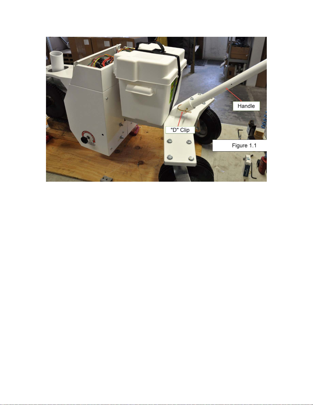
The unit’s main wheels operate in two modes: engaged, and freewheeling.
The freewheeling mode is to make the unit easy to move into position. The
10

wheels must NOT be in freewheeling mode when under load, or a runaway
trailer could result.
When charging the battery, it is important to keep the battery level;
otherwise, acid could seep out of the battery during the charging process.
Operation
Turning the Unit On and Off:
To turn on the unit, press and hold the On-Off button for two seconds.
The Blue LED will illuminate to indicate that the unit is On.
11

You will also hear a relay click inside the control module. This is the automatic
brake system engaging. If your 7-Pin trailer plug is connected to the Transformer,
the trailer brakes will be activated as soon as the power is turned on.
Wireless Remote Control Handle Operation:
For the following instructions, all of the directional terms used are from the point
of view of the user standing behind the unit during normal operation, for example,
when we refer to “Forward” this means that you are walking forward with the unit,
which would mean that the trailer is backing up.
The Parkit360 Transformer unit is controlled using two, three-position switches.
For both switches, the middle rocker position is off, or neutral.
12

Pressing the top of one of the wheel switches will result in that wheel moving the
unit forward, and pressing the bottom of one of the wheel switches will result in
that wheel moving the unit in reverse.
The switches may be operated individually, or together.
The wireless system in the handle is programmed to go to sleep after 30 seconds
of inactivity. This is normal, and is done to conserve the internal rechargeable
battery.
The wireless system will also go to sleep if the power is turned off.
The handle control system will “wake up” as soon as one of the rocker switches
is pushed.
13

The blue “Wireless Sync” LED in the handle control system will be on to indicate
successful wireless communication between the transmitter and receiver.
If the receiver is not on, the blue LED will blink slowly.
The blue light will blink rapidly if the battery in the handle is getting low and needs
to be recharged.
The supplied USB cable can be connected to the charging port on the handle,
and any standard USB phone charger can be used to recharge the battery.
The USB charge port is on the side of the handle, as shown below:
When charging, the “Battery Charge” light will be red, and will turn to green when
the battery is fully charged.
14

Trailer Brakes:
The Parkit360 Transformer features a connection for your trailer brake system.
When connected and powered on, the trailer brakes will be engaged
automatically whenever the unit isn’t moving.
Engaging the Wheels and Freewheel mode:
15

The knobs on the sides of the unit are used to change the wheels from engaged
to freewheeling mode.
Pull and turn the knobs (clockwise) to put the unit into freewheeling mode.
Pull and turn the knobs (clockwise) to re-engage the wheels.
To engage the wheels, it’s important that the knobs return to the fully seated position or
damage may occur to the transmission. When the unit is new, you may need to move
the unit, rocking the wheels back and forth a bit to make sure it’s properly seated.
16

Hooking up to the trailer:
If you use a Teflon thrust ring on your Kingpin, it must be removed before use.
⦁ Connect the Kingpin Adapter to the Kingpin and secure it in place with the
supplied locking U-Clip as shown. Once the U-Clip is in place, secure it
with the attached locking pin.
⦁ Attach and install the stabilizer bars. Begin by attaching the front end (the
Kingpin end) of the stabilizer bar in the Kingpin Adapter Collar using the
supplied D-Clips as shown below:
17

Important: Before attaching the stabilizer bars, please check to make
sure they are oriented properly by checking the fit at the front landing legs.
The tab at the leg end should fit to the outside of the front landing legs
(see photo in step 3).
⦁ Once the Kingpin end of the stabilizer bars are installed and secures,
attach the other end of the stabilizer bar to the front landing legs with the
supplied bolt and wing-nut as shown below:
18

Important: As shown in the picture, make sure to install the stabilizer bar
as close to the top of the leg as possible, ideally, right up against the
hydraulic part of the leg. Once the stabilizer bar is secured at both ends,
repeat steps 2 and 3 for the other stabilizer bar.
⦁ Once both ends of the stabilizer bars have been secured in place, raise
the trailer up high enough so that the Kingpin Receiver Tube can be
positioned under the Kingpin Adapter. Then move the Transformer so that
the unit is in place with the Kingpin Adapter directly above the Kingpin
Adapter Receiver Tube.
Important: Before proceeding, please make sure the trailer wheels are
chocked and that the Transformer is NOT in Freewheel mode.
⦁ Slowly lower the Kingpin Adapter directly into the Kingpin Adapter
Receiver Tube.
19

⦁ Raise the front landing legs and ensure that the entire weight is on the
Transformer.
Important: raise/adjust the front landing legs until the stabilizer bars are
as close to level as possible.
The following step (drilling the stabilizer bar) needs to be performed once only.
⦁ Once the Transformer is secure (not in Freewheel mode), the trailer
wheels are chocked, and the front landing legs have been raised so that
the stabilizer bars are as close to level as possible, you will need to drill
holes in each stabilizer bar to adjust and lock them in place. A guide hole
will be provided in the outer tube of each stabilizer bar (top and bottom),
and you will need to drill a hole through the inner tube so that a locking pin
can be inserted through the stabilizer bar.
The hole must allow a 3/8” pin, so pick an appropriate drill bit (13/32”) and
using the top hole as a guide, drill through the inner stabilizer bar tube.
20
Table of contents