parr 1108 Instruction Manual

205M
1108
Oxygen Combustion Vessel
Operating Instruction Manual

1108 Oxygen Combustion Vessel
Parr Instrument Company
2
Table of Contents
Preface
Scope — 3
Related Instructions — 3
Operating the 1108 Oxygen Combustion Vessel
Precautions — 4
Special Alloy Construction — 4
A Chlorine-Resistant Bomb — 4
1108B Oxygen Combustion Vessel — 4
Other Special Purpose Bombs — 4
Allowable Sample Size — 4
Attaching the Fuse — 5
Liquids in the Bomb — 5
Closing the Bomb — 5
Filling the Bomb — 6
Firing the Bomb — 6
Recovering the Combustion Products — 7
An Optional Recovery Procedure — 7
Samples and Sample Holders
Particle Size and Moisture Content — 8
Combustion Aids — 8
Sample Pellets — 8
Combustion Capsules — 8
Foodstuffs and Cellulosic Materials — 9
Coarse Samples — 9
Corrosive Samples — 9
Liquid Samples — 9
Gelatin Capsules — 9
Tape-Sealed Sample Holders — 10
Heavy Oils — 10
Explosives and High Energy Fuels — 10
Operating Suggestions
Poor Combustion — 11
Oxygen Charging Pressure — 11
Maintenance and Safety Instructions
Vessel Maintenance — 12
Vessel Repairs and ProofTests — 13
1108 Maintenance Checklist — 14
Parts
1108 Parts Diagram Key — 16
Parts for the 1108 Oxygen Combustion Vessel — 17
Parts for the 2901 Ignition Unit — 18
Parts for the 1825 Oxygen Filling Connection — 19

1108 Oxygen Combustion Vessel
www.parrinst.com 3
Customer Service
Questions concerning the installation or operation of this instrument
can be answered by the Parr Customer Service Department:
1-309-762-7716 • 1-800-872-7720 • Fax: 1-309-762-9453
E-mail: par[email protected] • http://www.parrinst.com
Preface
Scope
These instructions cover the procedures to be fol-
lowed when using a Parr 1108 Oxygen Combustion
Vessel to determine calorific values of solid or liquid
combustible material in a Parr calorimeter, or when
using an 1108 vessel in a 1901 Oxygen Vessel Appa-
ratus to prepare solid or liquid samples for chemical
analysis.The user should study these instructions
carefully in order to obtain a complete understanding
of the capabilities and limitations of an 1108 Oxygen
Combustion Vessel, and to be well aware of the pre-
cautions to be observed in its operation. Calorimeter
operations and the operation of various oxygen com-
bustion vessel accessories are described in separate
instruction manuals listed below, copies of which are
available upon request.
Related Instructions
No. Description
201M Limited Warranty
207M Analytical Methods for Oxygen Bombs
230M Safety in the Operation of Laboratory
and Pressure Vessels
483M Introduction to Bomb Calorimetry
Note About Nomenclature:
Historically, burning a sample enclosed in a high
pressure oxygen environment is known as Oxygen
Bomb Calorimetry and the vessel containing the
sample is known as an Oxygen Bomb. The terms
bomb and vessel are used interchangeably.

1108 Oxygen Combustion Vessel
Parr Instrument Company
4
Operating the 1108 Oxygen
Combustion Vessel
Precautions
Combustion with oxygen in a sealed bomb is a very
effective and reliable method for releasing all heat
energy obtainable from a sample and for preparing
hydrocarbon compounds and carbonaceous materi-
als for analysis, but there are certain precautions
which must always be observed when using this
equipment. In particular:
• Do not overcharge the bomb with too much
sample or with a sample which might react with
explosive violence.
• Do not overcharge the bomb with too much
oxygen.The initial charging pressure should not
exceed 40 atm (590 psig).
• Do not fire the bomb alone on an open bench
without providing a protective cooling medium.
The bomb should be completely submerged in
water during firing.
• Do not fire the bomb if gas bubbles are
released from any point on the bomb when it is
submerged in water.
• Do not ignite a volatile sample without using
one of the sealed sample holders described on
pages 8-9.
• Stand away from the bomb during and do not
handle the bomb for at least 6 minutes after
firing.
• Keep the bomb in good condition at all times.
Any parts that show signs of weakness or
deterioration must be replaced promptly.
• Read the maintenance and safety instructions
beginning on page 12 before starting to use the
bomb, and urge all operating personnel to re-
read these instructions often.
• Screw caps and cylinders are stamped so that
each cylinder and screw cap can be identified as
a matched set. We recommend that you maintain
the match of cylinders and screw caps for your
safety and ease of use.
Special Alloy Construction
The standard 1108 Oxygen Combustion Vessel is
made of a special columbium-stabilized stainless
steel selected for it’s excellent resistance to the
mixed nitric and sulfuric acids generated in a com-
bustion. It is a superior alloy which will withstand the
conditions generated in almost all fuel testing ap-
plications, yet neither it nor any other stainless steel
will resist the corrosive atmospheres produced when
burning samples containing halogen compounds.
For these applications, Parr offers the 1108CL Oxygen
Combustion Vessel described below. It should be
noted that all instructions for the 1108 apply equally
to the 1108CL as well.
A Chlorine-Resistant Bomb
The 1108CL Combustion Vessel is the same as the
standard 1108 model, but with a head and cylinder
made of an alloy with superior corrosion resistance
to the free chlorine and halogen acids released
when burning chlorinated samples. Users who
analyze waste materials and combustible solvents
are urged to select the 1108CL Combustion Ves-
sel instead of 1108 for its longer service life under
extreme corrosive conditions. Bomb maintenance
is also improved. In most cases, 1108CL returned
to the factory for scheduled maintenance can be
restored to optimum finish by repolishing instead of
having to rebore the cylinder to remove pits.
1108B Oxygen Combustion Vessel
The 1108B and 1108BCL Combustion Vessels are
identical to the 1108 and 1108CL models except for
the screw cap and cylinder. The 1108B and 1108BCL
have a heavy duty screw cap allowing for higher
energy release per sample. The cylinder has been
adapted to comply with Indian Standard IS 1350.
Other Special Purpose Bombs
Although the 1108 and 1108CL Combustion Vessels
will handle a broad range of test samples, Parr also
offers other special purpose combustion bombs,
including: a high pressure bomb for explosives, an
oversize bomb for large samples and a semi-micro
bomb for small samples. Separate operating instruc-
tions are issued for these special bombs.
Allowable Sample Size
To stay within safe limits, the bomb should never be
charged with a sample which will release more than
8000 calories (1108) or 10,000 calories (1108B) when
burned in oxygen, and the initial oxygen pressure
should never exceed 40 atmospheres (590 psig).
This generally limits the mass of the combustible
charge (sample plus benzoic acid, gelatin, firing oil
or any combustion aid) to not more than 1.1 grams.
When starting tests with new or unfamiliar materials
it is always best to use samples of less than 0.7 of a
gram, with the possibility of increasing the amount
if preliminary tests indicate no abnormal behavior.
To avoid damage to the bomb and possible injury
to the operator, it should be a standing rule in each
laboratory that the bomb must never be charged
with more than 1.5 grams of combustible material.

1108 Oxygen Combustion Vessel
www.parrinst.com 5
Attaching the Fuse
Set the bomb head on an A38A support stand and
fasten a 10 cm length of fuse wire between the two
electrodes. Parr 45C10 nickel alloy wire is used for
most tests, with platinum wire offered as an alter-
nate for certain special procedures.The 45C10 wire
is furnished on cards from which uniform 10 cm
lengths can be cut without further measurement.
Quick-grip electrodes now installed in all new 1108
Oxygen Combustion Vessels eliminate most of the
threading and twisting formerly required when bind-
ing the wire to plain electrodes.To attach the fuse to
quick-grip electrodes, insert the ends of the wire into
the eyelet at the end of each stem and push the cap
downward to pinch the wire into place. No further
threading or twisting is required.The procedure for
binding the fuse to the 4A and 5A plain electrodes
in older Parr vessels is illustrated in the instruc-
tion manual furnished with the original equipment.
For convenience, it is recommended that the user
purchase and install new 4A10 and 5A10 quick-grip
electrodes as replacements for the 4A and 5A styles
in older equipment.
Place the fuel capsule with its weighed sample in
the electrode loop and bend the wire downward to-
ward the surface of the charge as shown above. It is
not necessary to submerge the wire in a powdered
sample. In fact, better combustions will usually be
obtained if the loop of the fuse is set slightly above
the surface. When using pelleted samples, bend the
wire so that the loop bears against the top of the
pellet firmly enough to keep it from sliding against
the side of the capsule. It is also good practice to
tilt the capsule slightly to one side so that the flame
emerging from it will not impinge directly on the tip
of the straight electrode.
Liquids in the Bomb
Most combustion procedures call for a small amount
of liquid to be placed in the bottom of the bomb as
a sequestering agent and absorbent. If the amount
and type of liquid are not otherwise specified, add
1.0 mL of distilled or deionized water from a pipet.
Closing the Bomb
Care must be taken not to disturb the sample when
moving the bomb head from the support stand to
the bomb cylinder. Check the sealing ring to be sure
that it is in good condition and moisten it with a bit
of water so that it will slide freely into the cylinder;
then slide the head into the cylinder and push it
down as far as it will go. For easy insertion, push the
head straight down without twisting and leave the
gas release valve open during this operation. When
working with older bombs which have a removable
compression ring, be sure that the 104A2 ring is in
place above the gasket before attaching the screw
cap. Current model A416A3 Head Assemblies do not
require a separate compression ring. Set the screw
cap on the cylinder and turn it down firmly by hand
to a solid stop. When properly closed, no threads
on the cylinder should be exposed. If the screw cap
tends to bind to the cylinder at this point, indicating
that it might be difficult to open the bomb after it
has been fired, turn the screw cap back slightly – but
only a few degrees – enough to release the binding,
since the bottom thread must remain fully engaged.
It is not necessary to use a wrench or spanner on
the screw cap. Hand tightening should be sufficient
to secure a tight seal.
45C10 Fuse Wire
Set the bomb head on the A38A
support stand when attaching the
fuse and arranging the sample.
To attach the fuse: raise the cap,
insert the wire through the eye-
let, then pull the cap downward
to complete the assembly.
A38A Head Support & Stand Fuse Wire Fastened Between Two Electrodes

1108 Oxygen Combustion Vessel
Parr Instrument Company
6
Firing the Bomb
The electric current for
firing the bomb should
be drawn from a Parr
2901EB Ignition Unit
connected to an 115V
50/60Hz grounded elec-
trical outlet. (For 230V
50/60Hz use a 2901EE
Ignition Unit). Connect
one of the lead wires
from the calorimeter
to the 10 cm binding
post on the ignition unit
and the 2nd wire to the
middle or “common”
terminal.
When using the bomb in a calorimeter, insert the
421A lifting handle into the two holes in the side of
the screw cap and lower the bomb partially into the
calorimeter water bucket. Press the banana plugs
on the two ignition wires firmly into the terminal
sockets on the bomb head before the head is com-
pletely immersed in the water. After connecting
the wires, lower the bomb into the bucket with its
feet spanning the circular boss in the bottom of the
bucket. Remove the lifting handle and shake off any
drops of water back into the bucket. Be careful not to
remove any water from the bucket with the fingers.
When using the bomb alone for analytical purposes
it should be connected to the ignition unit as de-
scribed above and held submerged in an A387A or
similar water bath during firing.
In all operations, check the bomb for leaks before
firing. If any gas leakage is indicated, no matter how
slight, DO NOT FIRE THE BOMB. Instead remove it
from the water bath; release the pressure and elimi-
nate the leak before proceeding with combustion
test. If no leakage is indicated, adjust the water flow
rate so that the bomb will be covered by a continu-
ous flow of cold water during the firing period, then
stand back and press the firing button on the igni-
tion unit to fire the charge.
Caution: Do not have the head, hands or any
parts of the body directly over the bomb dur-
ing the firing period and do not go near the
bomb for at least 20 seconds after the firing.
Filling the Bomb
The instructions below de-
scribe a manual system us-
ing the 1825 Oxygen Filling
Connection furnished with
other Parr apparatus.
Oxygen for the bomb can
be drawn from a standard
commercial oxygen tank.
Unscrew the protective cap
from the tank and inspect
the threads on the valve out-
let to be sure they are clean
and in good condition. Place
the ball end of the connec-
tion into the outlet socket
and draw up the union nut
tightly with a wrench, keep-
ing the 0-55 atm gage in an
upright position.
The pressure connection to the bomb is made with
a slip connector on the oxygen hose which slides
over the gas inlet fitting on the bomb head. Slide
the connector onto the inlet valve body and push
it down as far as it will go. If it does not slide eas-
ily, a drop of water spread around the inlet valve
will lubricate the sealing rings. Older bombs use a
threaded connector with a knurled coupling which
must be turned finger tight.
Close the outlet valve on the bomb head; then open
or “crack” the oxygen tank valve not more than
one-quarter turn. Open the filling connection con-
trol valve slowly and watch the gage as the bomb
pressure rises to the desired filling pressure (usually
30 atm., but never more than 40 atm.); then close
the control valve. Release the residual pressure in
the filling hose by pushing downward on the lever
attached to the relief valve.The gage should now
return to zero.The bomb inlet check valve will close
automatically when the oxygen supply is shut off,
leaving the bomb filled to the highest pressure indi-
cated on the 0-55 atm. Gage. If the pressure drops
slowly and a large amount of gas escapes when the
pressure relief valve is opened, the check valve in
the bomb head is not operating properly.This trou-
ble will have to be corrected before the bomb can
be used. If too much oxygen should accidentally be
introduced into the bomb, DO NOT proceed with the
combustion. Detach the filling connection; exhaust
the bomb; remove the head and reweigh the sample
before repeating the filling operation.
2901 Ignition Unit
1825 Oxygen Filling
Connection

1108 Oxygen Combustion Vessel
www.parrinst.com 7
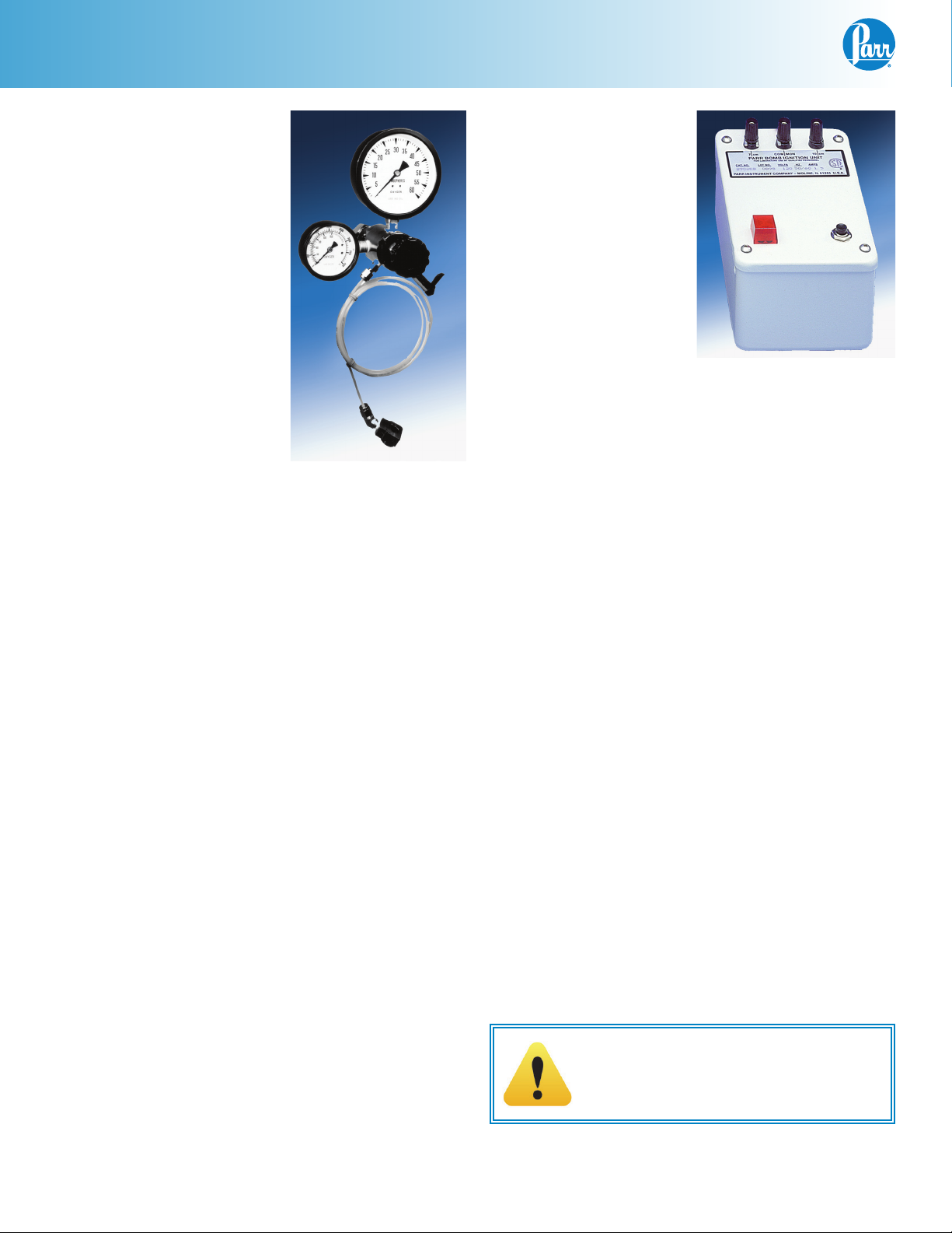
Fire the charge by pressing the firing button on the
ignition unit, keeping the circuit closed for about 5
seconds.The indicator light will come on when the
button is depressed and will remain on while cur-
rent flows through the fuse. When the fuse burns off
and breaks the circuit, the light will go out. Normally
this takes about ½ second, but it is good practice
to keep the push switch closed for about 5 seconds
regardless of the light. If the light continues to glow
while the button is depressed, there is either a short
circuit in the firing system or the fuse was not prop-
erly arranged. If a 26 gauge platinum wire is used to
fire the charge, hold the firing button down for only
one or two seconds which should be sufficient to ig-
nite the auxiliary fuse. A longer period may melt the
wire. If the wire melts, use the 7 cm terminals on the
ignition unit to obtain a lower firing voltage; or add
a heavy, one-ohm resistor to the 10 cm firing circuit
to lower the voltage.
If the indicator light does not come on when the
firing button is pressed there is either a fault in the
2901 or an open circuit in the system. Check for
voltage between the 10 cm and common termi-
nals of the 2901. Approximately 23 VAC should be
measured. If there is no voltage present, check the
fuse inside the 2901. An open circuit can usually be
located with an ohmmeter. Flex the lead wires dur-
ing any continuity check as the wires may be broken
and making only intermittent contact. If the red indi-
cator light glows during ignition but the bomb fuse
does not burn, check the system for a voltage leak
to ground, most likely in the insulated electrode on
the bomb head. Check the electrode using the high
impedance scale on an ohmmeter and replace the
electrode insulator and seal if leakage is indicated.
Recovering the Combustion Products
Let the bomb stand in the calorimeter or water bath
for at least 3 minutes, then lift it out of the water
and wipe with a clean towel. Open the valve knob
slightly to release all residual gas pressure before
attempting to remove the screw cap. Gas release
should proceed slowly over a period of not less than
one minute to avoid entrainment losses. After all
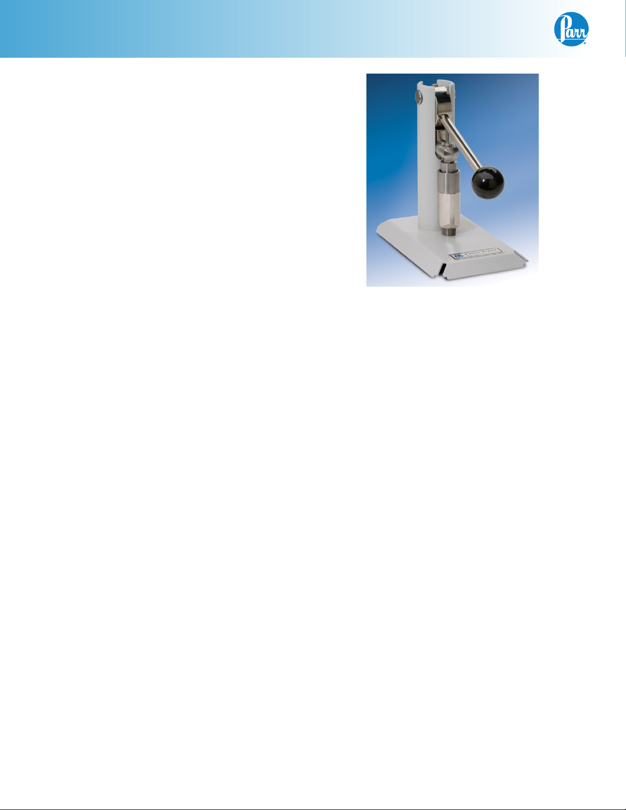
pressure has been released, unscrew the cap; lift the
head out of the cylinder and place it on the support
stand. Do not twist the head during removal. Pull it
straight out to avoid sticking. Examine the interior of
the bomb for soot or other evidence of incomplete
combustion. If such is found the test will have to be
discarded. Wash all interior surfaces of the bomb
and the combustion capsule with a jet of distilled
water and collect the washings. If any precipitate
or residue is present, remove it with a rubber po-
liceman. Do not filter the washings as this might
remove valuable constituents.Titrate the washings
and measure the unburned fuse wire as required for
calorific tests, then analyze the washings for sulfur
and other elements, if required.
Caution!
Do NOT have any part of the body in the
exhaust path of the bomb.
An Optional Recovery Procedure
If desired, a luer fitting, 518A, can be attached to the
bomb to provide a means for washing the bomb
and recovering the combustion products with a
syringe without opening the bomb and removing
the bomb head.To use this procedure, remove the
standard A420A valve needle and replace it with an
A420A2 needle to which a syringe, 244C, can be at-
tached.
To recover the combustion products via a luer fit-
ting, let the bomb stand in a cooling bath for at
least 3 minutes after firing to allow for complete
condensation of all residual vapor.Then remove the
bomb from the water and attach only the barrel of a
244C syringe to the luer fitting. Open the valve and
release the pressure at a slow rate, using at least
a full minute to bring the bomb pressure back to
atmospheric.The attached syringe barrel will help to
retain any condensate spray that might be carried
out of the valve during the exhaust period.
Add 30 mL of distilled water to the attached syringe
barrel and use the syringe plunge to force the water
into the bomb, then close the valve while holding
the plunger down.This will develop sufficient pres-
sure within the bomb to seat the inlet check valve
and provide enough positive pressure to help re-
move the washings. Agitate and rotate the bomb in
a horizontal position to wet all inner surfaces, then
turn the bomb upside down over a 600 mL beaker
and open the valve to discharge the washings into
the beaker.Tilt the bomb slightly toward the valve
to get as much of the water out as possible. Repeat
this back-flushing procedure two times, collecting
a total of 90 to 100 mL of washings, then open the
bomb and recover any liquid that may remain in the
cylinder.The three complete back flush and rinse
cycles should recover better than 99 percent of the
combustion products.

1108 Oxygen Combustion Vessel
Parr Instrument Company
8
Samples and Sample Holders
Particle Size and Moisture Content
Solid samples burn best in an oxygen bomb when
reduced to 60-mesh, or smaller, and compressed
into a pellet with a Parr Pellet Press. Particle size is
important because it influences the reaction rate.
Large particles may not burn completely and small
particles are easily swept out of the capsule by
turbulent gases during the rapid combustion. Com-
pression into a pellet is recommended since a pellet
burns less vigorously than a loose sample, resulting
in fewer incomplete combustions.
Materials such as coal burn well in the as-received
or air-dry condition, but do not burn bone-dry sam-
ples. A certain amount of moisture is desirable in
order to control the burning rate. Very dry samples
may burn so rapidly that a flame might reach the
seals or the soft valve seat in the bomb head, ignit-
ing these parts and possibly causing a serious burn-
out through the head. Moisture contents up to 20%
can be tolerated in many cases, but the optimum
moisture is best determined by trial combustions. If
moisture is to be added, drop water directly into a
loose sample or onto a pellet after the sample has
been weighed; then let the sample stand for awhile
to obtain uniform distribution.
Combustion Aids
Some samples may be difficult to ignite, or they
may burn so slowly that the particles become chilled
below the ignition point before complete combus-
tion is obtained. In such cases benzoic acid, white oil
or any other combustible material of known purity
can be mixed with the sample. Ethylene glycol,
butyl alcohol or decalin may also be used for this
purpose. It must be remembered, however, that a
combustion aid adds to the total energy released in
the bomb and the amount of sample may have to be
reduced to compensate for the added charge. If ben-
zoic acid is added as a combustion aid, it must be
added in a pellet form, .2 gm pellets. Never combust
benzoic acid in powder form.
Sample Pellets
One of the most useful techniques for handling
powdered samples is to compress the material into
a tablet or pellet before it is weighed. Pellets are
easier to handle than loose samples and they burn
slower in the bomb, thereby reducing the chances
for incomplete combustion.The Parr pellet press
offers a convenient means for preparing samples
in this manner. Pellets produced in this press are
ejected into a stainless steel receiver from which
they can be lifted and handled easily with a pair of
forceps. Most pellets for use in the 1108 Oxygen
Combustion Vessel are made in a one-half inch di-
ameter size, but smaller diameters can be produced
in the same press using interchangeable punch and
die sets. Complete pellet making instructions are
furnished with each press.
Combustion Capsules
Non-volatile samples to be tested in Parr Oxygen
Combustion Vessels are weighed and burned in
shallow capsules measuring approximately 1”
dia. and 7/16” deep. These are available in stain-
less steel, fused silica and platinum alloyed with
a 3-1/2% rhodium. Stainless steel capsules are
suitable for all tests except those in which a non-
metallic (fused silica) holder is desired or where
the superior corrosion resistance of a Pt-Rh cup is
required. Fused silica capsules should be used for
samples containing dissolved metals which can
ignite a stainless steel capsule and cause serious
bomb damage.
Stainless steel capsules will soon acquire a dull grey
finish after repeated use in an oxygen bomb due to
the formation of a hard, protective oxide film.This
dull finish not only protects the capsule but it also
promotes combustion and makes it easier to burn
the last traces of the sample. It is recommended,
therefore, that capsules be heated in a muffle fur-
nace at 500°C for 24 hours to develop this protective
coating uniformly on all surfaces.This treatment
should be performed after a capsule has been pol-
ished with an abrasive to remove any ash or other
surface deposits. Heating in a muffle is also a good
2811 Pellet Press

1108 Oxygen Combustion Vessel
www.parrinst.com 9
way to destroy any trace of carbon or combustible
matter which might remain in the capsule from a
previous test. After heating, place the capsules in a
clean container and handle them only with forceps
when they are removed to be weighed on an ana-
lytical balance.
Capsules should be monitored for wear. Do not use
the capsule if the wall or base thickness is less than
0.025”.
Foodstuffs and Cellulosic Materials
Fibrous and fluffy materials such as vegetable fibers
may have to be packed into the combustion capsule
and moistened to slow the burning rate, but food-
stuffs and cellulosic samples generally burn with
little difficulty. Partial drying may be necessary if the
moisture content is too high to obtain ignition. But
if the sample is heat sensitive and cannot be dried,
a water soluble combustion aid such as ethylene
glycol can be added to promote ignition.
Coarse Samples
In most cases it may be necessary to burn coarse
samples without size reduction since grinding or
drying may introduce unwanted changes. There is
no objection to this if the coarse sample will ig-
nite and burn completely. Whole wheat grains and
coarse charcoal chunks are typical of materials
which will burn satisfactorily without grinding and
with no additives or special procedure.
Corrosive Samples
Although the Parr Oxygen Combustion Vessel is
made of corrosion resistant alloys, repeated use
with high sulfur samples or with samples contain-
ing over 20 mg of chlorine may corrode the metal
surfaces and produce a dull film on the inner walls
of the bomb. Materials containing appreciable
amounts of caustic; such as dried black liquor from
a pulp mill, may also damage the bomb, with the
caustic attacking the alloy capsule and causing the
metal capsule and the bomb electrodes to ignite and
burn.These corrosive attacks on the bomb can be
reduced by using smaller samples and by increas-
ing the amount of liquid placed in the bottom of
the bomb. If a corrosive film develops on the bomb
surfaces it should be removed by proper polishing
before it grows to a point where deep pitting occurs.
Liquid Samples
Non-volatile samples are treated in the same man-
ner as solid materials. Oils and other liquids which
are not volatile at room temperature can be weighed
directly into open combustion capsules.The loop of
the fuse should be positioned just slightly above the
surface of the sample. Some operators place one
end of a short piece of fine cotton thread over the
fuse loop, with the other end touching the liquid. In
any case, the wire itself should not be submerged in
the liquid.
Gelatin Capsules
Volatile liquid samples to be burned in an oxygen
bomb can be handled conveniently in Parr 3601
Gelatin Capsules.These 0.9 mL capsules consist of
two cups which telescope together with a friction fit
adequate to retain most liquids. Corrections must
be made for the heat of combustion of gelatin (ap-
proximately 4600 cal/g) if the capsules are used for
43A6 Combustion Capsule with
Adhesive Tape Seal
3601 Gelatin Capsules 43AS Combustion Capsules

1108 Oxygen Combustion Vessel
Parr Instrument Company
10
calorimetry, and for the sulfur content of the gelatin
(approximately 0.35%) if used for sulfur determina-
tions. Blank tests must be run to determine the exact
amounts. Gelatin capsules should always be stored
in sealed bottles and handled with due regard for
their hygroscopic nature.
The blank tests should be repeated at frequent inter-
vals since values determined on a weight basis will
change if there are variations in the moisture con-
tent of the gelatin.
Tape-Sealed Sample Holders
Volatile samples can be handled in a standard 43AS
combustion capsule with a flat top rim, or in a 43A6
platinum capsule with a spun rim by covering the top
of the capsule with a disc of adhesive plastic tape.
To seal a capsule; stretch a piece of tape across the
top and press it firmly against the rim with a flat
blade, then trim the excess with a sharp knife. The
seal obtained in this manner will be adequate to re-
tain most volatile samples.The tape used for this pur-
pose should be free of chlorine and as low in sulfur
as possible. Borden “Mystic Tape” No. M-169-C, or
3M Transparent Tape No. 610 are recommended for
this purpose. Equivalent tape can be obtained from
Parr under Part No. 517A.The weight of the tape disc
must be determined separately and a correction ap-
plied for any elements in the tape which might in-
terfere with the determination. This can be done by
running a blank test with the tape alone using a sam-
ple weighing about 1.0 gram. Tape should always be
stored in a sealed container to minimize changes in
its moisture content.
Use the following procedure when filling and han-
dling any of these tape-sealed sample holders;
Weigh the empty cup or capsule; then cover the top
with tape, trim with a knife and press the trimmed
edge firmly against the metal rim. Also cut and at-
tach a small flag to the disc; as illustrated at the top
of page 9. Puncture the tape at a point below the
flag, then reweigh the empty cup with its tape cover.
Add the sample with a hypodermic syringe; close the
opening with the flag and reweigh the filled cup. Set
the cup in the loop electrode and arrange the fuse
wire so that it touches the center of the tape disc.
Just before closing the bomb, prick the disc with
a sharp needle to make a small opening which is
needed to prevent collapse of the disc when pres-
sure is applied. Fill the bomb with oxygen to the
usual charging pressure, but add oxygen slowly so
that the tape will not collapse into the cup. Fire the
bomb and complete the test in the usual manner.
Low volatile samples with a high water content,
such as urine or blood, can be burned in an open
capsule by absorbing the liquid on filter paper pulp
or by adding a combustion aid, such as ethylene
glycol or by freeze drying the sample.
Heavy Oils
Oils and other liquids which are not volatile at room
temperature can be weighed directly into open
combustion capsules.The loop of the fuse should
be positioned just slightly above the surface of the
sample. Some operators place one end of a short
piece of fine cotton thread over the fuse loop, with
the other end touching the liquid. In any case, the
fuse wire itself should not be submerged in the
liquid.
Several precautions must be observed when testing
heavy oils because of the intense heat which they
develop. If the wall of the metal combustion capsule
is thin, or if some of the sample happens to have
been spread on the thin rim of the capsule, it is pos-
sible that the metal may become heated to the point
where it will ignite.This condition is serious because
of the excessive heat liberated when metal burns in
oxygen. Also, the molten metal oxides may damage
the interior of the bomb. In extreme cases the bomb
electrodes may also ignite and burn with similar
results. For these reasons, be sure that any capsule
holding a heavy oil is in good condition and not
worn thin from prior usage. Also, bend the straight
electrode so that it does not project over the cup
where it will receive the full flame from the sample.
It is always desirable to tilt the capsule slightly in the
loop holder so as to direct the flame away from both
electrodes. Some operators prefer to use a 10 to 13
mL platinum crucible for holding heavy oil samples
because the added depth in a crucible promotes
slower combustion and a milder flame.
Explosives and High Energy Fuels
Special precautions must be observed when testing
materials which release large volumes of gas upon
ignition, or which detonate with explosive force. Al-
though most slow-burning gun powders and rocket
propellants can be tested in the conventional 1108
Oxygen Combustion Vessel, the user must under-
stand that this bomb is not designed to withstand
the shock pressures produced by primers and high
explosives. It is much safer to test these materials in
a Parr 1104 High Pressure Oxygen Vessel.

1108 Oxygen Combustion Vessel
www.parrinst.com 11
Operating Suggestions
Poor Combustion
The difference in combustion characteristics of the
wide variety of materials which may be burned in an
oxygen bomb make it difficult to give specific direc-
tions which will assure complete combustions for all
samples. However, two fundamental conditions may
be stated. First, some part of the sample must be
heated to its ignition temperature to start the com-
bustion and, in burning, it must liberate sufficient
heat to support its own combustion regardless of
the chilling effect of the adjacent metal parts. Sec-
ond, the combustion must produce sufficient turbu-
lence within the bomb to bring oxygen into the fuel
cup for burning the last traces of the sample.
An incomplete combustion in an oxygen bomb is
nearly always due to one or more of the following
causes:
1. Excessively rapid admission of gas to the bomb
during charging, causing part of the sample to
be blown out of the cup.
2. Loose or powdery condition of the sample which
will permit unburned particles to be ejected
during a violent combustion.
3. The use of a sample containing coarse particles
which will not burn readily. Coal particles which
are too large to pass a 60-mesh screen may not
burn completely.
4. The use of a sample pellet which has been made
too hard or too soft. Either condition sometimes
causes spalling and the ejection of unburned
fragments.
5. The use of an ignition current too low to ignite
the charge, or too high, causing the fuse to break
before combustion is under way.
6. Insertion of the fuse wire loop below the surface
of a loose sample. Best results are obtained by
barely touching the surface or by having the
wire slightly above the sample.
7. The use of insufficient oxygen to burn the
charge, or conversely, the use of a very high
initial gas pressure which may retard the
development of sufficient gas turbulence within
the bomb.
8. Insufficient space between the combustion
cup and the bottom of the bomb.The bottom
of the cup should always be at least one-half
inch above the bottom of the bomb, or above
the liquid level in the bomb, to prevent thermal
quenching.
9. Excessive moisture or non-combustible material
in the sample amounts to approximately 20
percent or more of the charge it may be difficult
to obtain complete combustion.This condition
can be remedied by adding a small amount of
benzoic acid or other combustion aid.
Oxygen Charging Pressure
Operators sometimes disagree as to the most
desirable oxygen charging pressure. As a rule, it is
best to use the lowest gas pressure that will give
complete combustion. Lower pressures permit
higher gas temperatures and greater turbulence,
both of which help to secure better combustion.
The range of charging pressures for Parr Oxygen
Combustion Vessels usually falls between 25 and 35
atmospheres, and it should never exceed 40 atmo-
spheres.

1108 Oxygen Combustion Vessel
Parr Instrument Company
12
Maintenance and Safety Instructions
Bomb Maintenance
Under normal usage Parr oxygen combustion ves-
sels will give long service if handled with reason-
able care. However, the user must remember that
these bombs are continually subjected to high
temperatures and pressures which apply heavy
stresses to the sealing mechanism.The mechanical
condition of the bomb must therefore be watched
carefully and any parts that show signs of weakness
or deterioration should be replaced before they fail.
Otherwise, a serious accident may occur.
Do not fire the bomb if gas bubbles are observed
anywhere indicating a possible gas leak. Disas-
semble the parts and install new seals immediately.
The bomb head parts which require closest attention
and most frequent replacement are: the 230A O-ring
head gasket, all the 238A sealing rings, the 415A
O-ring and the 20VB PCTFE valve seat in the needle
valve.
When replacing the 230A head gasket, stretch the
new O-ring and let it snap into place to be sure that
it moves freely in its groove and is not twisted.
The 20VB valve seat in the needle valve deteriorates
with use, not only in the needle area but on the un-
derside of the seat as well. Leakage and a possible
serious burn-out can result from a worn or damaged
seat if it is not replaced promptly. As a basic rule,
the 20VB valve seat and the two 238A O-rings on
the valve needle should be replaced after every 500
firings or every six months, whichever occurs first.
If the bomb is used for samples containing chlorine,
these parts should be replaced after every 250 fir-
ings.
To replace the valve seat, unscrew the 397A com-
pression nut; remove the valve stem and the old
seat, and disassemble all of the parts. Drop a new
20VB valve seat into the body and push it down
into place. Slide a 7VBCM Monel washer, two 238A
O-rings and the 378A packing cup onto the A420A
valve needle assembly with the needle pointed up-
ward; then adjust the parts on the needle so that the
tip of the needle is flush with-or slightly recessed
into-the bottom of the packing cup. Insert this as-
sembly into the 396A outlet valve body and press it
firmly against the valve seat by tightening the 397A
compression nut to 100 inch-pounds of torque.
A Parr 475A Service Clamp offers a convenient
means for clamping the bomb head firmly in a vise
without damaging the head when replacing any of
the bomb head parts.
Keep the 397A compression nut on the valve needle
tightened firmly at all times. Frequent tightening
is important.This nut, if slightly loose, may allow a
leak to develop during the rapid pressure rise upon
ignition.This type of leak may not be detectable be-
fore firing; but if it develops, the hot gases can ignite
the 20VB valve seat and burn through the head.
Do not use extreme force when closing the needle
valve. A moderate but firm turn on the valve knob
should be sufficient to stop all gas flow. Excessive
needle pressure will deform and possibly close the
gas passage. If this happens, unscrew the valve
body and replace the 20VB valve seat. Accumulated
salt deposits may also clog the gas passage, mak-
ing it difficult to release pressure at the end of a run.
To avoid this, clean the passage through the valve
needle and deflector nut with a small drill.
The 238A sealing ring in the insulated electrode
should be replaced with the same frequency as the
20VB valve seat. Also, keep the 411A terminal nut
tight at all times. As the 238A sealing ring ages and
hardens it becomes a partial electrical conductor,
permitting misfires and producing unwanted heat-
ing effects. Periodic replacement will eliminate this
potential problem.
The threads on the screw cap should be checked
routinely for any burns or other deformity. After
long use, the threads on the screw cap may become
worn to the point where they will no longer provide
a safe closure for the bomb, and the screw cap will
have to be replaced.The following procedure can be
used to check the extent to which the threads have
become worn:

1108 Oxygen Combustion Vessel
www.parrinst.com 13
1. Assemble the bomb with the head in the cyl-
inder and count the number of turns required
to bring the screw cap down firmly against the
head.
2. Then open the bomb; remove the head and
replace the screw cap, but turn it down to only
one-half of the turns previously counted.This
will usually be about four turns.
3. With the screw cap in this position, use a dial
gage to measure the vertical deflection when
lifting the screw cap upward. If this measure-
ment exceeds 1/32 inch (0.030”), the screw cap is
unsafe and should be discarded.
4. The cylinder can then be returned to the fac-
tory for inspection. If the threads on the cylinder
are in good condition, a new screw cap can be
custom-fitted to the cylinder.
Never under any circumstances use oil on the O-
rings which seals the bomb head or on any of the
valves or fittings which handle compressed oxygen.
This precaution applies to all of the oxygen bomb
parts to the oxygen filling connection as well.
Although Parr oxygen combustion vessels are made
from alloys which will withstand most corrosive
gases, these bombs will not resist chlorine, fluorine
or bromine in the presence of moisture. If samples
yielding appreciable amounts of these elements are
burned in a Parr vessel, the interior surfaces may
become etched or corroded. In such cases the bomb
should be emptied and washed as quickly as pos-
sible after each combustion.
If the interior of the bomb should become etched
as mentioned above, the resistance of the metal
to further attack can be improved by restoring the
surface to its original highly polished condition.
Bombs needing repolishing or other repair work can
be returned to the factory. A periodic overhaul and
test at the factory will help to keep any Parr oxygen
combustion vessel in first-class condition.
See page 14 for a Maintenance Checklist.
Bomb Repairs and ProofTests
The 20VB valve seat, 230A, 415A, and the four 238A
O-rings should be replaced after every 500 firings,
or every six months, whichever occurs first. If the
bomb is used for samples containing chlorine, these
repairs should be made after every 250 firings. Parr
oxygen combustion vessels can be returned at any
time for repair and testing. A factory test is recom-
mended after every 5000 firings, or after any of the
following conditions; (a) fired with an excessive
charge, (b) ignition of any internal components,
(c) machined by any source other than the factory,
(d) damaged by corrosive vapors that might have
exceeded 80% of the corrosion allowance, or (e) any
changes in the threads on the bomb cylinder and/or
screw cap.
When returning a oxygen combustion vessel to the
factory, ship it to:
Parr Instrument Company
Attn: Repair Department
211- 53rd Street
Moline, Illinois 61265
A purchase order covering the repair work should be
included with the shipment or mailed to the same
address as no repairs will be started without specific
instructions. Be sure to include a return shipping
address and the name and telephone number of the
individual to be contacted if questions arise con-
cerning excessive repair costs or other problems.
Individual repair parts can be ordered from any Parr
dealer or direct from the factory.

1108 Oxygen Combustion Vessel
Parr Instrument Company
14
1108 Maintenance Checklist
Refer to page 12-13 & 16-17 of the 1108 Operating Instruction Manual for assembly instructions and parts
diagram.
500 Test Maintenance
Replace the following:
Date Date Date Date
410A
415A
238A (4)
143AC
20VB
Examine and replace if worn or cracked.
143AC
401A
96AC

Notes
www.parrinst.com 15

1108 Oxygen Combustion Vessel
Parr Instrument Company
16
Key Item Description
1 103A
103A6
Screw Cap
Screw Cap, Heavy Duty (1108B)
2 230A O-ring 2-3/8 ID Buna-N
3 394A12
394A12CL
Head, Bare
Head for Chlorine Service
4101A
101A4
101ACL
101A4CL
Vessel Cylinder sold as Part No. AA101A
Vessel Cylinder sold as Part No. AA101A4 (1108B)
Vessel Cylinder for Chlorine Service sold as Part No. AA101ACL
Vessel Cylinder for Chlorine Service sold as Part No. AA101A4CL (1108B)
5 395A2 Inlet Valve Body
6 415A O-ring 7/16 ID Buna-N
7 238A O-ring 3/16 ID Buna-N
8 403A Check Valve
9 411A Terminal Nut
10 143AC Insulator Delrin
11 238A O-ring 3/16 ID Buna-N
12 388A Spacer
13 SC1932SC10 Socket Head Set Screw
14 278A3 Adapter Bushing
15 404A2 Deflector Nut
16 406A Lock Nut
17 5A10 Loop Electrode with Sleeve
18 4A10 Straight Electrode with Sleeve
19 401A Sleeve Insulator
20 96AC Electrode Insulator
21 402A Electrode Core
22 406A Lock Nut
23 407A Valve Knob
24 398A Lock Nut
25 400A
A420A
Valve Needle
Valve Needle with Knob (Nos. 23, 24, 25)
26 397A Compression Nut
27 396A Outlet Valve Body
28 7VBCM Washer Monel
29 378A Packing Cup
30 20VB Valve Seat PCTFE
Item Complete Assemblies
AA101A Vessel Cylinder with 103A Screw Cap
AA101A4 Vessel Cylinder with 103A6 Screw Cap (1108B)
AA101ACL Vessel Cylinder for Chlorine Service with 103A Screw Cap
AA101A4CL Vessel Cylinder for Chlorine Service with 103A6 Screw Cap (1108B)
A416A3 Vessel Head Assembly
A416A3CL Vessel Head Assembly for Chlorine Service
Parts
1108 Parts Diagram Key

1108 Oxygen Combustion Vessel
www.parrinst.com 17
Parts for the 1108 Oxygen Combustion Vessel
1
3
10
30
28 9
19
KEY No. PART No. DESCRIPTION
AA101A............BOMB CYLINDER WITH 103A SCREW CAP
AA101ACL.......BOMB CYLINDER FOR CHLORINE SERVICE WITH 103A SCREW CAP
A416A3............BOMB HEAD ASSEMBLY
A416A3CL........BOMB HEAD ASSEMBLY FOR CHLORINE SERVICE
COMPLETE ASSEMBLIES
2
4
5
6
8
7
11
9
29
7
7
27
26
25
24
23
13
12
15
20
21
22
18
15
14
16
17
1
2
3
4
5
6
7
8
9
10
11
12
13
14
15
16
17
18
19
20
21
22
23
24
25
26
27
28
29
30
103A
230A
394A12
394A12CL
A101A
A101ACL
395A2
415A
238A
403A
411A
143AC
238A
388A
SC1932SC10
278A3
404A2
406A
5A10
4A10
401A
96AC
402A
406A
407A
398A
400A
A420A
397A
396A
7VBCM
378A
20VB
SCREW CAP
O-RING 2-3/8 ID BUNA-N
BOMB HEAD, BARE
BOMB HEAD FOR
CHLORINE SERVICE
BOMB CYLINDER SOLD ONLY
WITH 103A SCREW CAP AS
PART No. AA101A
BOMB CYLINDER SOLD ONLY
WITH 103A SCREW CAP AS
PART No. AA101ACL
INLET VALVE BODY
O-RING 7/16 ID BUNA-N
O-RING 3/16 ID BUNA-N
CHECK VALVE
TERMINAL NUT
INSULATOR DELRIN
O-RING 3/16 ID BUNA-N
SPACER
SOCKET HEAD SET SCREW
ADAPTER BUSHING
DEFLECTOR NUT
LOCK NUT
LOOP ELECTRODE W/SLEEVE
STRAIGHT ELECTRODE W/SLEEVE
SLEEVE INSULATOR
ELECTRODE INSULATOR
ELECTRODE CORE
LOCK NUT
VALVE KNOB
LOCK NUT
VALVE NEEDLE
VALVE NEEDLE W/KNOB
(Nos. 23, 24, 25)
COMPRESSION NUT
OUTLET VALVE BODY
WASHER MONEL
PACKING NUT
VALVE SEAT KEL-F
APPROVED
BY
BY
SCALE
DWG NO.
DATE
DRAWN
DESCRIPTION
REVISIONS
FOR
DATE
1108 PARTS IDENTIFICATION
08-09-05
1:1
CWJ
SIZE
C
1108
08-09-05 PJC
PROPRIETARY
NEITHER THE DRAWING
NOR INFORMATION
CONTAINED HEREIN
MAY BE COPIED,
REPRODUCED, OR
OTHERWISE USED
WITHOUT WRITTEN
PERMISSION FROM
PARR INSTRUMENT
COMPANY.
DRAWN IN 3rd ANGLE PROJECTION DO NOT SCALE DRAWING
MOLINE, ILLINOIS 61265
211 53rd STREET
PARR INSTRUMENT CO.
RWOC; 02-08-08 MAW
SHEET 2
480M
REF: 4558AK

1108 Oxygen Combustion Vessel
Parr Instrument Company
18
Parts for the 2901 Ignition Unit
200F11
8
12
12V
12
7
115V
12
11
8
7
6
2
5
6
4
3
5
4
3
8
115V
9
9
2
12V
711
11
1
10 10
2
6
1
1
139E21
1157E
W/ SA1332RP04
(10 cm)
ISO WARNING SYMBOL
TN1632HL
COVER
CHASSIS
2005E
A3299HC
W/(4) UP18DM04
1557E REF
(LOAD)
190F
2014E
REF
1575E
A3299HC
1576E
REF
(COMMON)
REF
174F
GROUND SYMBOL
1574E
MOUNT TRANSFORMER
2000E
A1580E
(3) TN1332HL
(7 cm)
34E2
REF
95F
(3) A59A2
Item Description
A1673E2 Kit Electric Parts for 2901EB/EE
1203EEE Cord 10A/220V Cont Europe Plug
1202EEE Cord 13A/220V BS Plug
2000E Transformer, 120/240 VAC 24V
XB0010 1/8ID Shrink Tubing Black
34E2 Cord w/ 115VAC Plug 18-3SJT
A3299HC Box Assembly, Ignition Unit 115V
A3299HC2 Box Assembly, Ignition Unit 230V
2005E Strain Relief Pigtail Black
2005E2 Strain Relief Pigtail Black, for 230V
139E21 Fuse 3AG Slo-Blo 250V 5.0 Amp (115 volt units)
139E8 Fuse 3AG Slo-Blo 250V 2.5 Amp (230 volt units)
1157E Fuse Holder, 3AG x 1/4 Tab
SA1332RP04 6-32 x 1/4 RHMS Phillips 18-8
Caution!
For continued protection against possible hazard, replace fuses with same type and rating of fuse.
2901 Ignition Unit

1108 Oxygen Combustion Vessel
www.parrinst.com 19
Parts for the 1825 Oxygen Filling Connection
Item Description
4VB3 Packing gasket
6VBBB Packing cover, brass
8VB2 Packing nut
9VB1 Union nut, brass, CGA540
20VB Valve seat, PCTFE
21VBBB Lantern ring, brass
53A Oxygen gage, 3-1/2”, 0-60 atm
112VB4AK Valve needle
124VB Union nipple, brass, CGA540
A140VB Toggle relief valve
A150VB Valve knob
188A2 Filling connection body, bare
243VB Tube connector, male
438VB Elbow connector, 45°, male
A476A3 Slip connector with O-rings
394HCJE O-ring for A476A3 slip connector (2 required)
HX0012TB024 Pressure tubing, 1/8” OD, Nylon, 5-ft
1825 Oxygen Fill Connection

Revision 08/26/13
Table of contents
Other parr Industrial Equipment manuals
Popular Industrial Equipment manuals by other brands

Seifert
Seifert 751200B001 user manual

Roper Whitney
Roper Whitney 816 Installation, operation and maintenance manual

SCHUNK
SCHUNK ROTA FSW Assembly and operating manual

Pasco Scientific
Pasco Scientific WA-9401 Instruction manual and experiment guide

Kval
Kval 990-APEX quick start

Sima
Sima CAT 202 Original user manual

Nordson
Nordson Vulcan Jet Customer product manual

SIAM
SIAM SUDOS-mini 2 operating manual

Thermo Scientific
Thermo Scientific CTS Xenon installation guide

ECKELMANN
ECKELMANN E-Control CNC Product documentation

Zimmer
Zimmer MATCH LWR50F-01-03-A Installation and operating instructions

SICK
SICK VMS4100 operating instructions