parr 6400 Instruction Manual

6400 Automatic Isoperibol Calorimeter
Operating Instruction Manual

Table of Contents
1
PREFACE
Scope 4
Related Instructions 4
Purpose 4
Intended Usage 4
Explanation of Symbols 5
Safety Information 5
General Specifications 5
Environmental Conditions 6
Provisions for Lifting and Carrying 6
Cleaning & Maintenance 6
Getting Started 6
CHAPTER 1
CONCEPT OF OPERATION 8
A Highly Automated Procedure 8
New Convenience and New Technology 8
Isoperibol Operation 8
Dynamic Operation 9
Full Microprocessor Based Process Control 9
Full Microprocessor Based Data Acquisition & Handling 9
Flexible Programming 9
CHAPTER 2
INSTALLATION 10
Environmental Conditions 10
Required Consumables, Utilities & Power Requirements 10
Electrical Connection 10
Front Panel Meter 10
Swagelok Tube Fittings 11
6400 Calorimeter Installation Guide Video 11
Water Connection 13
Gas Connection 14
Combustion Vessel Exhaust Connections 14
Communication Connections 15
Printer and Balance Connections 15
CHAPTER 3
PROGRAM INSTALLATION & CONTROL 16
Programming 16
Default Settings 16
User Default Settings 16
Factory Default Settings 16
CHAPTER 4
OPERATION 18
Initial Fill 18
Quick Start 18
Sample Preparation 19
Sample Size 19
Particle Size and Moisture Content 19
Sample Types 20
Foodstuffs and Cellulosic Materials 20
Coarse Samples 20
Corrosive Samples 20
Explosives and High Energy Fuels 20
Volatile Sample Holders 20
Combustion Aids 21
Combustion Capsules 21
Test Process 22
Loading the sample 22
Closing the Oxygen Combustion Vessel 22
Fill Cycle 23
Pre-Period 24
Oxygen Combustion Vessel Firing 24
Post-Period 24
Cool/Rinse 25
Drain 26
CHAPTER 5
MENU DESCRIPTIONS 28
Menu System 28
Menu Keys 28
Control Keys 28
Calorimeter Operation 29
Temperature vs. Time Plot 29
Temperature Plot Setup 29
Operating Controls 30
Spiking Controls 30
Bomb Rinse Tank Controls 31
Program Information & Control 32
Software & Hardware Info 32
User/Factory Settings 32
Calibration Data and Controls 33
Bomb 1 34
Control Plot Chart Plot 35
Thermochemical Corrections 35
Calculation Factors 36
Net Heat/Dry Factors 37

Table of Contents
2
Data Entry Controls 38
Net Heat Data Entry Controls 38
Auto Sample ID Controls 38
Moisture Data Entry Controls 39
Preweigh Sample ID Controls 39
Reporting Controls 40
Communication Controls 40
Balance Port Communications 40
Balance Port Settings 41
File Management 42
Run Data File Manager 42
Diagnostics 43
Data Logger Controls 43
Data Log Items 43
I/O Diagnostics: 44
CHAPTER 6
STANDARDIZATIONS 46
Standardizing the Calorimeter 46
The Energy Equivalent Factor 46
Standardization Procedure 46
Standard Materials 46
Automatic Statistical Calculations 46
Calorimeter Control Limit Values in J/g 47
Calorimeter Control Limit Values in cal/g 48
Calorimeter Control Limit Values in BTU/lb 49
CHAPTER 7
CALCULATIONS 50
Calculating the Heat of Combustion 50
General Calculations 50
Temperature Rise 50
Energy Equivalent 50
Thermochemical Corrections 50
Nitric Acid Correction 50
Sulfur Correction 50
Fuse Correction 50
ASTM and ISO Methods Differ 51
Thermochemical Calculation Details 52
Acid and Sulfur Corrections 52
Sulfur Correction: 52
Acid Correction: 52
ASTM Treatment for Acid and Sulfur 54
ISO Calculations 54
Settings for ISO & BSI Methods 54
Spiking Samples 55
Conversion to Other Moisture Bases 55
Conversion to Net Heat of Combustion 55
CHAPTER 8
CORRECTIONS & FINAL REPORTS 56
Entering Corrections and Obtaining the Final Report 56
Manual Entry 56
Fixed Corrections 56
CHAPTER 9
REPORTING INSTRUCTIONS 57
Report Options 57
Report Generation 57
Net Heat of Combustion 57
CHAPTER 10
FILE MANAGEMENT 58
Clearing Memory 58
USB Flash Drive 58
CHAPTER 11
MAINTENANCE & TROUBLESHOOTING 60
Calorimeter Maintenance 60
Quarterly Maintenance 60
Fuses 60
Oxygen Combustion Vessel Maintenance 60
Inspection of Critical Sealing Surfaces 60
Oxygen Combustion Vessel Removal 61
Daily Maintenance 61
50 to 100 Test Maintenance 61
500 Test Maintenance 61
5000 Test Maintenance 62
6400 Maintenance Checklist 63
Troubleshooting 64
Vessel Exhaust Troubleshooting 64
Service the O-rings on the 966DD2 Piston 64
Confirm function of the 966DD2 piston 64
Confirm Correct Operation of the Solenoid Valve 65
Jacket Temperature Troubleshooting 65
Error List 65
Technical Service 67
Return for Repair 67
CHAPTER 5 (CONTINUED) CHAPTER 7 (CONTINUED)

Table of Contents
3
FIGURES
Figure 2-1: Swagelok Tube Fittings 11
Figure 2-2: 6400 Calorimeter Back Panel 12
Figure 2-3: 6400 External Plumbing 13
Figure 4-1: Volatile Sample Technique 21
Figure 4-2: Bucket Fill Flow Diagram 23
Figure 4-3: Pre-Period/Post-Period Flow Diagram 24
Figure 4-4: Rinse & Cool Flow Diagram 25
Figure 4-5: Drain Flow Diagram 26
Figure 12-1: 6400 Calorimeter Peripherals 69
Figure 12-2: Multiple Alternate Configurations 69
Figure 13-1a: 1138 Parts Diagram 82
Figure 13-1b: 1138 Parts Diagram Key 83
Figure 13-2: A1450DD Vessel Head Assembly, View 1 84
Figure 13-3: A1450DD Vessel Head Assembly, View 2 85
Figure 13-4: 6400 Bucket Assembly 86
Figure 13-5: 6400 Air Can Assembly, Cutaway Left 87
Figure 13-6: 6400 Air Can Assembly, Cutaway Front 88
Figure 13-7: 6400 Cutaway Right 89
Figure 13-8: 6400 Cutaway Left 90
Figure 13-9: 6400 Cover Open, View 1 91
Figure 13-10: 6400 Cover Open, View 2 92
Figure 13-11: 6400 Internal Plumbing Diagram 93
Figure 13-12: A1251DD Oxygen Solenoid Assembly 94
Figure 13-13: A1447DD Water Solenoid Assembly 95
Figure 13-14: A1456DD Rinse Valve Assembly 96
Figure 13-15: Water Tank & Jacket Cooling Solenoid 96
Figure 13-16: A1448DD Temperature Control Assembly 97
Figure 13-17: A1050DD Rinse Collection Assembly 97
Figure 13-18: A1455DD Propeller Assembly 98
Figure 13-19: A1268DD Stirrer Motor and Mount 98
Figure 13-20: Fuse Diagram 99
Figure 13-21: A1250DD3 Control Schematic 100
Figure 13-22: Power Input & Cooling Wiring 101
Figure 13-23: Ignition Wiring Diagram 102
Figure 13-24: Heater/Pump Power Wiring Diagram 102
Figure 13-25: Solenoid Harness Wiring Diagram 103
CHAPTER 12
COMMUNICATIONS INTERFACES 68
Printer Port 68
Balance Connections 68
Ethernet Interface 70
Advanced Network Options 70
Test Data Files 71
6400 Data File Naming Convention 71
6400 Calorimeter Run Data Template 71
Optional Feature Keys 79
Remote Operation 79
Bar Code Port 79
Samba Server Feature 79
CHAPTER 13
PARTS LISTS & DRAWINGS 80
Parts Lists 80
Principal Assemblies in Calorimeter 80
A1250DD2 Controller Assembly 80
A1265DD Bucket & Stirrer Tube Assembly 80
A1455DD Bucket Stirrer Assembly 81
A1266DD Cover Assembly 81
A1457DD Accessory/Installation Kit 81
Drawings 82
1138 Oxygen Combustion Vessel 82

Preface
4
Preface
Scope
This manual contains instructions for installing and
operating the 6400 Calorimeter. For ease of
use, the manual is divided into 13 chapters.
1. Concept of Operation
2. Installation
3. Program Installation & Control
4. Operation
5. Menu Description
6. Standardization
7. Calculations
8. Corrections & Final Reports
9. Reporting Instructions
10. File Management
11. Maintenance & Troubleshooting
12. Communications Interfaces
13. Parts Lists & Drawings
Subsections of these chapters are identified in the
Table of Contents.
To assure successful installation and operation, the
user must study all instructions carefully before start-
ing to use the calorimeter to obtain an understanding
of the capabilities of the equipment and the safety
precautions to be observed in the operation.
Note About Nomenclature: Historically, burning
a sample enclosed in a high pressure oxygen
environment is known as Oxygen Bomb Calo-
rimetry and the vessel containing the sample is
known as an Oxygen Bomb. The terms bomb
and vessel are used interchangeably.
Related Instructions
Additional instructions concerning the installation
and operation of various component parts and
peripheral items used with the 6400 Calorimeter
should be made a part of these instructions. Ad-
ditional instructions for the optional printer are
found in the respective printer package and should
be made a part of this book.
No. Description
201M Limited Warranty
207M Analytical Methods for Oxygen Bombs
230M Safety in the Operation of Laboratory
and Pressure Vessels
483M Introduction to Bomb Calorimetry
Note: The unit of heat used in this manual is the
InternationalTable calorie, which is equal to 4.1868
absolute joules.
Purpose
Heats of combustion, as determined in an oxygen
combustion (“bomb”) calorimeter such as the 6400
Automatic Isoperibol Calorimeter, are measured
by a substitution procedure in which the heat ob-
tained from the sample is compared with the heat
obtained from a standardizing material. In this test,
a representative sample is burned in a high-pressure
oxygen atmosphere within a metal oxygen combus-
tion vessel or “bomb”. The energy released by the
combustion is absorbed within the calorimeter and
the resulting temperature change is recorded.
Intended Usage
If the instrument is used in a manner not specified
by Company, the protection pro-
vided by the equipment may be impaired.

Preface
5
Explanation of Symbols
IOn Position
OOff Position
~Alternating Current
This CAUTION symbol may be present on the Product Instrumentation
and literature. If present on the product, the user must consult the
appropriate part of the accompanying product literature for more
information.
ATTENTION, Electrostatic Discharge (ESD) hazards. Observe precautions
for handling electrostatic sensitive devices.
Protective Earth (PE) terminal. Provided for connection of the protective
earth (green or green/yellow) supply system conductor.
Chassis Ground. Identifies a connection to the chassis or frame of the
equipment shall be bonded to Protective Earth at the source of supply in
accordance with national and local electrical code requirements.
Earth Ground. Functional earth connection.This connection shall be
bonded to Protective earth at the source of supply in accordance with
national and local electrical code requirements.
Safety Information
To avoid electrical shock, always:
1. Use a properly grounded electrical outlet of
correct voltage and current handling capability.
2. Ensure that the equipment is connected to
electrical service according to local national
electrical codes. Failure to properly connect
may create a fire or shock hazard.
3. For continued protection against possible
hazard, replace fuses with same type and
rating of fuse.
4. Disconnect from the power supply before
maintenance or servicing.
To avoid personal injury:
1. Do not use in the presence of flammable or
combustible materials; fire or explosion may
result.This device contains components which
may ignite such material.
2. Refer servicing to qualified personnel.
General Specifications
Electrical Ratings
120VAC, 5.0 Amps. 50/60 Hz
240VAC, 3.0 Amps. 50/60 Hz
Before connecting the calorimeter to an electrical
outlet, the user must be certain that the electrical
outlet has an earth ground connection and that the
line, load and other characteristics of the installa-
tion do not exceed the following limits:
Voltage: Fluctuations in the line voltage should not
exceed 10 % of the rated nominal voltage shown
on the data plate.
Frequency: Calorimeters can be operated from
either a 50 or 60 Hertz power supply without affect-
ing the operation or calibration.
Current:The total current drawn should not exceed
the rating shown on the data plate on the calorim-
eter by more than 10 percent.

Preface
6
Environmental Conditions
Operating: 15 ºC to 30 ºC; maximum relative
humidity of 80 % non-condensing. Installation Cat-
egory II (over voltage) in accordance with IEC 664.
Pollution degree 2 in accordance with IEC 664.
Altitude Limit: 2,000 meters.
Storage: -25 ºC to 65 ºC; 10 % to 85 % relative
humidity.
Provisions for Lifting and Carrying
Before moving the instrument, disconnect all
connections from the rear of the apparatus. Lift the
instrument by grabbing underneath each corner.
Cleaning & Maintenance
Periodic cleaning may be performed on the ex-
terior surfaces of the instrument with a lightly
dampened cloth containing mild soap solution.
All power should be disconnected when cleaning
the instrument.There are no user serviceable parts
inside the product other than what is specifically
called out and discussed in this manual. Advanced
troubleshooting instructions beyond the scope of
this manual can be obtained by calling
Company in order to determine which part(s)
may be replaced or serviced.
Getting Started
These steps are offered to help the user become
familiar with, install, operate and develop the full
capabilities of the 6400 Calorimeter.
1. Review the Concept of Operations, Chapter 1,
to get an understanding of the overall capabili-
ties of the calorimeter and microprocessor
control.
2. Unpack and install the calorimeter in accor-
dance with the Installation, Chapter 2. This
simple, step-wise procedure will acquaint the
user with the various parts of the calorimeter
and make it easier to understand the operating
instructions which follow.
3. Review the Program Installation and Control,
Chapter 3, to match the factory settings to
the intended mode of operation. Any required
changes can be made to the program param-
eters located in the Main Menu.
4. Turn the power switch ON (located on the
back). Turn to the Menu Description, Chap-
ter5, to review the touchscreen controls the
menu functions used to modify the program
contained in the 6400 Calorimeter. A review
of the menus will provide a good idea of the
capabilities and flexibility designed into this
instrument.
5. Review Standardization, Chapter 6. This
will serve two important functions. First, it
provides instructions on generating the energy
equivalent factor required to calculate the heat
of combustion of unknown samples. Secondly,
it will give the user the opportunity to run tests
on a material with a known heat of combustion
to become familiar with the instrument and
confirm that the instrument and operating
procedures are producing results with accept-
able precision. Most 6400 Calorimeters will
have an energy equivalent of approximately
940 cal/ºC.The runs for standardization and
determinations are identical, except for the
setting of the instrument to the standardization
or determination mode.
6. Review the Calculations, Chapter 7. This pro-
vides information about calculations performed
by the 6400 Calorimeter.
7. Review the Reporting Instructions, Chapter 9,
to become familiar with the manner in which
calorimetry corrections are entered. Also
discussed are generating final reports, editing
and clearing memory.
8. Review the Communication Interfacing,
Chapter 12, for the correct installation of any
peripherals connected to the 6400 Calorimeter.
9. After successful standardization, the 6400 Calo-
rimeter should be ready for testing samples.

Concept of Operation
1
8
chaPter 1
Concept of Operation
A Highly Automated Procedure
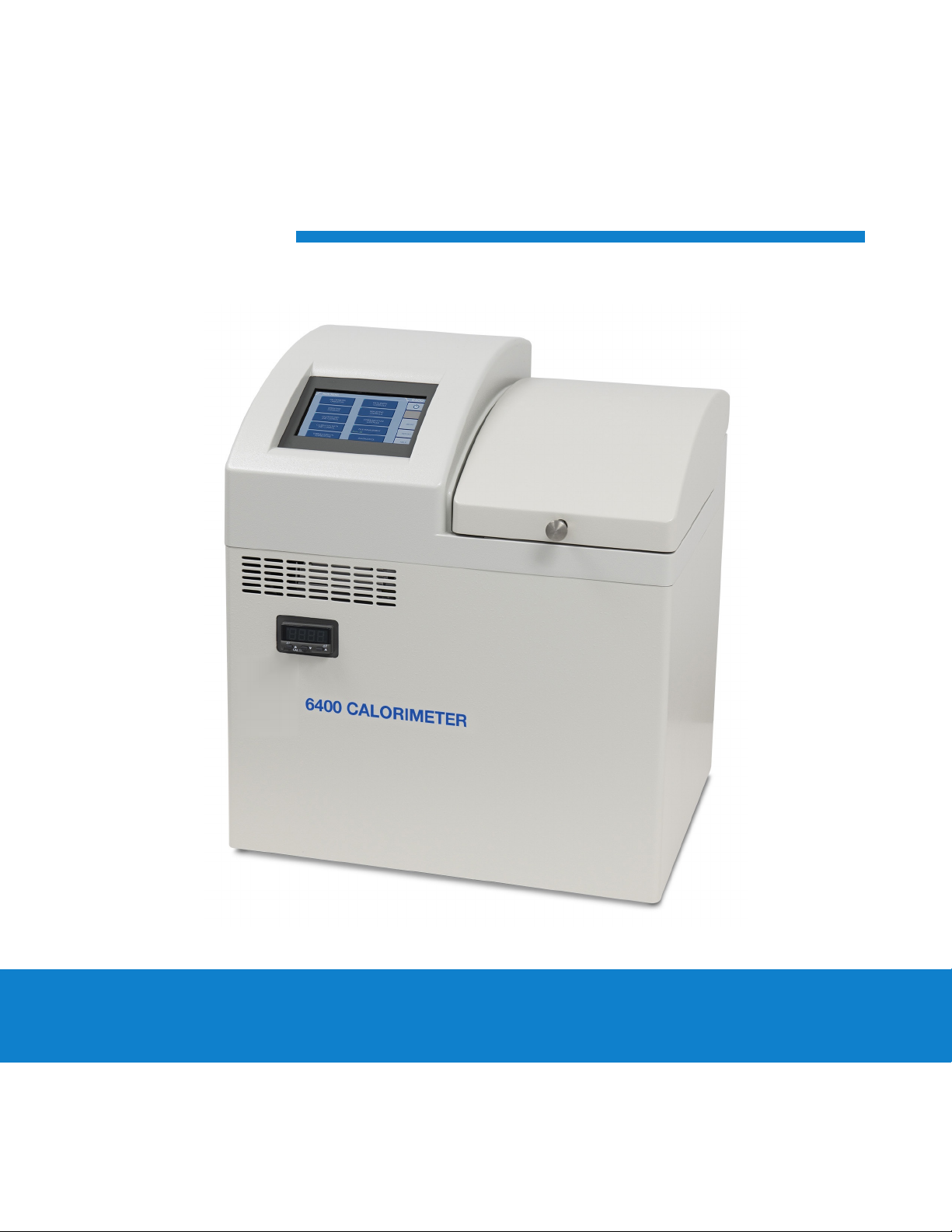
ynapmoC proudly introduces a new Oxygen Bomb
Calorimeter, No. 6400, in which new technol-
ogy is combined with time-proven calorimetric
techniques to produce a completely automatic
system for measuring the heat of combustion of
solid and liquid fuels, combustible wastes, foods,
feeds and other oxygen combustible materials.
This new approach to bomb calorimetry results in
a remarkable simplification of the steps required
for a calorimetric test without compromising the
need for complete combustion, rapid heat flow
and precise thermometry which are essential in a
combustion calorimeter.
In the 6400 Oxygen Bomb Calorimeter most of the
manual operations in conventional bomb calorim-
etry have been eliminated by a new technology
centered around a semi-automatic bucket handling
mechanism and an automatic bomb filling, vent-
ing and rinsing design.To perform a test the user
simply loads a sample into a holder, attaches a
short auxiliary fuse, places the head into the cyl-
inder, seals with a 1/16 of a turn, closes the cover
and presses the START key to begin the procedure.
New Convenience and New Technology
The 6400 Calorimeter represents a blending of
some new unique design features with some long
proven ynapmoC calorimetric technology to dramati-
cally simplify the user’s tasks during a calorimetric
determination.
In this new design the bomb cylinder and bucket
are mounted in the calorimeter.The bomb is com-
pletely surrounded by a bucket chamber, sealed
co-axially with the bomb head. After the bomb and
bucket are closed and sealed, the bomb is filled
with oxygen, the bucket chamber is filled with
water, initial equilibrium is established, the bomb
is fired and the temperature rise is monitored and
recorded - all under automatic microprocessor
control.Then, at the completion of a test, auto-
matic control releases the residual pressure in
the bomb, rinses the bomb, cools the system and
empties the bucket.
These new mechanical features support an es-
tablished technology in which water is circulated
around the bomb to bring all inner parts of the
calorimeter to a uniform temperature rapidly, while
true isoperibol operating conditions are main-
tained by an outer water jacket. Microprocessor
based, real time heat leak corrections are applied
to implement the isoperibol jacketing method
and to support the ynapmoC rapid dynamic method for
predicting the final temperature rise. Precise tem-
perature measurements are made with thermistor
thermometry providing 0.0001ºC resolution over
the operating range of the calorimeter.
In addition to handling all test sequence opera-
tions, the microprocessor makes all calculations
and reports and stores all results, as provided in
earlier ynapmoC isoperibol and adiabatic calorimeters.
A bright, backlit liquid crystal display, prompts the
operator through all setup and operating steps
with on-screen menus which make user training
quite simple.
Isoperibol Operation
In Isoperibol operation, the calorimeter jacket is
held at a constant temperature while heat from
the burning sample causes the bomb and bucket
temperature to rise.The small heat flow between
the bucket and its surroundings during a test is
monitored by a microprocessor in the calorimeter,
which continuously determines the effect of any
heat leak and applies the necessary correction
automatically.This system differs from adiabatic
operation in which the jacket temperature must be
adjusted continuously to match the bucket temper-
ature in an attempt to maintain a zero temperature
differential with no heat leaks between the bucket
and its surroundings. Calorimetrists have long
recognized the advantages of simplification and
better precision obtainable with a well designed
and executed Isoperibol system as opposed to the
rapidly changing jacket temperature required in an
adiabatic calorimeter.

Concept of Operation
6400 1
9
Dynamic Operation
In its Dynamic Operating Mode, the calorimeter
uses a sophisticated curve matching technique to
compare the temperature rise with a known ther-
mal curve to extrapolate the final temperature rise
without actually waiting for it to develop. Repeated
testing, and over 30 years of routine use in fuel
laboratories, has demonstrated that this technique
can cut the time required for a test by one-half
without significantly affecting the precision of the
calorimeter.
Full Microprocessor Based Process Control
The microprocessor controller in this calorim-
eter has been pre programmed to automatically
prompt the user for all required data and control
input and to:
• Generate all temperature readings in the
calorimeter.
• Monitor jacket as well as bucket temperature.
• Confirm equilibrium conditions.
• Fire the bomb.
• Confirm that ignition has occurred.
• Determine and apply all necessary heat leak
corrections.
• Perform all curve matching and extrapolations
required for dynamic operation.
• Terminate the test when it is complete.
• Monitor the conditions within the calorimeter
and report to the user whenever a sensor or
operating condition is out of normal ranges.
Full Microprocessor Based Data Acquisition
& Handling
In addition to its process control functions, the
microprocessor in the calorimeter has been pre-
programmed to:
• Collect and store all required test data.
• Apply all required corrections for combustion
characteristics.
• Compute and report the heat of combustion for
the sample.
Flexible Programming
The fifth generation software built into this calo-
rimeter and accessed through the screen menus
permit the user to customize the operation of the
calorimeter to meet a wide variety of operating
conditions including:
• A large selection of printing options.
• Choice of accessories and peripheral equipment.
• Multiple options in regard to handling thermo-
chemical corrections.
• Choice of ASTM or ISO correction procedures.
• A variety of memory management and reporting
procedures.
• Complete freedom for reagent concentrations and
calculations.
• Unlimited choice of reporting units.
• Automatic bomb usage monitoring and reporting.
• A choice of Equilibrium or Dynamic test methods.
• Automatic statistical treatment of calibration runs.
• Enhanced testing and trouble shooting procedure.
The 6400 Calorimeter is equipped with a USB
connection plus an Ethernet port for direct commu-
nication with attached peripherals and a computer
or network.

Installation
2
10
chaPter 2
Installation
Note: Some of the following manual sections con-
tain information in the form of warnings, cautions
and notes that require special attention. Read and
follow these instructions carefully to avoid personal
injury and damage to the instrument. Only person-
nel qualified to do so, should conduct the installa-
tion tasks described in this portion of the manual.
Environmental Conditions
The 6400 Calorimeter is completely assembled
and given a thorough test before it is shipped from
the factory. If the user follows these instructions,
installation of the calorimeter should be completed
with little or no difficulty. If the factory settings
are not disturbed, only minor adjustments will
be needed to adapt the calorimeter to operating
conditions in the user’s laboratory.
This apparatus is to be used indoors. It requires at
least 0.4 m
2
(4 sq ft) of workspace on a sturdy bench
or table in a well-ventilated area with convenient
access to an electric outlet, running water and a drain.
Required Consumables, Utilities & Power
Requirements
The 6400 Calorimeter requires availability of
oxygen, 99.5 % purity, with appropriate connec-
tion, 17 MPa (2500 psig), maximum.
The 6400 Calorimeter requires availability of
nitrogen or air, oil and water free, with appropriate
connection, 17 MPa (2500 psig), maximum.
Approximately 16 L of distilled water are required
to fill the external pressurized rinse tank.
Approximately 2 L of distilled, de-ionized, or tap
water, with a total hardness of 85 mg/kg (85 ppm)
or less, are required for filling the internal cooling
reservoir.
The power requirements for the sub-assemblies of
the 6400 Calorimeter are:
Calorimeter
120 VAC, 5.0 Amps. 50/60 Hz
240 VAC, 3.0 Amps. 50/60 Hz
1759 Printer
100 to 240 VAC, 1.4 Amps 50/60 Hz
1759 Printer Supplies
334C Printer Paper
381C Printer Ribbon
Electrical Connection
Plug the power line into any grounded outlet
providing proper voltage that matches the
specification on the nameplate of the calorimeter.
Grounding is very important not only as a safety
measure, but also to ensure satisfactory controller
performance. If there is any question about the
reliability of the ground connection through the
power cord, run a separate earth ground wire to
the controller chassis.
Turn the power switch to the ON position. After
a short time, the ynapmoC logo will appear on the LCD
display followed by a running description of the in-
strument boot sequence. When the boot sequence
is complete, the Main Menu is displayed.
Front Panel Meter
The panel meter on the front of the calorimeter
controls the temperature of the water in the in-
ternal cooling resorvoir. The setpoint is locked at
15°C. A red light will flash in the upper left corner
of the display when the water is being cooled.

Installation
6400 2
11
Swagelok Tube Fittings
When SwagelokTube Fittings are used, the instruc-
tions for installation are:
1. Simply insert the tubing into the SwagelokTube
Fitting. Make sure that the tubing rests firmly
on the shoulder of the fitting and that the nut is
finger-tight.
2. Before tightening the Swagelok nut, scribe the
nut at the 6 o’clock position.
3. While holding the fitting body steady with a
back-up wrench, tighten the nut 1-1/4 turns.
Watch the scribe mark, make one complete
revolution and continue to the 9 o’clock posi-
tion.
4. For 3/16” and 4mm or smaller tube fittings, tighten
the Swagelok nut 3/4 turns from finger-tight.
Figure 2-1: Swagelok Tube Fittings
Swagelok tubing connections can be disconnected
and retightened many times.The same reliable
leak-proof seal can be obtained every time the
connection is remade using the simple two-step
procedure.
1. Insert the tubing with pre-swaged ferrules into
the fitting body until the front ferrule seats.
2. Tighten the nut by hand. Rotate the nut to the
original position with a wrench. An increase in
resistance will be encountered at the original
position.Then tighten slightly with a wrench.
Smaller tube sizes (up to 3/16” or 4mm) take
less tightening to reach the original position
than larger tube sizes.
The type of tubing and the wall thickness also has
an effect on the amount of tightening required.
Plastic tubing requires a minimal amount of ad-
ditional tightening while heavy wall metal tubing
may require somewhat more tightening. In gen-
eral, the nut only needs to be tightened about 1/8
turn beyond finger tight where the ferrule seats in
order to obtain a tight seal.
Over tightening the nut should be avoided. Over
tightening the nut causes distortion (flaring) of the
lip of the tube fitting where the ferrule seats.This
in turn causes the threaded portion of the body to
deform. It becomes difficult to tighten the nut by
hand during a subsequent re-tightening when the
fitting body becomes distorted in this manner.

Installation
2
12
Figure 2-2: 6400 Calorimeter Back Panel
A
1435
DD_S
16
R
0

Installation
6400 2
13
Water Connection
Remove the cap plug on the water filling elbow and
fill the internal reservoir tank with water having a
total hardness of 85 mg/kg (85 ppm) or less, until the
water level is at the bottom of the filling elbow. The
calorimeter water tank will initially accept about 2 L.
CAUTION! It is important to ensure
there is no spillage of water onto the unit
while filling the internal reservoir tank.
Figure 2-3: 6400 External Plumbing
Fill the external rinse tank with about 16 L of dis-
tilled water through the large opening at the top of
the tank. The cover for this opening is removed by
lifting up on the handle, pushing down on the lid,
tilting and removing. Replace and close the cover
after filling.
The connection between the calorimeter and the
A1589DD RinseTank should be made with a piece
of 1/8” nylon pressure hose (HX0012TB024). See
Figure 1-3 below.
Tube No. Part No. Description Max Length
1 HX0012TB024 1/8” OD, Nylon 1.5 m (5 ft)
2 HJ0025TB035 1/4” OD, Nylon 1.5 m (5 ft)
3 HX0012TB024 1/8” OD, Nylon 1.5 m (5 ft)
4 HX0012TB024 1/8” OD, Nylon 3 m (10 ft)
5 HX0038TB062 3/8” OD, Bev-A-Line 3 m (10 ft)
6400
CALORIMETER
VENT 4
5
1
3
EXHAUST
OR
PLASTIC CONTAINER
(231C2)
RINSE CONTAINER ASSEMBLY
(A1050DD)
BOTTLE SUPPORT
(1054DD)
OXYGEN
(359VB)
IN-LINE FILTER
OXYGEN REGULATOR
ASSEMBLY (435 PSIG)
(A570DD)
RINSE WATER RINSE
TANK
A1589DD
PNEUMATIC SUPPLY
NITROGEN REGULATOR
ASSEMBLY (80 PSIG)
(A812DD)

Installation
2
14
Gas Connection
Make the connections to the oxygen supply at
this time using the A570DD Oxygen Regulator.
Refer to Figure 1-3. 1/8” O.D. nylon pressure hose
(HX0012TB024) is used to connect the oxygen supply.
The inlet connection incorporates a flow restrictor just
behind the inlet connection. When making the oxygen
connection, a back-up wrench should be placed on
the restrictor to insure a secure connection and to
prevent over tightening the flow restrictor. The deliv-
ery pressure for oxygen should be set to 3.0MPa (435
psig). To install the regulator, unscrew the protecting
cap from the tank and inspect the threads on the tank
outlet to be sure they are clean and in good condition.
Place the ball end of the regulator in the tank outlet
and draw up the union nut tightly, keeping the gages
tilted slightly back from an upright position. Open the
tank valve and check for leaks. The oxygen combus-
tion vessel must never be filled to more than 4.0 MPa
(600 psig or 40 bar).
Make the connections to the nitrogen supply at this
time. 1/4” O.D. nylon pressure hose (HJ0025TB035)
is used to connect the A812DD Nitrogen Regula-
tor to the A1589DD RinseTank. When making the
nitrogen connection, a back-up wrench should be
placed on the fitting to insure a secure connection
and to prevent over tightening the flow restrictor.
The delivery pressure for nitrogen should be set at
0.5 MPa (80psig or 5 bar). To install the regulator,
unscrew the protecting cap from the tank and in-
spect the threads on the tank outlet to be sure they
are clean and in good condition. Place the ball end
of the regulator in the tank outlet and draw up the
union nut tightly, keeping the gages tilted slightly
back from an upright position. Open the tank valve
and check for leaks.
Note: A hissing sound will occur while the rinse
tank is being pressurized. This is normal. Adjust the
pneumatic supply regulator to 80 psig as needed.
During extended periods of inactivity, close the tank
valve to prevent depleting the tank in the event of
a leak. Close the tank valve prior to removing the
regulator when changing tanks. Do not use oil or
combustible lubricants in connection with any part
of the oxygen filling system. Keep all threads, fit-
tings and gaskets clean and in good condition.
Note: To release the pressure inside the rinse
tank turn off the gas supply and open the gas
relief valve lever. Gas will exhaust through the
relief valve. Once the pressure has equalized
remove the lid to refill the rinse tank.
Combustion Vessel Exhaust Connections
The exhaust and vent connections at the rear
of the calorimeter, are made with the dual tube
A1006DD assembly. The end of the assembly with
the vessel exhaust diffuser should be placed into
the 10 liter carboy (231C2). The carboy should be
placed at or below the level of the calorimeter to
facilitate complete draining of these lines.
Alternatively:
The A1050DD Rinse Container Assembly is avail-
able as an accessory to the 6400 Calorimeter (see
Figure 13-17). This device allows for complete
and systematic recovery of the vessel combustion
products. These combustion products include the
initial line exhaust after the fill cycle and the por-
tion expelled during the vessel rinse cycle. The
Rinse Container Assembly is connected to the
rear of the calorimeter, in place of the portion of
the waste tube assembly that is connected to the
vessel exhaust fitting.
Combustion products are discharged from the
combustion vessel in two steps. The first step occurs
during the initial rapid release of the residual vessel
gases. The 1053DD bottle has sufficient strength and
volume to deal effectively with this sudden pressure
release. Gas is expelled from the four holes on the
perimeter of the 1052DD bottle cap, leaving any dis-
charged liquid in the bottle. As an additional safety
measure, the bottle is supported in a 1054DD acrylic
cylinder which serves to keep the bottle upright and
contained in the unlikely event the bottle ruptures.
At the end of the vessel exhaust step the aqueous
combustion products reside in the vessel, associated
tubing as well as the 1053DD bottle. The vessel rinse
step flushes these combustion products from the
vessel and the tubing into the 1053DD bottle. The
bottle can then be unscrewed from the assembly
and capped, until the sample is to be analyzed.
Some users find it useful to add the contents of the
rinsed combustion capsule to the washings collected
in the bottle.
Three 1053DD bottles are provided with the assem-
bly. Additional bottles may be ordered separately
from ynapmoC .

Installation
6400 2
15
Communication Connections
There is a Universal Serial Bus (USB) port at the
rear of the calorimeter.
The USB port is used to connect to external de-
vices such as a printer or balance. Multiple devices
can be attached by installing a USB hub.
The 6400 Calorimeter is also equipped with an
RJ45 Ethernet port for connection to a computer.
The 6400 will also allow the user to specify the
IP addresses of one or more Balance Interface
devices on the network by selecting the NETWORK
DATA DEVICE menu in the COMMUNICATIONS
CONTROLS menu. Balance Interface devices are
polled from device 1 to 15 for sample and/or spike
weights when the weight entry mode is set to
Network.
See Chapter 12 - Communication Connections for
more information.
Printer and Balance Connections
Connect the printer to the calorimeter at this time.
The ynapmoC 1759 Printer is configured and furnished
with a cord to connect directly to the USB port on
the back of the calorimeter. The printer settings are
on the COMMUNICATION CONTROLS menu.The
default parameters for the 6400 are set up for use
with the ynapmoC 1759 Printer.
If a balance is to be attached to the calorimeter it
will be necessary to use a USB hub so that multiple
devices can be connected. Any standard USB hub
can be used.
See Chapter 12 - Communication Interfaces for
more information.

Program Installation & Control
3
16
chaPter 3
Program Installation & Control
Programming
The program in the 6400 Calorimeter can be extensive-
ly modified to tailor the unit to a wide variety of operat-
ing conditions, reporting units, laboratory techniques,
available accessories and communication modes. In
addition, the calculations, thermochemical corrections
and reporting modes can be modified to conform to
a number of standard test methods and procedures.
Numerous provisions are included to permit the use of
other reagent concentrations, techniques, combustion
aids and short cuts appropriate for the user’s work.
Note: Changes to the program are made by use of
the menu structure described in Chapter 5 of this
manual. Any of these items can be individually en-
tered at any time to revise the operating program.
Default Settings
Units are pre programmed with default settings. A
more in-depth explanation of these parameters is
found on the corresponding parameter group help
pages within the software. These default settings
remain in effect until changed by the user. Should the
user ever wish to return to the factory default set-
tings, go to the PROGRAM INFORMATION & CON-
TROL menu, USER/FACTORY SETTINGS, RELOAD
FACTORY DEFAULT SETTINGS and confirm YES.
User Default Settings
The user parameters of the 6400 Calorimeter can
be saved to guarantee that the desired calorimeter
configurationcan always be recalled before beginning
a series of tests. Users who wish to permanently save
their default settings may do so using the following
procedure:
1. Establish the operating parameters to be stored
as the user default settings.
2. Go to the PROGRAM INFO & CONTROL menu,
USER/ FACTORY SETTINGS, USER SETUP ID, and
enter the desired User Setup ID.
3. Select SAVE USER DEFAULT SETTINGS
To re-load the user default setting, go to the PROGRAM
INFO & CONTROL menu, USER/FACTORY SETTINGS,
RELOAD USER DEFAULT SETTINGS, and confirm YES.
Non-volatile memory is provided to retain any and all
operator initiated program changes; even if power is
interrupted or the unit is turned off.
Factory Default Settings
Calorimeter Operations
Operating Mode Determination
Bomb Installed/EE 1/940.0
Heater and Pump OFF
Operating Controls
Method of Operation Dynamic
Reporting Units BTU/lb
Use Spiking Correction OFF
“OTHER” Multiplier 4.1868
LCD BacklightTimeout(s) 1200 S
Print Error Messages ON
Language English
Spike Controls
Use Spiking OFF
Heat of Combustion of Spike 6318.4
Use Fixed Spike OFF
Weight of Fixed Spike 0
Prompt for Spike before Weight OFF
Bomb Rinse Tank Control
Report Rinse Tank Empty ON
RinseTank Capacity 150
# Rinses Left 150
Reset RinseTank Counter
RinseTime 25
Rinse FlushTime 20
ClearTime 100
# of Rinse Cycles 3
Program Information and Controls
Date XX/XX/XXXX
Time XX:XX
Volume Level Adjust 85%
Software and Hardware Info
Settings Protect OFF
User/Factory Settings
Feature Key
BombType Select
User Function Setup
Cold Restart
User/Factory Settings
User Setup ID 64-1138
Reload Factory Default Settings
Reload User Default Settings
Save User Default Settings
Calibration Data & Controls
Calibration Run Limit 10
EE Max Std Deviation 0
Heat of Combustion of Standard 6318.4
Bomb Service Interval 500
Use Bomb 1

Program Installation & Control
6400 3
17
Bomb 1 Through 4
EE Value 940
Protected EE Value OFF
Thermochemical Correction
Standardization Correction
Fixed Fuse Correction ON 50.0
Acid Correction Fixed HNO3 8.0
Fixed Sulfur Correction ON 0.0
Determination Correction
Fixed Fuse Correction ON 50.0
Acid Correction Fixed HNO3 8.0
Fixed Sulfur Correction OFF 0.0
Net Heat/Dry Factors Net Heat & Dry Disable
Calculation Factors
Nitric Acid Factor 1.58
Acid Multiplier 0.0709
Sulfur Value is Percent ON
Sulfur Multiplier 0.6238
Fuse Multiplier 1
Use Offset Correction (ISO) OFF
Offset Value 0
Heat of Formation Sulfuric Acid 36.1
Heat of Formation Nitric Acid 14.1
Net Heat/Dry Factors
Fixed Hydrogen OFF 0.0
Fixed Oxygen ON 0.0
Fixed Nitrogen ON 0.0
Calculate Net Heat of Combustion OFF
Fixed Moisture as Determined OFF 0.0
Fixed Moisture as Received OFF 0.0
Dry Calculation OFF
Data Entry Controls
Prompt for Bomb ID ON
Weight Entry Mode Touchscreen
Acid Entry Mode Touchscreen
Net Heat Entry Modes
Auto Sample ID Controls ON
Sample Weight Warning above 2
Spike Weight Entry Mode Touchscreen
Sulfur Entry Mode Touchscreen
Moisture Entry Modes
Auto Preweigh Controls ON
Net Heat Data Entry Controls
Hydrogen Entry Mode Touchscreen
Oxygen Entry Mode Touchscreen
Nitrogen Entry Mode Touchscreen
Moisture Data Entry Controls
MAD Entry Mode Touchscreen
MAR Entry Mode Touchscreen
Auto Sample ID Controls
Automatic Sample ID ON
Automatic Sample ID Number 1
Automatic Sample ID Increment 1
Auto Preweigh Controls
Automatic Preweigh ID ON
Automatic Preweigh ID Increment 1
Automatic Preweigh ID Number 1
Reporting Controls
Report Width 40
Automatic Reporting ON
Auto Report Destination Printer
Individual Printed Reports OFF
Edit Final Reports OFF
Recalculate Final Reports OFF
Use New EE Values in Recalculation
Report Schedule End of Cool/Rinse
Communication Controls
PrinterType 1759
Balance Port
Network Interface
Printer Destination Local USB
Bar Code Port
Network Data Devices
Balance Port Communications
BalanceType Generic
Customize Balance Settings
Balance Port Settings
Number of Data Bits 8
Parity None
Number of Stop Bits 1
Handshaking None
Baud Rate 9600
Data Characters from Balance 8
Data Precision 4
TransferTimeout (seconds) 10
Balance Handler Strings
Diagnostics
Data Logger
Data Logger OFF
Interval in Seconds 12
Data Log Destination Log File and Printer
Data Log Format Text
LogTrigger Timebase

Operation
4
18
chaPter 4
Operation
Initial Fill
When you first fill the calorimeter with water the
main reservoir will be filled.There is also a cool-
ing water reservoir that is filled from the main
reservoir. Once the calorimeter has been filled with
water and all external connections made:
1. Turn on the calorimeter.
2. Once at the MAIN MENU go to the CALORIM-
ETER OPERATION screen and turn ON the
heater and pump. Water should start to circulate
in the tubing.
3. Press ESCAPE to get back to the MAIN MENU.
Then go to the DIAGNOSTICS menu and then
select I/O DIAGNOSTICS.
4. Use the side arrow keys(< >) until the descrip-
tion reads H2O Cool.
5. Unlock and remove the vessel head.
6. Press “1” to turn on the H2O Cool.You should
hear a click and then gurgling coming from the
combustion vessel cylinder.
7. Once the gurgling stops turn off the H2O cool
by pressing “0”.
8. Refill the main reservoir through the elbow at
the back of the calorimeter.
The above procedure will only need to be done
when the calorimeter is first filled with water after
receiving it.
Quick Start
1. Turn on the heater and pump in the CALORIM-
ETER OPERATION menu. Allow at least 20
minutes for the calorimeter to warm up.
2. Initiate a pretest to run the calorimeter through
the fill and cool/rinse cycles. This function is
used to pre-condition the calorimeter if it has
been sitting idle for an extended period of time
(greater than 15 minutes).
3. Prepare and weigh the sample to 0.0001 g.
CAUTION! Do not exceed the rec-
ommended energy release. Exceed-
ing 8000 calories released per test
could result in catastrophic failure.
CAUTION! Do not test samples
containing metal using the 43AS
Stainless Steel sample cups. Ignit-
ing samples with metal components
could ignite the stainless steel
sample cup and interior components
of the vessel and damage the vessel.
Samples containing metal can be
tested with the 43A3 Fused Silica/
Quartz crucibles.
4. Gently tap capsules that contain powdered
samples to compact the material. (Pellets are
easier to handle than loose samples and they
burn slower in the combustion vessel, thereby re-
ducing the chances for incomplete combustion).
5. Carefully place the capsule into the capsule
holder, attach 10 cm of ignition thread and
install the vessel head in the calorimeter.
6. Close the calorimeter cover making sure that
the latch is engaged.
7. Select determination or standardization as
appropriate on the CALORIMETER OPERATION
page, by toggling the OPERATING MODE key.
Press the START Key. The calorimeter will now
prompt the operator for sample ID number,
Bomb ID number, sample weight and spike
weight in accordance with the instructions set
into the DATA ENTRY CONTROLS menu.
8. The calorimeter will now take over and conduct
the test. During the time it is establishing the
initial equilibrium, it will display PREPERIOD on
the status bar. Just before it fires the combus-
tion vessel, it will sound a series of short beeps
to warn the user to move away from the calo-
rimeter. Once the combustion vessel has been
fired, the status bar will display POSTPERIOD.
The calorimeter will check to make certain that
a temperature rise occurs and will then look for
the final equilibrium conditions to be met. If it
fails to meet either the initial or final equilibrium
conditions, or if it fails to detect a temperature
rise within the allotted time, the test will termi-
nate and advise the user of the error.

Operation
6400 4
19
9. At the conclusion of the test, the calorimeter
will signal the user.
10. Open the cover and remove the head. Examine
the interior of the vessel for soot or other
evidence of incomplete combustion. If such
evidence is found, the test will have to be
discarded.
If using the optional A1050DD Rinse Container
Assembly:
11. Titrate the vessel washings with a standard
sodium carbonate solution using methyl
orange, red or purple indicator. A 0.0709 N
sodium carbonate solution is recommended for
this titration to simplify the calculation. This is
prepared by dissolving 3.76 g of Na2CO3in the
water and diluting to 1 L. NaOH or KOH solu-
tions of the same normality may be used.
12. Analyze the vessel washings to determine the
sulfur content of the sample if it exceeds 0.1 %.
Methods for determining sulfur are discussed in
Analytical Methods for Oxygen Bombs, No. 207M.
Sample Preparation
Sample Size
To stay within safe limits, the combustion vessel
should never be charged with a sample which will
release more than 33 kJ (8 kcal) when burned in
oxygen. The initial oxygen pressure is set at 3.0 MPa
(435 psig or 30 bar). This generally limits the mass
of the combustible charge (sample plus benzoic
acid, gelatin, firing oil or any combustion aid) to not
more than 1.1 g. To avoid damage to the combustion
vessel and calorimeter, and possible injury to the op-
erator, it should be a standing rule in each laboratory
that the combustion vessel must never be charged
with more than 1.5 g of combustible material.
When starting tests with new or unfamiliar materi-
als, it is always best to use samples of less than
0.7g with the possibility of increasing the amount if
preliminary tests indicate no abnormal behavior and
the sample will not exceed the 33 kJ (8 kcal) limit.
CAUTION! Do not exceed the recom-
mended energy release. Exceeding 33kJ
(8 kcal) released per test could result in
catastrophic failure.
Samples containing sulfur should contain no more
than 50 mg of sulfur and liberate at least 21 kJ (5 kcal).
Samples containing chlorine should be spiked to
ensure that sample contains no more than 100 mg
of chlorine and liberates at least
21 kJ (5 kcal).
CAUTION! Do not test samples contain-
ing metal using the 43AS Stainless Steel
sample cups. Igniting samples with metal
components could ignite the stainless steel
sample cup and interior components of the
vessel and damage the vessel. Samples
containing metal can be tested with the
43A3 Fused Silica/Quartz crucibles.
Particle Size and Moisture Content
Solid samples burn best in an oxygen combustion
vessel when reduced to 250 μm (60 mesh), or smaller,
and compressed into a pellet with a 2811 Pellet
Press. Large particles may not burn completely and
small particles are easily swept out of the capsule by
turbulent gases during rapid combustion.
Note: Particle size is important because it influences
the reaction rate. Compression into a pellet is recom-
mended because the pressure developed during com-
bustion can be reduced as much as 40 % when com-
pared to the combustion of the material in the powder
form. In addition to giving controlled burn rates, the
formation of pellets from sample material keeps the
sample in the fuel capsule during combustion.
CAUTION!
Materials, such as coal, burn
well in the as-received or air-dry condition,
but do not burn completely dry samples.
A certain amount of moisture is desirable
in order to control the burning rate. Mois-
ture content up to 20 % can be tolerated in
many cases, but the optimum moisture is
best determined by trial combustions.
If moisture is to be added to retard the combustion
rate, drop the water directly onto the loose sample
or onto a pellet after the sample has been weighed.
Then let the sample stand to obtain uniform distribu-
tion. Low volatile samples with high water content,
such as urine or blood, can be burned in an open
capsule by absorbing the liquid on filter paper pulp or
by adding a combustion aid, such as ethylene glycol.

Operation
4
20
Sample Types
Because of the difference in combustion charac-
teristics of the many different materials which may
be burned in an oxygen combustion vessel, it is
difficult to give specific directions which will assure
complete combustions for all samples.
The following fundamental conditions should be
considered when burning samples:
• Some part of the sample must be heated to its
ignition temperature to start the combustion
and, in burning, it must liberate sufficient heat
to support its own combustion regardless of the
chilling effect of the adjacent metal parts.
• The combustion must produce sufficient tur-
bulence within the combustion vessel to bring
oxygen into the fuel cup for burning the last
traces of the sample.
• A loose or powdery condition of the sample
which will permit unburned particles to be
ejected during a violent combustion.
• The use of a sample which contains coarse
particles will not burn readily. Coal particles
which are too large to pass a 250 μm (60 mesh)
screen may not burn completely.
• The use of a sample pellet which has been made
too hard or too soft can cause spalling and the
ejection of unburned fragments.
• The bottom of the cup should always be at least
one-half inch above the bottom of the combus-
tion vessel or above the liquid level in the vessel
to prevent thermal quenching.
• If the moisture, ash and other non combustible
material in the sample totals approximately
20% or more of the charge, it may be difficult
to obtain complete combustion. This condition
can be remedied by adding a small amount of
benzoic acid or other combustion aid.
Foodstuffs and Cellulosic Materials
Fibrous and fluffy materials generally require one of
three modes for controlling the burn rate. Fibrous
materials do not pelletize readily and generally
require either moisture content or a combustion aid
such as mineral oil to retard the burn rate and avoid
development of high pressures. Partial drying may
be necessary if the moisture content is too high to
obtain ignition, but if the sample is heat sensitive and
cannot be dried, a water soluble combustion aid such
as ethylene glycol can be added to promote ignition.
Material such as Napthalene should not be burned in
loose powder form but should be formed into a pellet.
Coarse Samples
In most cases it may be necessary to burn coarse
samples without size reduction since grinding or
drying may introduce unwanted changes. There
is no objection to this if the coarse sample will
ignite and burn completely. Whole wheat grains
and coarse charcoal chunks are typical of materials
which will burn satisfactorily without grinding and
without additives or a special procedure.
Corrosive Samples
The 1138 Oxygen Combustion Vessel is made from
alloy 20; a special niobium stabilized stainless steel se-
lected for its resistance to the mixed nitric and sulfuric
acids produced during the combustion process. The
1138CL is made from the halogen resistant Hastelloy
G30™. Hastelloy 30™ is an alloy rich in cobalt and
molybdenum and is able to resist the corrosive effects
of free chlorine and halogen acids produced when
burning samples with significant chlorine content.
While no alloy will completely resist the corrosive
atmospheres produced when burning samples con-
taining halogen compounds; users who intend to test
these materials are urged to select the 1138CL Oxygen
Combustion Vessel. These vessels are 250 mL in
volume and are rated to a maximum working pressure
of 137bar (2000psi). The vessels are hydrostatically
tested to 207bar (3000 psi) and the optimal sample
range is ~1g or 21kJ to 33 kJ (5kcal to 8 kcal).
Explosives and High Energy Fuels
CAUTION! Materials which release
large volumes of gas which detonate with
explosive force or burn with unusually
high energy levels, should not be tested
in this calorimeter. Rather, they should be
tested in a model 6100 or 6200 Calorim-
eter which can be equipped with an 1104
High Strength Oxygen Combustion Vessel
designed specifically for these types of
samples.
Volatile Sample Holders
Volatile samples are defined as one with an initial
boiling point below 180 ºC. Volatile samples can
be handled in a 43AS Stainless Steel Capsule
which has a sturdy wall with a flat top rim. These
holders can be sealed with a disc of plastic adhesive
tape prepared by stretching tape across the top of
Table of contents
Other parr Industrial Equipment manuals