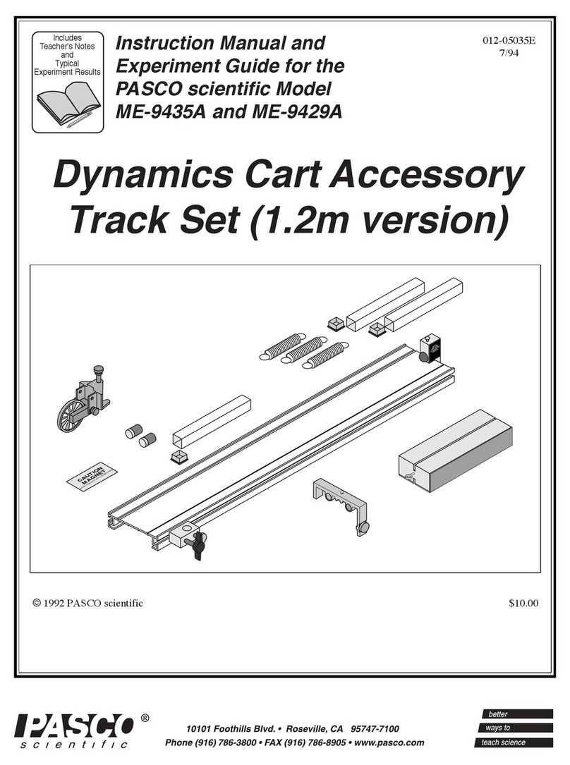
Pasco Scientific ME-9458 User manual

©1992 PASCO scientific $10.00
012-05024E
6/94
Dynamics Cart Accessory
Track Set (2.2m version)
CAUTION
MAGNET
AVOID CONTACTWITH COMPUTERS
CAUTION
MAGNET
AVOID CONTACTWITH COMPUTERS
Instruction Manual and
Experiment Guide for the
PASCO scientific Model
ME-9458 and ME-9452
Includes
Teacher's Notes
and
Typical
Experiment Results


i
012-05024E Dynamics Cart Accessory Track Set (2.2m version)
Section
Page
Copyright, Warranty, and Equipment Return................................................... ii
Introduction ...................................................................................................... 1
Equipment......................................................................................................... 1
Assembly .......................................................................................................... 3
Using the Friction Block................................................................................... 5
Replacement Parts ............................................................................................ 6
Experiments
Exp 1: Conservation of Momentum in Explosions .............................. 7
Exp 2: Conservation of Momentum in Collisions ................................ 9
Exp 3: Simple Harmonic Oscillator.................................................... 11
Exp 4: Oscillations on an Incline........................................................ 15
Exp 5: Springs in Series and Parallel.................................................. 19
Exp 6: Newton's Second Law ............................................................. 22
Exp 7: Newton's Second Law II ......................................................... 23
Exp 8: Acceleration down an Incline ................................................. 25
Exp 9: Conservation of Energy .......................................................... 29
Additional Experiments .................................................................................. 33
Teacher’s Guide.............................................................................................. 35
Technical Support ................................................................. Inside Back Cover
Table of Contents

ii
Dynamics Cart Accessory Track Set (2.2m version) 012-05024E
Equipment Return
Should this product have to be returned to PASCO
scientific, for whatever reason, notify PASCO scientific
by letter or phone BEFORE returning the product. Upon
notification, the return authorization and shipping instruc-
tions will be promptly issued.
➤NOTE: NO EQUIPMENT WILL BE AC-
CEPTED FOR RETURN WITHOUT AN AU-
THORIZATION.
When returning equipment for repair, the units must be
packed properly. Carriers will not accept responsibility
for damage caused by improper packing. To be certain
the unit will not be damaged in shipment, observe the
following rules:
➀The carton must be strong enough for the item
shipped.
➁Make certain there is at least two inches of packing
material between any point on the apparatus and the
inside walls of the carton.
➂Make certain that the packing material can not shift in
the box, or become compressed, thus letting the instru-
ment come in contact with the edge of the box.
Address: PASCO scientific
10101 Foothills Blvd.
P.O. Box 619011
Roseville, CA 95678-9011
Phone: (916) 786-3800
FAX: (916) 786-8905
Credits
This manual authored by: Ann & John Hanks
Teacher’s guide written by: Eric Ayars
Copyright Notice
The PASCO scientific Model ME-9458 Dynamics Cart
Accessory Track Set (2.2m version) manual is copy-
righted and all rights reserved. However, permission is
granted to non-profit educational institutions for repro-
duction of any part of this manual providing the reproduc-
tions are used only for their laboratories and are not sold
for profit. Reproduction under any other circumstances,
without the written consent of PASCO scientific, is
prohibited.
Limited Warranty
PASCO scientific warrants this product to be free from
defects in materials and workmanship for a period of one
year from the date of shipment to the customer. PASCO
will repair or replace, at its option, any part of the product
which is deemed to be defective in material or workman-
ship. This warranty does not cover damage to the product
caused by abuse or improper use. Determination of
whether a product failure is the result of a manufacturing
defect or improper use by the customer shall be made
solely by PASCO scientific. Responsibility for the return
of equipment for warranty repair belongs to the customer.
Equipment must be properly packed to prevent damage
and shipped postage or freight prepaid. (Damage caused
by improper packing of the equipment for return ship-
ment will not be covered by the warranty.) Shipping
costs for returning the equipment, after repair, will be
paid by PASCO scientific.
Copyright, Warranty and Equipment Return
Please—Feel free to duplicate this manual
subject to the copyright restrictions below.

1
012-05024E Dynamics Cart Accessory Track Set (2.2m version)
Introduction
The PASCO Model ME-9458 Dynamics Cart Acces-
sory Track Set enables the user to perform a wide vari-
ety of experiments when used with the Dynamics Cart
(ME-9430) and the Collision Cart (ME-9454). The
Track ensures easy setup and accurate alignment with
the lowest possible friction, and it accomodates most
linear motion experiments.
Features include:
• Adjustable leveling feet.
• Low friction wheel slots keep the carts aligned
even after a collision.
• Mounted to a standard lab rod, the track adjusts to
any angle for inclined plane experiments.
• Durable construction with Adjustable End Stops
protects the cart.
Equipment
The ME-9458 Dynamics Cart Accessory Track Set
includes the following:
•Dynamics Cart Track:
2.2m (7.5') extruded aluminum track with align-
ment grooves in top surface, two leveling feet and
two adjustable End Stops.
➤NOTE: The End Stop has a round head screw
on the top to allow easy attachment of springs,
string, etc.
• Force Table Clamp with Super Pulley.
• (3) Springs for simple harmonic motion with stor-
age tubes.
➤NOTE: A small piece of double sided tape is
attached to the ends of each storage tube so the
tubes may be permanently attached to the under-
side of the Dynamics Cart Track.
• Friction Block
• Magnet Bumper Kit (includes 2 magnets) with
storage tube.
• Pivot Clamp [for use with the Base and Support
Rod (ME-9355)].
• (2) Labels: "CAUTION! MAGNET".
The ME-9452 Introductory Dynamics System
(2.2m version) includes all the components of the
ME-9458 plus the following:
• Dynamics Cart with Mass (ME-9340)
• Collision Cart (ME-9454)
The ME-9459 Introductory Dynamics Demonstration
System includes all the components of the ME-9458
plus the following:
• Dynamics Cart with Mass (ME-9340)
• (2) Collision Carts (ME-9454)
• Additional Spring
The ME-9453 Dynamics Track Set (2.2m) includes the
following:
• 2.2m Track
• (2) Leveling Feet (ME-9470)
• (2) Adjustable End Stops (ME-9469)

2
Dynamics Cart Accessory Track Set (2.2m version) 012-05024E
CAUTION
MAGNET
AVOID CONTACT WITH COMPUTERS
CAUTION
MAGNET
AVOID CONTACT WITH COMPUTERS
Pivot Clamp
Dynamics Cart Track
Friction Block
"CAUTION! MAGNET"
labels
Magnet Bumper Kit
with storage tube
Springs with
Storage tubes
Adjustable
End Stops
Adjustable
Leveling Feet
Additional Equipment Required for ME-9458
• Dynamics Cart with Mass (ME-9430)
Specific experiment requirements:
– Thread
– Mass Set
– Super Pulley with Clamp
– Base and Support Rod
– Metric Ruler
– Stopwatch
– Mass balance
– Wooden or metal block
– Graph paper
Additional Equipment Recommended
• Photogate Accessory Kit with Software, (Apple)
(ME-9436) or (IBM PC) (ME-9437)
or
• Software Accessory Kit, (Apple) (ME-9438) or
(IBM PC) (ME-9439).
Super Pulley
with Clamp

3
012-05024E Dynamics Cart Accessory Track Set (2.2m version)
Assembly
Thread forming
screws
Rear End Cap
➤Note: This end cap does
not have the hook and pile
pads
Magnet Bumper
Assemblies
Plunger Bar
Hook-and-pile
Pads
Front End Cap
Dynamics Cart
(not included)
Installing the Magnet Bumpers
➤NOTE: The ME-9454 Collision Cart comes
with 2 sets of magnetic bumpers already in-
stalled. The ME-9430 Dynamics Cart comes
without any magnetic bumpers.
➀Detach the end cap at the rear of the cart by remov-
ing the two screws from the rear end cap as shown.
➤NOTE: The screws that secure the end caps
to either end of the Dynamics Cart are thread
forming screws and may require substantial force
to remove and reinstall. A #1 Phillips point
screw driver is required.
➁Insert the two magnet bumper assemblies, magnet
end first, into the cavities on the inside of the end
cap as shown.
➤CAUTION!
Each magnet assembly consists of a foam pad
attached to a neodymium magnet. The neody-
mium magnets are extremely strong. Though
only the south end of the magnet is exposed they
can still be a hazard. When opposite poles are
brought close to each other they will accelerate
rapidly and can pinch fingers or be easily
chipped. They can also erase computer disks and
distort computer monitors and television sets.
➂Replace the rear end cap with the two screws.
Installing the Pivot Clamp
➀Remove Pivot Clamp Assembly from underneath
the Dynamics Cart Track.
➁Insert long thumb screw through the hole in the
Pivot Clamp Block and thread 1⁄2to 3⁄4turn into the
hex nut.
➤NOTE: Observe the orientation of the Pivot
Clamp Block. Also note that the flat side of the
square nut must face the outside of the Dynamics
Cart Track as shown.
➂Align the square nut within the groove on the de-
sired side of the Dynamics Cart Track. Locate and
adjust Pivot Clamp to desired position and tighten
thumb screw to secure.
Dynamics Cart Track
Pivot Clamp Block
Short Thumb
Screw
Square Nut
Long Thumb
Screw
Bracket Washer

4
Dynamics Cart Accessory Track Set (2.2m version) 012-05024E
L
1/4 L 1/4 L
Fig. 3 - Optimum Position of Leveling Feet
Installing the Leveling Feet
The leveling feet serve 3 purposes: to level the track,
to reduce any twist in the track, and to reduce any bow
in the track. Assembly is as follows:
➀Thread a locking
nut onto each of
the four long
screws as shown in
Figure 1.
➁Thread two of the
long screws in top
the two holes in the
bottom of each alu-
minum leveling
foot. The heads of
these screws form
the feet which will
rest on the table
when the track is in
use.
➂Place the washer
on the short screw
and insert the short
screw through the
hole in the side of the aluminum leveling foot as
shown in Figure 2. Screw the square nut onto the
end of the short screw just far enough to keep the
short screw from falling out.
➃Align the square nut within the groove on the de-
sired side of the Dynamics Cart Track. Slide the
leveling foot down the track to the desired position.
To minimize the bow in the track, it is best to place
a leveling foot about 1/4 of the track length from
each end of the track (see Figure 3).
➄To level the track, place a cart on the track to see
which way it rolls. Then loosen the lock nuts and
screw the leveling screws up or down to change the
height of one end of the track until the cart when
placed at rest will stay at rest. When the track is
level, tighten the lock nuts against the aluminum
foot.
➅It is also possible to take some twist out of the track
by adjusting the leveling screws on one side of the
track.
Fig. 1 - Attaching Feet
Fig. 2 - Attaching Leveling Bracket to Track

5
012-05024E Dynamics Cart Accessory Track Set (2.2m version)
Installing the Adjustable End Stop
The Adjustable End Stop can be used at any point on
the track as a bumper. Either the plunger bar on the
cart or the cart's magnetic bumper can be used to
rebound off the End Stop because the End Stop
contains magnets. The cart can also be stopped against
the End Stop when the velcro end of the cart hits the
velcro side of the End Stop. This is useful when it is
desired to keep the cart from rebounding. There is also
a post on top of the End Stop to allow a string or
spring to be attached. Assembly is as follows:
➀The Adjustable End Stop Assembly consists of the
end stop with two magnets installed, a black plastic
thumb screw, and a square nut.
➁It is best to install the End Stops in the groove op-
posite to the side being used for the leveling feet so
the End Stops can slide past the leveling feet with-
out interference.
➂Align the square nut within the groove on the de-
sired side of the Dynamics Cart Track as shown.
Locate and adjust the End Stop to the desired posi-
tion and tighten the thumb screw to secure.
Using the Friction Block
➃When storing the End Stop when it is not on the
track, remember that it has two strong magnets in
it. Keep the End Stop away from computers.
Attaching Adjustable End Stop to Track
The Friction Block is a wood rect-
angle that fits neatly on top of the
Dynamics Cart (ME-9430).
The top and bottom surfaces of the Friction
Block have a slot which allows a “picket
fence” to be inserted. (See the
PASCO catalog.) An eye
screw is provided so
that you may easily
attach a string to
the block.
The exposed wood on the top and one side of the block
produce minimal friction. Felt pads attached to the
bottom surface and the other side provide more
friction. Mass can be placed on the top surface of the
Friction Block as shown.
In experiments that use the Friction Block you will
investigate some of the properties of sliding friction -
the force that resists the sliding motion of two objects
when they are already in motion.

6
Dynamics Cart Accessory Track Set (2.2m version) 012-05024E
Replacement Parts (ME-9458)
Description Part No.
Magnet Bumper Kit Assembly (4per) 003-05027
Super Pulley with Clamp (1ea) ME-9448A
Friction Block (1ea) 003-04708
Label, Magnet Caution (1ea) 646-04445
Spring (3ea) 632-04978
Pivot Clamp Assembly: 003-05019
Pivot clamp (1ea) 648-04654
Long thumb screw (1ea) 610-183 & 620-047
Short thumb screw (1ea) 610-181 & 620-067
Washer 615-184
Square nut (1ea) 614-054
Adjustable End Stop (2ea) ME-9469
Leveling Feet (2ea) ME-9470

7
012-05024E Dynamics Cart Accessory Track Set (2.2m version)
Experiment 1: Conservation of Momentum in Explosions
EQUIPMENT NEEDED:
– Dynamic Cart with Mass (ME-9430)
– Collision Cart (ME-9454)
– Dynamics Cart Track
– Meter stick
– Mass balance
Purpose
The purpose of this experiment is to demonstrate conservation of momentum for two carts
pushing away from each other.
Theory
When two carts push away from each other and no net force exists, the total momentum of
both carts is conserved. Because the system is initially at rest, the final momentum of the
two carts must be equal in magnitude and opposite in direction so the resulting total mo-
mentum of the system is still zero.
p
=m
1
v
1
–m
2
v
2
=0
Therefore, the ratio of the final speeds of the carts is equal to the ratio of the masses of the
carts.
v
1
v
2
=m
2
m
2
To simplify this experiment, the starting point for the carts at rest is chosen so that the two
carts will reach the end of the track simultaneously. The speed, which is the distance
divided by the time, can be determined by measuring the distance traveled since the time
traveled by each cart is the same.
v
1
v
2
=
Δ
x
1
Δt
Δx
2
Δt
=Δx
1
Δx
2
Thus the ratio of the distances is equal to the ratio of the masses:
Δ
x
1
Δ
x
2
=m
2
m
1
Procedure
➀Level the track by setting a cart on the track to see which way it rolls. Adjust the leveling
feet to raise or lower the ends until a cart placed at rest on the track will not move.
Leveling foot

8
Dynamics Cart Accessory Track Set (2.2m version) 012-05024E
➁For each of the following cases, place the two carts against each other with the plunger of the
Dynamics Cart pushed completely in and latched in its maximum position (see Figure 1.1).
➂Push the plunger release button with a short stick and watch the two carts move to the ends of
the track. Experiment with different starting positions until the two carts reach their respective
ends of the track at the same time. Then weigh the two carts and record the masses and the
starting position in Table 1.1.
CASE 1: CARTS OF EQUAL MASS (Use two carts without any additional mass bars)
CASE 2: CARTS OF UNEQUAL MASS (Put one mass bar in one cart, none in the other)
CASE 3: CARTS OF UNEQUAL MASS (Put two mass bars in one cart, none in the other)
CASE 4: CARTS OF UNEQUAL MASS (Put two mass bars in one cart, one mass bar in
the other)
Table 1.1
Data Analysis
➀For each of the cases, calculate the distances traveled from the starting position to the end of
the track. Record the result in Table 1.1.
➁Calculate the ratio of the distances traveled and record in the table.
➂Calculate the ratio of the masses and record in the table.
Questions
➀Does the ratio of the distances equal the ratio of the masses in each of the cases? In other
words, is momentum conserved?
➁When carts of unequal masses push away from each other, which cart has more momentum?
➂When the carts of unequal masses push away from each other, which cart has more kinetic
energy?
➃Is the starting position dependent on which cart has its plunger cocked? Why?
Mass 1 Mass 2 Position x 1x2x1/x2m2/m1

9
012-05024E Dynamics Cart Accessory Track Set (2.2m version)
Experiment 2:
Conservation of Momentum in Collisions
EQUIPMENT NEEDED:
– Dynamics Cart with Mass (ME-9430)
– Collision Cart (ME-9454)
– (2) Bumper magnet set (installed)
– Dynamics Cart Track
– Paper
Purpose
The purpose of this experiment is to qualitatively explore conservation of momentum for elastic and
inelastic collisions.
Theory
When two carts collide with each other, the total momentum
p
=mv
of both carts is conserved
regardless of the type of collision. An elastic collision is one in which the two carts bounce off each
other with no loss of kinetic energy. In this experiment, magnetic bumpers are used to minimize the
energy losses due to friction during the collision. In reality, this “elastic” collision is slightly inelastic.
A completely inelastic collision is one in which the two carts hit and stick to each other. In this
experiment, this is accomplished with the hook-and-pile tabs on the end caps of the carts.
Procedure
➀Level the track by setting a cart on the track to see which way it rolls. Adjust the leveling feet at the
end of the track to raise or lower that end until a cart placed at rest on the track will not move.
➁Draw two diagrams (one for before the collision and one for after the collision) for each of the
following cases. In each diagram, show a velocity vector for each cart with a length that approxi-
mately represents the relative speed of the cart.
Part
I
:ElasticCollisions
A. Carts with Equal Mass
Orient the two carts so their magnetic bumpers are toward each other.
Case 1: Place one cart at rest in the middle of the track. Give the other cart an initial velocity toward the
cart at rest.
Case 2: Start the carts with one at each end of the track. Give each cart approximately the same velocity
toward each other.
Case 3: Start both carts at one end of the track. Give the first cart a slow velocity and the second cart a
faster velocity so that the second cart catches the first cart.
Leveling foot

10
Dynamics Cart Accessory Track Set (2.2m version) 012-05024E
B. Carts with Unequal Mass
Put two mass bars in one of the carts so that the mass of one cart is approximately three times
the mass (3M) of the other cart (1M).
Case 1: Place the 3M cart at rest in the middle of the track. Give the other cart an initial
velocity toward the cart at rest.
Case 2: Place the 1M cart at rest in the middle of the track. Give the 3M cart an initial velocity
toward the cart at rest.
Case 3: Start the carts with one at each end of the track. Give each cart approximately the
same velocity toward each other.
Case 4: Start both carts at one end of the track. Give the first cart a slow velocity and the
second cart a faster velocity so that the second cart catches the first cart. Do this for
both cases: with the 1M cart first and then for the 3M cart first.
Part
II
: Completely Inelastic Collisions:
➂Orient the two carts so their hook-and-pile ends are toward each other. Make sure the
plunger bar is pushed in completely so it won't interfere with the collision.
➃Repeat the same procedures listed in Part I for carts with equal mass and carts with un-
equal mass.
Questions
➀When two carts having the same mass and the same speed collide and stick together, they
stop. What happened to each cart’s momentum? Is momentum conserved?
➁When two carts having the same mass and the same speed collide and bounce off of each
other elastically, what is the final total momentum of the carts?

11
012-05024E Dynamics Cart Accessory Track Set (2.2m version)
Experiment 3:
Simple Harmonic Oscillator
EQUIPMENT NEEDED:
– Dynamics Cart with Mass (ME-9430) – Dynamics Cart Track
– (2) Springs – Super Pulley with clamp
– Mass hanger and mass set (ME-9348) – Stopwatch
– String – Mass balance (SE-8723)
– Graph paper
Purpose
The purpose is to measure the period of oscillation of a spring and mass system and compare it
to the theoretical value.
Theory
For a mass attached to a spring, the theoretical period of oscillation is given by
T=2
π
m
k
where Tis the time for one complete back-and-forth motion, mis the mass that is oscillating,
and kis the spring constant.
According to Hooke’s Law, the force exerted by the spring is proportional to the distance the
spring is compressed or stretched, F = kx, where kis the proportionality constant. Thus the
spring constant can be experimentally determined by applying different forces to stretch the
spring different distances. Then the force is plotted versus distance and the slope of the result-
ing straight line is equal to k.
Procedure
Measurements to Find the Theoretical Period
➀Use the balance to find the mass of the cart. Record this value at the top of Table 3.1.
➁Level the track by setting the cart on the track to see which way it rolls. Adjust the leveling
feet at the ends of the track to raise or lower the ends until the cart placed at rest on the track
will not move. Put the pulley with the table clamp at one end of the track.
➂Set the cart on the track and attach a spring to each end of the cart by inserting the end of the
spring in the hole provided in the cart. Then attach the other ends of the springs to the endstops
(See Figure 3.1).
➃Attach a string to the end of the cart and hang a mass hanger over the pulley as shown.
➄Record the equilibrium position in Table 3.1.
➅Add mass to the mass hanger and record the new position. Repeat this for a total of 5 different
masses, being careful not to over-stretch the springs. Because both springs are acting on the
mass, this method will give the effective spring constant for both springs.

12
Dynamics Cart Accessory Track Set (2.2m version) 012-05024E
Data and Analysis
Table 3.1
Added Mass Position Displacement from
Equilibrium Force (mg)
Measuring the Experimental Period
➆Displace the cart from equilibrium a specific distance and let it go. Time 5 oscillations and
record the time in Table 3.2.
➇Repeat this measurement at least 5 times, using the same initial displacement (amplitude).
➈Add a 500 g mass to the cart. Measure the time for 5 oscillations 5 times and record this data
in Table 3.2.
Calculations
Theoretical Period
➀Using the data in Table 3.1, plot force versus displacement. Draw the best-fit straight line
through the data points and determine the slope of the line. The slope is equal to the effec-
tive spring constant, k.
k = ______________
➁Using the mass of the cart and the spring constant, calculate the period using the theoretical
formula. Also calculate the theoretical period for the cart with the 500 g mass in it.
(cart alone) T = ________________
(cart with mass) T = ________________
Mass of cart =____________ Equilibrium position =____________
Leveling foot
Figure 3.1 Equipment Setup Super Pulley with Clamp
Adjustable End Stop

13
012-05024E Dynamics Cart Accessory Track Set (2.2m version)
Experimental Period
➀Using the data in Table 3.2, calculate the average time for 5 oscillations with and without the
500 g mass in the cart.
➁Calculate the period by dividing these times by 5 and record the periods in Table 3.2.
Comparison
Calculate the percent difference between the measured and theoretical values:
(cart alone) % diff = ________________
(cart with mass) % diff = ________________
Questions
➀Does the period of oscillation increase or decrease as the mass is increased? Does a more
massive cart oscillate faster or slower?
➁If the initial displacement from equilibrium (amplitude) is changed, does the period of oscilla-
tion change? Try it.
Table 3.2
Trial Time for 5 Oscillations Period
1
2
3
4
5
Average
1
2
3
4
5
Average
With
additional
mass= ______
Without
additional
mass= ______

14
Dynamics Cart Accessory Track Set (2.2m version) 012-05024E
Notes:

15
012-05024E Dynamics Cart Accessory Track Set (2.2m version)
Experiment 4:
Oscillations on an Incline
EQUIPMENT NEEDED:
– Dynamics Cart with Mass (ME-9430) – Dynamics Cart Track with End stop
– Spring and Pivot clamp
– Base and Support rod (ME-9355) – Mass hanger and mass set (ME-934 8)
– Mass balance – Stopwatch
Purpose
The purpose is to measure the period of oscillation of a spring and mass system on an incline at
different angles and compare it to the theoretical value.
Theory
For a mass attached to a spring, the theoretical period of oscillation is given by
T=2
π
m
k
where Tis the time for one complete back-and-forth motion, mis the mass that is oscillating, and
k is the spring constant.
According to Hooke’s Law, the force exerted by the spring is proportional to the distance the
spring is compressed or stretched, F = kx, where kis the proportionality constant. The spring
constant can be experimentally determined by applying different forces to stretch the spring
different distances. When the force is plotted versus distance, the slope of the resulting straight
line is equal to k.
Procedure
Measurements to Find the Theoretical Period
➀Use the balance to find the mass of the cart. Record this value at the top of Table 4.1.
➁Set the cart on the track and attach a spring to one end of the cart by inserting the end of
the spring in the hole provided in the cart. Then attach the other end of the spring to the
end of the track (See Figure 4.1).
➂Incline the track by raising the end of the track that has the spring attached. As the
end of the track is raised the spring will stretch. Keep the angle of inclination
of the track small enough so the spring is not stretched more than half
the length of the track. Measure this angle and record it at the
top of Table 4.1.
➃Record the equilibrium position in Table 4.1.
➄Add mass to the cart and record the new position.
Repeat this for a total of 5 different masses, being
careful not to over-stretch the spring. Figure 4.1 Equipment Setup
θ
θ
Adjustable
End Stop
Angle of
inclination

16
Dynamics Cart Accessory Track Set (2.2m version) 012-05024E
Table 4.1
Added Mass Position Displacement from
Equilibrium
Measuring the Experimental Period
➅Displace the cart from equilibrium a specific distance and let it go. Time 3 oscillations and
record the time in Table 4.2.
➆Repeat this measurement at least 5 times, using the same initial displacement (amplitude).
➇Change the angle of the incline and repeat Steps 6 and 7.
Calculations
Theoretical Period
➀Using the data in Table 4.1, calculate the force caused by the additional mass in the cart:
F = mg sinθ, where θis the angle of incline. Plot force versus displacement. Draw the best-fit
straight line through the data points and determine the slope of the line. The slope is equal to
the effective spring constant, k.
k = ______________
➁Using the mass of the cart and the spring constant, calculate the period using the theoretical
formula.
T = ______________
Force (mg sinθ)
Equilibrium position = ______________
Mass of Cart = ______________
Angle of Incline = ______________
This manual suits for next models
1
Table of contents
Other Pasco Scientific Outdoor Cart manuals
Popular Outdoor Cart manuals by other brands

Yakima
Yakima EXO WarriorWheels quick start guide

MALOW
MALOW WNT 33 instruction manual

CHIEF
CHIEF PPD Series installation instructions

Epoch Design
Epoch Design Dakota 5105 Assembly instructions

International Concepts
International Concepts WC-1515 Assembly instructions

StrongHandTool
StrongHandTool BuildPro TMC8080 owner's manual

Husqvarna
Husqvarna DC 600P manual

Vestil
Vestil CART-550-SS instruction manual

Wenger
Wenger teacherTAXI Owner's manual and assembly instructions

Copernicus
Copernicus LW430 Assembly guide

Enclume
Enclume BCB1 Installation Instructions and Technical Information

Jaco
Jaco Ultralite 200 Series quick start guide