PATIO HQ NC4314R-42-Base User manual

MODELS
NC4314R-42-Base Standard Weave Round Woven Table
NC4314R-42-P-Base Premium Weave Round Woven Table
NC4314RCT-Base Standard Weave Rectangular Woven Table
NC4314RCT-P-Base Premium Weave Rectangular Woven Table
NC4318-SQ42 Ridgewood Square Fire Table

INSTALLATION AND OPERATING INSTRUCTIONS
IF YOU CAN NOT READ OR UNDERSTAND THESE INSTALLATION INSTRUCTIONS,
DO NOT ATTEMPT TO INSTALL OR OPERATE THIS APPLIANCE.
MODELS
NC4314RCT-Base Standard Weave Rectangular Woven Table
NC4314RCT-P-Base Premium Weave Rectangular Woven Table
NC4314PT-72-FT-Base Rectangular Pub Table
NC4314DT-72-FT-Base Rectangular Dining Table
INSTALLATION PRECAUTION
PatioHQ Outdoor Fire Pits require a minimum of 18 square inches (per side) of
ventilation. Failure to provide proper ventilation can void the warranty.

Ground Level (Earth)
D
.875 TYP. (usable flatlip)
*
*
A
B
C
SPECIFICATIONS
Model:
Propane Gas (LP)
A
Pan
Depth
B
Min./Max.
Install Opening
C
Inside
Pan
D
Ground
Level
E
Side
Wall
F
Combustible
Ceiling
G
Combustible
Floor
FPB-G16RBSMT-P01
2.500”
16.5”/17.25”
15.875”
8”
14”
57”
15.5”
FPB-G16RBSMT-P02 2.500” 16.5”/17.25” 15.875” 8” 14” 57” 15.5”
Table1. Fire Pit Dimensions
Figure 1. Fire Pit Dimensions; refer to Table 1.
(Dimensions applicable to round or square pans)
Table 2. Btu Specifications
Figure 2. Clearance to Combustibles
(Not to be used in an enclosed space)
Disclaimer: Btu listings are based on 7.0”WC for Natural Gas and 11.0”WC
for Liquid Propane (LP) at the inlet side of the gas valve. Flex line size and
proper gas pipe sizing will also affect Btu’s. As a result your Btu’s may vary
slightly from Table 2 specifications.
Table 3. Gas Pressures
G
E
F
Model:
MT Propane (LP)
LP Factory
Orifice
BTU’s
Natural/Propane
FPB-G16RBSMT-P01 #43 55,000
FPB-G16RBSMT-P02 #43 55,000
Pressure
NG
LP
Min. Inlet
3.5” WC
8.0” WC
Max. Inlet
10.5” WC
13.0” WC
Normal Inlet 7.0” WC 11.0” WC

PREPARING A NON-COMBUSTIBLE STRUCTURE
IMPORTANT
Installation of Natural or LP gas should be done by a qualified installer, service agency or gas supplier.
This appliance must be isolated from the gas supply piping system by closing its manual shutoff valve during any
pressure testing of the gas supply piping system at test pressures equal to or less than ½” psig (3.5kPa)
The fire pit can be installed on a flat, stable surface, away from any combustible materials. Install Fire pit on any level,
outdoor non-combustible, flat stable surface or a combustible floor according to the clearances specified in this manual.
NOTE: Do not place fire pit directly on grass, dirt, or rocks this may prevent proper ventilation (Fig.1, pg. 3). Ensure
proper water drainage is also incorporated into the fire pit enclosure.
HARD PIPING TO FIRE PIT WITHOUT GAS PROXIMITY
NOTE: We recommend using 3/4” black iron pipe; however please refer to the NFPA54 (National Fuel Gas Code) for
proper pipe sizing when exceeding 20-feet in length for fire pits rated above 100,000 Btu’s.
1. Turn OFF gas supply system. NOTE: All gas connections (except for brass to brass) require the following. Cleanpipe
threads using either a wire brush or steel wool. Apply pipe sealant to the fittings before making anyconnection.
BE CAREFUL! Ensure all gas connections are snug, but do not over tighten!
2. Extend the gas supply system using minimum of ¾” black iron pipe or an approved flexible gas line from existing
house supply. This can be accomplished by teeing off or tapping into a gas line connection. Install necessary pipe for the
distance required and then install a manual shut-off valve at the exterior house wall. If pipe is to pass through a foundation
or house wall, make sure to re-seal the area around the pipe with weather sealant.
3. The primary gas shut-off (not supplied) will require a ½” male flared fitting to enable connection of the stainlesssteel
flex gas line supplied with the fire pit (see figure 5 page 6).
VENTILATION FOR NON-COMBUSTIBLE ENCLOSURE
Fire pits are subjected to many outdoor elements such as rain,
snow, wind, heat or cold. A minimum of 18 square inches of
cross ventilation (2 sides) is required to keep the
components in good working order. Use figure 3 as guide
to assist to incorporate proper ventilation.
HIGH ELEVATION INSTALLATION
This appliance is listed for elevations from 0- 4500 feet in
Canada and the U.S. If elevation exceeds 4500 feet it may be
necessary to decrease the input rating by changing the
existing burner orifice to a smaller size. Input should be
reduced 4% for each 1000 feet beyond the 4500 feet above
sea level. Check with your local gas utility for assistance in
determining the proper orifice in your location. In some cases
the heating value may already be reduced and downsizing the
orifice may not be necessary.
Figure 3. Cross Ventilation Example
WARNING: Proper clearances from combustible materials must be maintained from all sides, top and bottom of this
appliance. Use the specifications listed on page 3 for proper clearance to combustibles.
Fire Pit
Fire Pit
Enclousure
2”x3”
Cross Flow Ventilation
(Min. 18 Sq. In. Per Side)
Examples of Cross Ventilation
3 - 2”x3” Slots Per Side or
2- 1” x 9” Slots Per Side

INSTALLATION OF FIRE PIT INTO AN APPROVEDENCLOSURE
REQUIREMENTS
1. Only non-combustible materials should come in direct contact with any part of the fire pit. Underneath area should
be non-combustible or a flat level combustible surface according to the clearances specified in thismanual..
2. We recommend using 3/4” black iron pipe; however please refer to the NFPA54 (National Fuel Gas Code) for
proper pipe sizing when exceeding 20-feet in length for fire pits rated above 100,000Btu’s.
3. Determine the size of the round or square fire pit you are preparing to install (Refer to page 3).
4. You must provide a round or square opening out to place the fire pit into the non-combustible enclosure.
Do not exceed the maximum opening from Table 1, dimension B.
5. Follow the local code requirements for the gas type being used. This fire pit should be installed in accordance with
local codes and ordinances or in the absence of local codes, with the latest National Fuel Gas Code, ANSI Z223.1
NFPA54 or CSA B149.1, Natural and Propane Installation Code inCanada.
6. Fire pits create high temperatures, it is very important to have any combustibles at a safe distance.
7. CAUTION: A minimum of 18 square inches of cross ventilation (per side) is required to keep the enclosure
dry.
8. These products are designed for outdoor use only. Not approved for any indoor use.
9. This fire pit is designed to have lava rock completely covering the spur burner, so that the burner is not visible. Do
not cover more than 1” above the top of the covered burner. When purchasing lava rock use 1” diameter as a base
to fill the burner pan.
10. Gas lines and fittings must be installed in to the non-combustible structure. All gas connections must be leak tested
before installation of the fire pit. Soapy water leak detection is required before regular use of the firepit.
11. Do not use material that will absorb moisture over time and will not release this moisture quickly. Moisture can boil
in this material and can rapidly break apart and cause damage or personal injury.
12. Never leave any other combustible material on top of the fire pit. This could cause unsafe operation of this system
and damage to the component that will not be covered under our warranty.
13. Ensure proper water drainage is also incorporated into the fire pit enclosure.
INSTALLING KEY VALVE
The key valve contents: 1- key valve, 1- key and 1- flange. (See figure 4). The valve requires a 1¼” round clearance hole
in the non-combustible enclosure wall. See the instructions supplied with the key valve for more specific details. Note: Be
sure to leak test all fitting before operation. Figure 5 shows an example of a typical installation.
Fig. 4 Key valve components.

Non-Combustible
Fire Pit Enclousure
Fire Pit Pan
Key Valve
NOTE: Key valve and flexible gas lines are
supplied. Gas shut-off is not supplied.
Non-
Combustible
Wall Material
Note: A 1¼” x 2” black iron or galvanized
coupler/nipple (not supplied) can be used
as a spacer between the manual valve
and the valve flange to add additional
support to hold the manual key valve in
place.
Black Iron
Nipple
Non-
Combustible
Wall Material
Key Valve
Primary Gas
Supply
Key Valve Flange
Non-
Combustible
Wall Material
Key Valve
Non-
Combustible
Wall Material
Key Valve Flange
Fig. 5 Typical installation.
S

1
NO.
Components Specification Quantity
1
Round Burner Pan
18"
1
1 Rectangle pan+burner 32" 1
1
Square Burner Pan
22"
1
2
Burner
10" & 13"
1
3
Back up plate
146*50
1
4
Screw
1/4
3
5
Regulator
1/2 PSI
1
6
LP/NG conversion valve
SS
1
7 Bellows 5/8-18UNF 1
8
Orifice connector+Orifice
Copper
1
9 Key
1
10
Gas tank
SS
1

INSTALLATION SAFETY GUIDELINES
A.
as necessary. It is imperative that control compartment, burners and circulating air passageways of the
appliance be kept clean.
B.
Carefully inspect for shipping damage. If any parts are damaged, call the dealer.
C.
Correctinstallationandproperplacementof theunitanddecorative mediaiscrucialtothesafeperformance
of the unit. See installation instructions for further information.
D.
Ensure that the unit is installed in such a manner that the vent opening at the base of the unit remains
obstacle-free at all times and during all weather conditions.
E.
OPERATING THE UNIT SAFELY AND CORRECTLY
A.
This appliance is only intented for operation in temperatures above 32°F.
B.
When shutting the unit down—be sure to TURN THE CONTROL VALVE FULLYOFF.
C.
Children MUST be carefully supervised when they are in the area of this appliance.
D.
DO NOT
surround. Children and adults should be alerted to the hazard of high surface temperatures and should
stay away to avoid burns or clothing ignition.
E.
Every time you use the unit, make sure that:
1.
vapors and liquids.
2. ow through the vent openings located on the bottom of theunit.
3. The hose is inspected (if applicable). See the SAFE USE & MAINTENANCE OF PROPANE-GAS
CYLINDERS section.
F.
WARNING: HOT WHILE IN OPERATION AND FOLLOWING OPERATION. Serious injury can occur!
DO NOT DO NOT leave in operationwhen
unattended.
WARNING: DO NOT operate this unit in the rain.
G.
SOLID FUEL MUST NOT BE BURNED in the unit.
H.
DO NOT continue using if you smell unusual odors, or have headaches, nausea, or dizziness.
I.
DO NOT
of the unit. Provide adequate clearance for servicing and operation.
J.
K. DO NOT ed professional service
technician to inspect the set and to replace any part of the control system that has been underwater.

SAFE USE & MAINTENANCE OF PROPANE GAS BOTTLES
CYLINDER/CONNECTOR REQUIREMENTS
a.
Propane-gas cylinders, valves, and hoses must be
maintained in good condition and must be replaced if
thereis visible damagetoeitherthe cylinder or valve.If the
hose is cut or shows excessive abrasion or wear, itmust
be replaced before using the gas appliance (seee.).
b.
This unit,when used witha cylinder,shouldbeconnected
to a standard 5-gallon (20 lb.) propane-gas cylinder
The OPD has been required on all cylinders sold since
c.
Cylinder dimensions should be approximately 12" (30.5
cm) in diameter and 18" (45.7 cm) high. Cylinders must
be constructed and marked in accordance with the
DepartmentofTransportation(D.O.T.) or the National
Standard of Canada, CAN/CSA-B339, Cylinders,
Spheres, and Tubes for Transportation of Dangerous
Goods.
d.
The cylinder used must include a collar to protect the
cylinder valve, and the cylinder supply system must be
arranged for vapor withdrawal.
e.
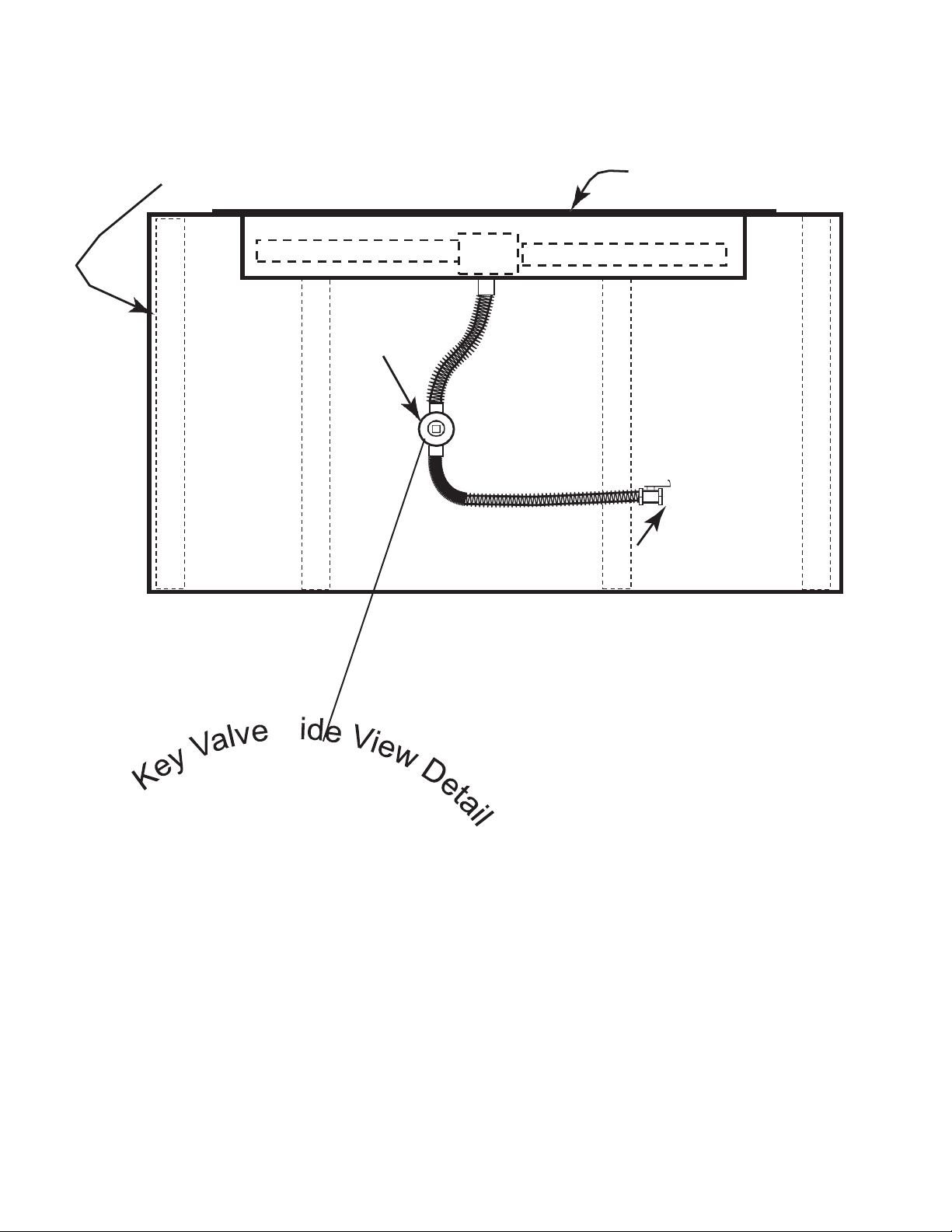
The pressure regulator and hose assembly (Fig. 7-1)
supplied with this outdoor-cooking gas appliance must
be used. Original and replacement pressure regulator
manufacturer for connection with a cylinder connecting
ed as Type.
f.
The propane-gas cylinder valve must be equipped with a
cylinder connection coupling device, described as Type
e. above. This
device is commonly described as an Acme thread quick
coupler.
g.
If thepropane-gas cylinder comes with a dust plug,place
The use of pliers or a wrench should not be necessary. Only
cylinders marked “propane” may be used.
To disconnect: Turn the hand nut counterclockwise until
detached (Fig. 7-1).
Important: Before using the unit, and after each time the
cylinder is removed and reattached, check
the hose for wear (see a.) and check all
connections for leaks.Turnoff the unit valves
andopen the main cylinder valve, thencheck
connections with soapy water. Repair any
leaks before lighting the unit.
CAUTION: Always turn the propane cylinder main valve
off after eachuse,andbeforemovingtheunit
and cylinder or disconnecting the coupling.
This valve must remain closed and the
cylinder disconnected while the appliance
stoppedbyasafetyfeaturewhen thecoupler
is disconnected.
Carefully inspect the hose assembly each time before the
gas is turned on. A cracked or frayed hose should be replaced
immediately.
If the appliance is stored indoors, the cylinder must be
disconnected and removed. Disconnected cylinders must be
stored outdoors, out of the reach of children, with threaded
valve plugs tightly installed, and must not be stored in a
building, garage, or any other enclosed area.
FOR YOUR SAFETY
a.
DO NOT store a spare propane-gas cylinder under or
near this appliance.
b.
ll the cylinder beyond 80-percent full.
c.
IFTHEINFORMATIONINa. ANDb. ISNOTFOLLOWED
EXACTLY, A FIRE CAUSING DEATH OR SERIOUS
INJURY MAY OCCUR.
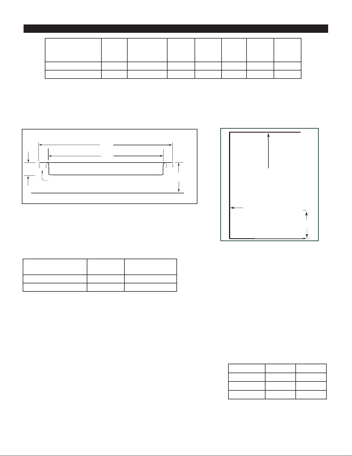
Fig. 7-1 Type I Acme thread quick coupler
the dust cap on the cylinder valve outlet whenever the
cylinder is not in use.
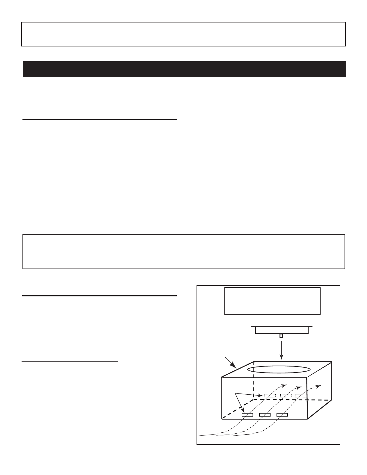
QUICK COUPLER OPERATION
QCC
Type 1
valve
Pressure
Hand wheel
U
Brass Acme
tting
Regulator
To connect the regulator/hose assembly to the propane-
tting:Pressthehandnutontheregulator
ttingonthecylindervalve.Turnthehand
nut clockwise to engage the threads and tighten until snug.
LEAK TEST
relief
valve
L
Liquid level
indicator
(optional)
Hand nut with Acme
thread
Vent
Hose
Turn on the gas supply, ignite the burner, and test at all
connectionsforleaksusing a soapywatersolution.If bubbles
appear, a leak is present. Turn off the gas and tighten at all
connections. Repeat until no leaks are present. If a leak
persists, turn off the gas supply and contact the local gas
companyordealer.NEVER USE AFLAME TO CHECK FOR
LEAKS.
Use LP propane gas tanks only with
these required measurements:
12 in. (diameter) x 18 in. (tall) with 20 lb.
capacity maximum.
IMPORTANT FOR YOUR SAFETY
READ AND FOLLOW ALL WARNINGS PROVIDED WITH THE PROPANE-GAS CYLINDER.
When operating this appliance with a propane-gas cylinder, these instructions and warnings MUST be observed.
FAILURE TO DO SO MAY RESULT IN A SERIOUS FIRE OR EXPLOSION.

CONVERTING TO A DIFFERENT GAS TYPE (MATCH LIT)
To convert MATCH LIT MANUAL UNITS (only) from propane to natural gas or from natural to propane gas,
carefully follow the steps below:
1.
SHUT OFF THE GAS SUPPLY TO THE UNIT AND ANY NEARBY ELECTRICAL SOURCES OR
APPLIANCES.
2.
If present, remove all decorative media from the unit.
3.
Remove the screws attaching the burner pan to your enclosure.
4.
Carefully detach the ex connector attached to the ori ce holder (see Fig. 3 ) and unscrew the ori ce
holder from the burner pipe (see Fig. 4 ).
5.
Remove the ori ce from the holder (see Fig. 4 ) and replace with the proper-sized one for your gas
requirement. Propane gas requires a 2.30mm(drill size) orifice.Natural gas require a 3.78mm orifice.
Note: If you are converting to and using natural gas you MUST install the air shutter over burner pipe to
cover theair holes (see Fig.4 ).For propane (L.P.)gas, remove theair shutter.
Replace the ori ce holder and reattach the connector from the valve (see Fig. 3).
The regulator must now be converted to the new gas type.
6.
To convert the regulator from propane gas to natural gas.
The appliance must be isolated from the gas supply piping system by closing , It's individual manual
shout off valva suring any pressure testing of the gas supply piping system. At test pressure equal to
or less than 1/2 psi (3.5 Kpa).
7.
Move the propane pipe from regulator (see Fig. 5) and replace with 3/8" natural gas pipe
(natural gas pipe package not included).
8.
Restore your gas supply and check for leaks per the INSTALLATION section. When no leaks are
detected, fasten the burner pan back into place on the enclosure and replace the decorative media.
Note: You should paste sticker lab on fire pit after changing NG system !
!
Fig. 4
Burner
pipe
ORIFICE
(Remove to change to a
different
gas type)
2.30mm-propane gas
3.78mm-natural gas
Air shutter (Used only with
natural gas. Removed for
propane gas.)
Connector from valve attached to
orifice holder on burner pipe
Fig. 1
Detach conn
ector from orifice holder when
changing orifice to a different gas type.
Fig. 3
Install gas pipe.
Fig. 2
Remove propane pipe.
NG Orifice & Air Shutter
NO. OA01
NG orifice size:3.78mm

A. Carefully inspect the carton for shipping damage. If any parts are missing or damaged, call yourdealer.
Do not attempt to install the appliance unless all parts are in good condition.
B. Correct installation is crucial to safe performance of your Outdoor FirePit.
C. Due to high temperatures, the Fire Pit must be located out of traffic areas and away from combustibles.
GLASS CRYSTAL INSTALLATION GUIDELINES
Rectangle brazier with a glass stone: 22LBS (size:9-12mm)
Round brazier with a glass stone: 20LBS (siz
e:9-12mm)
Square brazier with a glass stone: 19LBS (size:9-12mm)
#1
PARTS LIST
Replacement parts available from your local retailer
Figure 2
Figure 1
CAUTION –
Cuts may occur from the sharp edges on glass. Use safety gloves during the
placement of glass.
Pour the bag of lava granules or glass crystals into the Outdoor Fire Pit so that the burner is completely covered.
(See figures #1 and #2). These instructions apply to both round and rectangular burners.
Top View
GLASS CRYSTAL PLACEMENT
CAUTION: BURN HAZARD. GLASS CRYSTALS
WILL REMAIN HOT FOR SOME TIME AFTER USE.
YOU MUST MAINTAIN THE LAYOUT AS SHOWN TO ENSURE PROPER OPERATION OF YOUR FIRE
PIT. IF YOU NEED TO REPOSITION ANY MATERIAL TO MAINTAIN THE PROPER LAYOUT, USE HEAT
RESISTANT GLOVES OR ALLOW MATERIAL ADEQUATE TIME TO COOL BEFORE HANDLING.

OPERATING THE UNIT - LIGHTING AND EXTINGUISHING
FOR YOUR SAFETY, READ BEFORE LIGHTING
WARNING: IFYOUDONOTFOLLOWTHESEINSTRUCTIONSEXACTLY,AFIRE OREXPLOSIONMAY
RESULT, CAUSING PROPERTY DAMAGE, PERSONAL INJURY, OR LOSS OFLIFE.
A.
BEFORE LIGHTING, smell all around the unit C. Use only your hand to push in or turn the gas
control knob.Never use tools.If the knob will not
because some gas is heavier than air and will push in or turn by hand, DO NOT try to repair it.
B.
WHAT TO DO IF YOUSMELL GAS explosion.
1. Shut off the gas to the appliance.
ame.
3. If odor continues, immediately call your gas
MANUAL (MATCH) LIGHTING INSTRUCTIONS
1.
STOP! Read the safety information above. Fig. 15-1
2.
Lay a lighted long-stem match on the surface of the
decorative media near the burner ring (do not hold the
match in your hand) (Fig. 15-1) or use a lighted long-
necked butane lighter (Fig. 15-2)
3.
Push and slowly turn the control knob to the ON
position (see Fig. 15-3). Your burner should light.
4.
Observe the flame height when lit. Flame should be
3 to 13 inches high (see Fig 15-4). Apply match, then turn on gas
5.
If the burner does not light before the match goes out,
immediately turn the control knob to the OFF position. Fig. 15-3
6.
gas, and repeat steps 1-4 above.
7.
If your burner fails to light again, turn the controlknob
to the OFF position and contact your dealer or gas
supplier.
8.
To extinguish your gas burner, turnthe control knob ON OFF
to the OFF position. Be sure the control knob is turned
fully off to avoid any gas leakage.
Fig. 15-2 Fig. 15-4
long-necked butane lighter

REQUIREMENTS
1. Only non-combustible materials should come in direct contact with any part of the Fire Pit. Underneath area should
be non-combustible as well.
2. Only use ¾” gas supply line to the Fire Pit. Based on the selection of the fire pit size, the proper brass fittings should
be used to ensure a proper installation.
3. Determine the size of the round or square Fire Pit you are preparing to install (Refer to page 3).
4. You must provide a round or square cut out to place the fire pit into the non-combustible enclosure surround. Use
the pattern from the shipping carton for sizing.
5. Follow the local code requirements for the gas type being used. This Fire Pit should be installed in accordance with
local codes and ordinances or in the absence of local codes, with the latest National Fuel Gas Code, ANSI Z223.1
NFPA54 or CSA B149.1, Natural and Propane Installation Code inCanada.
6. Fire Pits create high temperatures, it is very important to have any combustibles at a safedistance.
7. Normal operation of the Fire Pit is with a battery box that is supplied with your system (Fig 4). The battery box has
12-feet of black sleeved wire that is to be passed through the junction box provided. This wire should not be cut or
spliced and the junction box can be placed in the facing of the vertical finish of the fire pit, if you place the wire under
ground you should install those wires into an approved protective conduit/sleeve material.
8. If (optional) 120VAC adapter (Pg.13) is going to be used to power this system it is required to follow all local codes
or National Electrical Code ANSI/NFPA 70 for installation of this electrical outlet. A breaker on wall switch with
approved outdoor outlet must be used to insure safety to this Fire Pit. When not in use the breaker should be in the
OFF position.
9. Fire pit should never be left unattended while in operation. It should always be a safe distance from all trees and
combustible landscape materials.
10. Construction of the finished fire pit should be stable and solid. From the bottom of the control box that houses the
gas valve and module, it should be a minimum if of 4-inches to the ground level. See figure #1. Drainage is critical to
ensure that water does not damage and valve components. Never install the fire ring system belowgrade.
11. CAUTION: A minimum of 18 square inches of cross ventilation (2 sides) is required to keep the components
in good working order.
12. The insulation square pad provided with the Fire Pit is to be placed foil up toward the bottom of pan on top of the
valve box.
13. Never fill the cavity under and around the valve box with any material, this is a provided air space necessary for
ventilation.
14. These products are designed for outdoor use only. Not approved for any indoor use.
15. This Fire Pit is designed to have decorative rock, Lava rock/Media covering the spoke burner. Optional concrete
logs can be added to consumers taste. Decorative Rock is not provided. When purchasing decorative rock it is
recommended to use minimum of 1-inch diameter rock as a base to fill the burner pan. Decorative glass cover
ing may be loosely scattered on top of rock if desired or non-combustible logs may be added for a campfire look.
NOTE: If using all glass media, glass must be a minimum of 1/4-inch diameter or larger.
16. Gas lines and fittings must be installed in to the non-combustible structure. All gas connections must be leak tested
before installation of the fire pit. Soapy water leak detection is required before regular use of the firepit.
17. Do not use material that will absorb moisture over time and will not release this moisture quickly. Moisture can boil
in this material and can rapidly break apart and cause damage or personal injury.
18. Never leave any other combustible material on top of the fire pit. This could cause unsafe operation of this system
and damage to the component that will not be covered under our warranty.
19. Cover the complete burner with lava or decorative Rock material (min. 1-inch diameter). Completely cover the
spoke burner, no more than 1 inch above the burner.
INSTALLATION OF FIRE PIT INTO AN APPROVED ENCLOSURE

*Do not use this fire pit for cooking.
*
Do not burn any other materials than are supplied with and intended for use in this fire pit.
*Do not pour water into fire pit.
*The installation of this product must conform with local codes.
*Do not use this fire pit if any part has been under water.
*Do not store a spare or disconnected liquid propane cylinder under or near this fire pit.
*After a period of storage, and/or non use, the propane fire pit should be checked for gas leaks and burner obstructions before use.
*Do not operate the propane fire pit if there is a gas leak present.
*Never use a flame to check for gas leaks.
*Combustible materials should never be within 10 feet of the top, back or sides of your propane fire pit.
*Do not put any other fire pit cover or anything flammable on, or beneath the fire pit.
*The propane fire pit should never be used by children. Children must be supervised when they are anywhere near the appliance.
*Users should be alerted to the hazards of high surface temperatures and keep a safe distance to avoid burning or clothing ignition.
*Pay attention when operating the fire pit. It is hot in use and should never be left unattended. Do not transit it while in operation.
*Should fire go out while burning, turn the gas valve off. Follow the instruction and wait five minutes before attempting to relight.
*Never use charcoal or any other solid fuel in the fire pit. Never parch clothing or other flammable materials on or near the fire pit.
*Never lean over the open fire pit or place hands or fingers on the upper portion of an operational unit.
*Keep ventilation openings in cylinder enclosure(FIRE PIT BODY) free and clear of debris.
*Do not rest feet on the fire pit.
*Please take out the battery when not using the fire pit for an extended length of time.
*Do not enlarge valve orifices or burner ports when cleaning the valve or burner.
*Cylinder supply system must be arranged for vapor withdrawal
*LP Tank used must include a collar to protect the cylinder valve
*Never fill the cylinder beyond 80% full
*Liquid propane gas is not natural gas. Only use propane for this fire pit.
*The conversion or attempted use of natural gas in a liquid propane unit or liquid propane gas in a natural gas unit is dangerous.
*Do not use this fire pit on vehicles or boats. Always operate the appliance on flat ground outdoors.
*Keep any electrical supply cord and the fuel supply hose away from any heated surfaces.
*Do not use this fire pit unless all parts are in place.
*Keep the appliance area clear and free from combustible materials, gasoline, and other flammable vapors and liquids.
*Inspect the hose before each use of the appliance
*The hose assembly must be replaced prior to the appliance being put into operation
if there is evidence of excessive abrasion or wear or if the hose is damaged.
* If the pvc component be damaged ,please send email to supplier : info@wonderfires.com
* Locating the hose out of pathways where people may trip over it or in areas where the hose may be subject to accidental damage.
* the burner must be replaced prior to the appliance being put into operation if it is evident that the burner is damaged.
*If the burner component be damaged,please send email to supplier : info@wonderfires.com
The LP-gas supply cylinder to be used must be:
1) constructed and marked in accordance with the U.S. Department of Transportation(D.O.T.)
Specificat ions for LP-Gas Cylinders, or the Standard for Cylinders, Spheres and Tubes for
Transportation of Dangerous Goods and Commission, CAN/CSA-B339, as applicable;
2) provided with a listed overfilling prevention device; and
3) provided with a cylinder connection device compatible with the connection for the appliance.
WARNING

INITIAL START UP
1. Turn gas ON. Ensure you have leak tested the fire pit before operating.
2. Press the ON button on the handheld transmitter. You will hear the ignitor probe sparking, light the gas and fre
pit will come on. WARNING: Do not stand over Fire Pit during ignition or operation due to high surface tempera
tures.
The distance between fireplace built-in stage and LP cylinder must be over 60 inches.(as the picture shows)
Put the gas tank in the metal stand. Make sure the gas tank sits on the metal stand completely.
Turn the wing screw on the outer part of the metal stand clockwise to ensure the gas tank tightly.
OPERATION
CAUTION: Children and adults should be alerted to the hazards on high surface temperatures and should stay away to
avoid burns or clothing ignition. Young children should be carefully supervised when they are in the area of the appliance.
WARNING: Do not use this appliance if any part has been under water. Immediately call a qualified service technician
to inspect the appliance and to replace any part of control system and any gas control, which has been under water.
SAFETY WARNINGS
1. Never leave the Fire Pit unattended during operation.
2. Clothing or other flammable materials should not be placed on or near the appliance.
3. Any guard or other protective device removed for servicing the appliance must be replaced prior to operating the
appliance.
4. Installation and repair should be done by a qualified service person. The appliance should be inspected before
use and at least annually by a qualified service person. More frequent cleaning may be required as necessary. It
is imperative the control compartment, burners and circulating air passageways of the appliance be kept clean.
5. Inspect the fuel supply connection before each use of the appliance.
6. Temporary storage of this appliance indoors is permissible only if it has been disconnected from its fuel supply
(Natural or L.P. gas line).
WARNING
1. This appliance is hot when operated and can cause sever burns if contacted.
2. Do not burn any solid fuels in this appliance.

Maintenance
WARNING: Any guard or protective device removed for servicing must be replaced prior to
operating the fire pit.
WARNING: Installation and repair should be done by a qualified service person. Fire pits should
be inspected prior to use and at least annually by a qualified service person.
WARNING: Ensure gas and power (if applicable) are shut off and fire pit is cool before servicing.
•Keep fire pit covered at all times when not in use.
•Keep any debris out of fire pit- clean as needed.
•Ring Cleaning: (1 x YR) If flames exhibit any abnormal shapes or behavior, or if burner fails to ignite properly, then
the burner holes may require cleaning. The appliance can be cleaned by carefully removing the logs and media to allow
access to burner. Use a brush to carefully remove dust, spider webs, and loose particles from base, logs, and fire ring
itself. If evidence of damage, fire ring must be replaced with fire ring specified bymanufacturer.
•Ignition Battery: For changing, simply unscrew cap, replace battery, and tighten cap.
Troubleshooting
Below are some potential causes and countermeasures to the symptoms indicated in bold. Please contact your retailer or
certified technician for service & repair.
Below are some potential causes and countermeasures to the symptoms indicated in bold. If still unable to resolve issue, please
contact your retailer or certified technician.
Will Not Light
1. Air in gas line. If new install, may take several attempts to purge air
2. Debris in gas line. Confirm gas line is clear (insulation, dirt, plastic, excessive pipe sealer etc..)
3. Gas Pressure Improper Confirm proper gas pressure found (Section 1)
4. Spark Igniter needs adjusted Spark Igniter Must be correctly aligned with burner holes.
5. Weak Batteries Replace batteries.
6. Wire is shorted Re-route wire away from conductive materials.
Will Not Stay Lit
1. Gas Pressure Improper Confirm proper gas pressure found (Section 1)
2. Improperly applied media Review Media in (Section 5)
Noise
1. Whistling Sound Change Flex line routing.
This manual suits for next models
4
Table of contents
Other PATIO HQ Outdoor Fireplace manuals
Popular Outdoor Fireplace manuals by other brands

Regency
Regency Horizon HZO42-NG Owners & installation manual

Kingsman Fireplaces
Kingsman Fireplaces FP2085NT manual

Epic Fire Design
Epic Fire Design Vulcan Fire Module VFM owner's manual

PHI VILLA
PHI VILLA E02GS015 Use and care guide

Bond
Bond Cedar Ridge HYFP40205-132 owner's manual

Bond
Bond PGF6501-1 owner's manual

Upland
Upland UI-GFT-31269-BK Assembly instructions

Ashley
Ashley Signature P791 user guide

Style selections
Style selections SRGF11634-11 Assembly instructions

Endless Summer
Endless Summer WAD1412SP owner's manual

pleasant hearth
pleasant hearth LANGSTON OFW821RC manual

Outdoor Plus
Outdoor Plus MARTILLO manual