Patlite WDT-4LR-Z2 User manual

Wireless Data Acquisition System
TYPE:WDT-4LR-Z2
TYPE:WDT-5LR-Z2
TYPE:WDT-6LR-Z2
TYPE:WDR-LE-Z2
Instruction Manual
[Web version]
Notice to Customer
Thank for your purchasing our PATLITE products.
The WDT-4LR-Z2,WDT-5LR-Z2 and WDT-6LR-Z2 products are used exclusively with LR4/LR5/LR6 signal towers.
Request the installation and wiring be performed by a professional contractor if construction work is involved.
Prior to installation, read this manual thoroughly before using this product to ensure correct use.
Re-read this manual before conducting maintenance, inspections, repairs, and so on. If you have any questions about this
product, please contact your PATLITE sales representative listed on the back of this manual.
To the Contractor
Prior to installation, read this manual thoroughly to ensure it is installed correctly.
Return this manual to the customer.
B95100527_06

Wireless Data Acquisition System Instruction Manual
2
■Table of Contents
Notice to Customer ............................................................................................................................................................1
To the Contractor ...............................................................................................................................................................1
1. Before you begin................................................................................................................................................................4
1.1 About Safety Symbols ................................................................................................................................................. 4
1.2 Safety Precautions....................................................................................................................................................... 5
2. Contents.............................................................................................................................................................................8
2.1 About the Contents......................................................................................................................................................8
(1) WDT-4LR-Z2/WDT-5LR-Z2/WDT-6LR-Z2.................................................................................................................8
(2) WDR-LE-Z2...............................................................................................................................................................8
3. Models................................................................................................................................................................................9
3.1 About Models...............................................................................................................................................................9
(1) WDT (transmitter)......................................................................................................................................................9
(2) WDR (receiver)..........................................................................................................................................................9
4. Part Names and Dimensions...........................................................................................................................................10
4.1 About Part Names and Dimensions ..........................................................................................................................10
(1) WDT (transmitter)....................................................................................................................................................10
(2) WDR (receiver)........................................................................................................................................................ 11
5. Operation Overview .........................................................................................................................................................12
5.1 About the WD System ...............................................................................................................................................12
5.2 System Configuration ................................................................................................................................................12
(1) Glossary ..................................................................................................................................................................12
(2) System Configuration..............................................................................................................................................13
5.3 WD System Operation Overview...............................................................................................................................15
5.4 About Visualization Application Software...................................................................................................................15
5.5 Function Table............................................................................................................................................................16
(1) WDT ........................................................................................................................................................................16
(2) WDR........................................................................................................................................................................17
6. Installation........................................................................................................................................................................19
6.1 Before Installation......................................................................................................................................................19
(1) What is the WD Wireless Network? ........................................................................................................................19
(2) About Grouping and ExtendedPanID......................................................................................................................21
(3) About the MAC Address..........................................................................................................................................22
(4) How many WDT you can connect to WDR .............................................................................................................22
6.2 About the Installation Environment............................................................................................................................23
(1) Installation Environment Main Points ......................................................................................................................23
(2) About the Signal Tower Power Supply status .........................................................................................................26
6.3 Equipment Settings....................................................................................................................................................26
(1) Setup Information....................................................................................................................................................26
(2) Equipment Settings .................................................................................................................................................27
6.4 Equipment Installation ...............................................................................................................................................27
(1) WDT Installation ......................................................................................................................................................27
(2) WDR Installation......................................................................................................................................................28
(3) Check the Connection Between WDT and WDR....................................................................................................28
7. Operation .........................................................................................................................................................................29
7.1 How to Use the WDT.................................................................................................................................................29
(1) WDT Wiring.............................................................................................................................................................29
(2) Attaching and Detaching the WDT..........................................................................................................................30
(3) Setting up the WDT Main Unit.................................................................................................................................36
(4) WDT DIP Switch Operations...................................................................................................................................37
(5) Checking WDT Indicator Operation.........................................................................................................................38
(6) Initializing the WDT .................................................................................................................................................38
7.2 How to Use the WDR.................................................................................................................................................39
(1) Mounting the WDR..................................................................................................................................................39
(2) WDR Wiring.............................................................................................................................................................41
(3) Setting up the WDR Main Unit ................................................................................................................................45
(4) WDR DIP Switch Operations...................................................................................................................................46

Wireless Data Acquisition System Instruction Manual
3
(5) Initializing WDR LAN communication settings ........................................................................................................47
8. Function Details ...............................................................................................................................................................48
8.1 WDT Function............................................................................................................................................................48
(1) Functions Related to Wireless Data Transmission..................................................................................................48
(2) Functions Related to Signal Tower Input.................................................................................................................51
(3) Install, Initialize, and Change Settings Functions....................................................................................................54
9. Replacement and Optional Parts.....................................................................................................................................56
9.1 Replacement Parts ....................................................................................................................................................56
(1) WDT ........................................................................................................................................................................56
9.2 Optional Parts............................................................................................................................................................56
10.Troubleshooting ...............................................................................................................................................................57
10.1 Troubleshooting.........................................................................................................................................................57
(1) WDT ........................................................................................................................................................................57
(2) WDR........................................................................................................................................................................58
11.Specifications...................................................................................................................................................................59
11.1 Specifications.............................................................................................................................................................59
(1) WDT ........................................................................................................................................................................59
(2) WDR........................................................................................................................................................................60

Wireless Data Acquisition System Instruction Manual
4
1. Before you begin
1.1About Safety Symbols
To prevent injuries to the user and other personnel, as well as to prevent damage to assets, note the following:
◆The following symbols classify warnings and cautions, and describe the level of harm and damage that will occur when the
corresponding instructions are ignored.
WARNING
This symbol indicates, "Failure to follow the instructions may lead to death or serious injury."
CAUTION
This symbol indicates, "Failure to follow the instructions may lead to injury or property
damage."
◆The following symbols classify and describe the content of associated messages.
Prohibited
This symbol identifies "Prohibited" operations that should never be carried out.
Mandatory
This symbol identifies "Mandatory" instructions that should always be carried out.
This symbol identifies general "Caution" related information.

Wireless Data Acquisition System Instruction Manual
5
1.2Safety Precautions
WARNING
Prohibited
◆This Wireless DataAcquisition System (hereafter referred to as "this product") is an attachment for
existing machinery and equipment that work with LR series signal towers (LR4,LR5 and LR6). This
product sends changes in the operation status of signal towers via a wireless transmitter to a
receiver that collects the data. Do not use this product for any other purpose.
◆Do not use this product in the vicinity of implanted cardiac pacemakers and other medical
equipment, as this product's radio waves may affect the performance of these devices.
◆Do not use or install the receiver (WDR-LE-Z2) in locations where liquids such as water is present,
oil will splatter, or locations that are humid or dusty. Failure to follow these instructions could result
in fire, electric shock or product failure.
◆To prevent accidents, do not use this product other than for its intended purpose and do not run
operations or maintenance other than those described in this manual.
◆This product is not intended for use where high reliability is required and where human life is
involved, such as medical equipment, atomic energy equipment and machinery, aviation and
aerospace, transportation, and control of other equipment. If this product is used for these
applications, we cannot be held responsible in the event of injury or property damage.
◆Do not modify or disassemble this product. Failure to follow these instructions could result in fire or
electric shock.
◆Do not use this product when there is condensation. Failure to follow these instructions could result
in fire or electric shock.
◆Do not allow liquids to enter the receiver (WDR-LE-Z2), and do not allow it to have contact with
metallic objects. Failure to follow these instructions could result in fire or electric shock.
Mandatory
◆Request the installation and wiring be performed by a professional contractor if construction work is
involved. Failure to follow this instruction could result in fire, electric shock or falls.
◆Turn off the power before performing any electric wiring or product installation. Failure to follow this
instruction could result in electric shock.
◆Always use a power supply within the operating voltage range. Failure to follow this instruction
could result in fire or product failure.
◆In places such as aircraft and hospitals, turn off this product where usage of wireless devices is
prohibited and where its radio waves affect surrounding equipment.
◆We cannot foresee all circumstances concerning the handling and dangers associated with this
product. Therefore, not every possible danger is indicated in this instruction manual. To prevent
accidents when operating or maintaining this product, in addition to the safety guidelines identified
in the instructions of this manual, follow all general safety guidelines.
◆In the unlikely event that there is an abnormal situation such as smoke or odors emitting from the
product, immediately cut the power supplied to the product. Continued use of the product in this
condition could result in fire or electric shock.

Wireless Data Acquisition System Instruction Manual
6
CAUTION
Prohibited
◆Do not install this product near other electrical appliances. If you install this product near a
facsimile, personal computer, television, microwave oven, or equipment using a motor, this product
may not operate properly.
◆Do not use this product with the O-ring removed. Waterproofing will be affected, and potentially
cause equipment failure.
◆Do not use this product in applications that require a high-degree of reliability or real-time
performance. If there are communication problems, this product cannot retrieve accurate data.
◆Do not use this product near fire, in hot or humid environments, or where corrosive or flammable
gas is present. Failure to follow this instruction could cause a malfunction and the product may not
operate properly.
◆Do not use or store this product in the following locations. Failure to follow this instruction could
result in a malfunction or product failure.
Environments with poor breathability and ventilation
Near equipment that generate strong electrical or strong magnetic fields
Places exposed to direct sunlight
Locations subject to shock and vibration
Near heating appliances
Environments where there is dust, iron powder, and so on
Places near fire or environments with high temperatures and humidity
Locations where the product may experience a drop
Locations exposed to salty sea air
Mandatory
◆Operate this product only after thorough testing in the customer environment.
◆Pay close attention to the polarity of the power supply before connection. Connecting the power
supply incorrectly may cause equipment failure.
◆To clean this product, wipe with a soft cloth dampened with water. Do not wipe with cleaners
containing thinners, benzene, gasoline, or oil.
◆Although this product has a high level of security, there is the potential for third-parties to intercept
communications as this product uses radio waves.
◆When using this product, pay close attention to the following:
Due to the nature of radio waves, communication can be disabled even over insignificant
distances as a result of noise or other environmental factors.
Do not use this product near chemicals. This product could melt or become deformed if any
chemicals adhere to it.
To prevent static electricity, discharge the static electrical charge in your body before starting
work. (You can discharge static electricity by touching your hand on grounded metal objects.)

Wireless Data Acquisition System Instruction Manual
7
CAUTION
◆Operation under the following conditions could cause the wireless communication distance to
become shorter than specified, and increase reaction times:
Metal obstructions, such as steel doors or reinforced concrete, are between the transmitter and
receiver.
Transmitter or receiver is mounted on a metal surface.
When used near powerful radio waves, such as those emitted by broadcasting stations.
When used near power lines or other high-voltage lines.
◆About the Operating Environment
We have tested the product with out of the box computers in a normal operating environment.
However, depending on your operating environment, which includes the computer main unit,
peripheral devices and applications in use, there may be cases where this product will not run
properly.
◆The software copyrights are held by our company.
Do not use this software in other products, or duplicate or modify a portion or all the software
without prior written permission.
◆Disposing this product
When disposing of this product, follow the rules and regulations on how to handle recyclable
materials as outlined in your community.
◆About this manual
The contents of this manual are subject to change without notice.
Images in this manual are for illustration purposes only, and may differ from the actual product.
Additionally, the illustration may hide parts of the product for ease of explanation.
This manual is copyrighted. No part of the manual, including drawings or technical information,
can be copied or duplicated in any manner, without prior consent.
When transferring ownership of this product, include the instruction manual (digest version).
If you have any questions or need further information, contact your nearest PATLITE sales
representative.
We cannot warrant against breakdowns caused by disassembling this product, natural disasters, or handling of
this product that is contrary to any warnings or precautions.
Avoid using this product in ways other than those described in this manual.
We cannot be held responsible for damages and injuries caused by failing to pay attention, or failing to follow
precautions, when operating or running maintenance on this product.

Wireless Data Acquisition System Instruction Manual
8
2. Contents
2.1About the Contents
(1) WDT-4LR-Z2/WDT-5LR-Z2/WDT-6LR-Z2
Product: 1 unit
Instruction Manual (digest version): 1 copy
(2) WDR-LE-Z2
Product: 1 unit
Ferrite core: 1
Instruction Manual (digest version): 1 copy

Wireless Data Acquisition System Instruction Manual
9
3. Models
3.1About Models
(1) WDT (transmitter)
Model
WDT-4LR-Z2(Compatible LR Series Signal Tower: LR4)
WDT-5LR-Z2(Compatible LR Series Signal Tower: LR5)
WDT-6LR-Z2(Compatible LR Series Signal Tower: LR6)
①LR Signal Tower Models
This product
Compatible LR Series Signal Tower
Model
Model
Size
Rated Voltage
WDT-4LR-Z2
LR4-□-02
Ф40
24 VDC
LR4-□-M2
100 to 240 VAC
WDT-5LR-Z2
LR5-□-01
Ф 50
12 VDC
LR5-□-02
24 VDC
WDT-6LR-Z2
LR6-□-02
Ф 60
24 VDC
LR6-□-M2
100 to 240 VAC
(2) WDR (receiver)
Model
WDR-LE-Z2 (LE: LAN/USB connector model for overseas only)

Wireless Data Acquisition System Instruction Manual
10
4. Part Names and Dimensions
4.1About Part Names and Dimensions
(1) WDT (transmitter)
①Part Names
②Part Dimensions
Front View (units: mm) Front View (units: mm)

Wireless Data Acquisition System Instruction Manual
11
(2) WDR (receiver)
①Part Names (main unit)
Front View Bottom View
②Part Names (inside the main unit)
Front View (inside the main unit)
③Part Dimensions
Front View Front View (inside the main unit) Bottom View

Wireless Data Acquisition System Instruction Manual
12
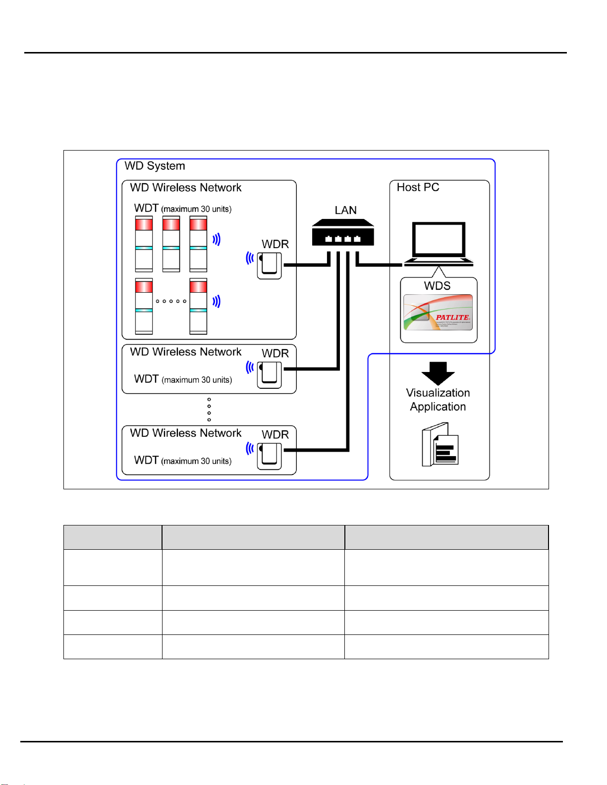
5. Operation Overview
5.1About the WD System
To collect data available on equipment in your facility, the WD system transmits associated information (such as equipment
operation data) to a host computer over the WD wireless network. By using visualization application software, you can use
collected information to: a) accurately view utilization of capacity b) trigger improvement activities, and c) optimize
operations. This application is not limited to production facilities and can be applied to other areas.
5.2System Configuration
(1) Glossary
Term
Description
WD system
Generic name to identify the whole system. Includes multiple WD wireless
networks and the host PC.
WD wireless network
The part of the wireless network that consists of one WDR and multiple WDT
(up to 30 units).
Signal Tower information
Status of the signal tower from which the WD system collects data.
WDT
Transmitter on a WD wireless network. The WDT collects signal tower
information from a signal tower and transmits the information wirelessly to a
WDR.
WDR
Receiver on a WD wireless network. The WDR receives signal tower
information from multiple WDT and transmits the information to the host PC.
Host PC
Personal computer for operation of the WD system.
WDS
Application software for WDT and WDR settings, and for collecting signal
tower information in the WD system as CSV log data.
Visualization application
software
Application software installed on the host PC. Use this application to display
information collected by the WD system in a Gantt chart or graph. Must be
provided by the customer.*
Maintenance PC
At maintenance, personal computer for setting up the WDT and WDR.
* For information on visualization application software, refer to ☞"5.4 About Visualization Application Software".
Wireless Data Acquisition System Instruction Manual
13
(2) System Configuration
①Run Time System Configuration
Diagram
Configuration
Item
Number of configuration items
Models
WDT
1 to 30 units*1 per receiver
WDT-4LR-Z2 or WDT-5LR-Z2 or
WDT-6LR-Z2
WDR
1 to 20 units*2
WDR-LE-Z2
WDS
1
WDS-WIN01
Host PC*3
1
–
* 1 For more information, refer to ☞"6.1(4) How many WDT you can connect to WDR".
* 2 When collecting CSV log data with WDS-WIN01.
* 3 When connecting the WDR directly to the host PC with a LAN cable, use a cross cable.

Wireless Data Acquisition System Instruction Manual
14
②Maintenance System Configuration (using the power supply input kit)
Diagram
Configuration
Item
Number of configuration items
Models
WDT
Number as required
WDT-4LR-Z2 (This Product)
WDT-5LR-Z2 (This Product)
WDT-6LR-Z2 (This Product)
Power supply input kit (option)
1
WDX-4LRB
WDX-5LRB
WDX-6LRB
AC Adaptor (option)
1
ADP-001
WDR
1
WDR-LE-Z2
WDS
1
WDS-WIN01
Maintenance PC
1
–
LAN Cable*2 *3
1
–
USB Cable*4 *5
1
–
* 2 When configuring the WDR LAN settings, connect with a LAN cable.
* 3 When connecting the WDR directly to the host PC with a LAN cable, use a cross cable.
* 4 Use a USB cable 3 m or shorter.
* 5 Do not connect the LAN and USB cables at the same time.

Wireless Data Acquisition System Instruction Manual
15
5.3WD System Operation Overview
WDT transmits signal tower information via the WDR to the WDS on the host PC.
WDS collects the information and stores it as CSV log data. Load the data into visualization application software.
You can also load WDR signal tower information directly into the visualization application software.
5.4About Visualization Application Software
CAUTION
◆The customer needs to provide the visualization application software.
◆Select a visualization application software suitable for customer visualization requirements.
There are two ways the WD system passes collected information to the visualization application software: 1) CSV Assisted
2) Socket Communication.
◆Pattern 1: CSV Assisted
WD System
Transmit Signal Tower
information
⇒
WDS
Save loaded signal tower
information as CSV data
⇒
Visualization Application Software
Visualization of loaded CSV data
Visualization Application Software Preparation
References
1
When using software packages from PATLITE
partners that support the WD system
☞Please contact our sales office. *
2
When customer develops their own solution
Refer to ☞this manual.
Refer to ☞"WDS-WIN01 Instruction Manual".
◆Pattern 2: Socket Communication
WD System
Transmit Signal Tower information
⇒
Visualization Application Software
Read signal tower information
Visualize data
Visualization Application Software Preparation
References
1
When using software packages from PATLITE
partners that support the WD system
☞Please contact our sales office.*
2
When customer develops their own solution
Refer to ☞this manual.
Refer to ☞"Application Notes".

Wireless Data Acquisition System Instruction Manual
16
5.5Function Table
(1) WDT
①Wireless Data Transmission Function
Function
Description
References
Signal Tower
Transmission
Information
Function whereby the WDT transmits the status of the
signal tower wirelessly to the WDR. There are two
transmission modes for the transmission:
• Immediate transmission mode
Send immediately after the status of the signal tower
changes.
• Request transmission mode
Send only after receiving a signal tower status
request from the host PC.
Refer to ☞"8.1(1)①
Signal Tower
Transmission
Information"
Select Signal Tower
Information Format
This function is for selecting one of two types of signal
tower information, Extended Format or Standard Format.
Select using a DIP switch.
• Extended Format
Sets up six types of signal tower information.
• Standard Format
Format compatible with WDT-5E-Z2 and
WDT-6M-Z2.
Sets up five types of signal tower information.
Refer to ☞"8.1(1)②
Select Format of Signal
Tower Information"
Maintain Signal Tower
Status
When a transmission failure occurs between the signal
tower signal input and the actual transmission, this
function temporarily retains the transmission information in
the WDT.
Refer to ☞"8.1(1)③
Maintain Signal Tower
Status"
Mesh Network
Transmission
Function that automatically connects the WDT over the
optimum communication route to the WDR for transmitting
the information.
Refer to ☞"8.1(1)④
Mesh Network
Transmission"
Simple Counter
Function
By using a pulse input on a single signal wire, count up the
number of pulse inputs (increment 1 at a time) and store
the accumulated value (count) on the WDT.
The count is sent only when a request is received
from the host PC.
You can use WDS-WIN01 (1.02 or later) to clear the
count to zero.
Refer to ☞"8.1(1)⑤
Simple Counter
Function"
There are two ways to select the counter signal wire:
"Using a DIP switch on the unit" (selection fixed as blue)
and "Using WDS-WIN01" (any selection).
Refer to ☞"8.1(1)⑥
Selecting the signal wire
for a simple counter"

Wireless Data Acquisition System Instruction Manual
17
②Signal Wire Input Functions
Function
Description
References
Determine Signal
Tower Input
Function for determining the input status from the signal
tower. There are two settings, Normal and Flashing. You can
set this up on the WDS-WIN01 software.
This function cannot determine the input status from inputs
in a simple counter function.
Refer to ☞"8.1(2)①
Determine Signal
Tower Input"
③Install, Initialize, and Change Settings Functions
Function
Description
References
Display
Communication
Quality
Displays the communication quality as one of three levels for
the wireless connection between the WDT and WDR.
Refer to ☞"8.1(3)①
Display
Communication
Quality"
Display WDT Call
When the device receives a specific command from the host
PC, the indicator flashes blue for approximately 10 seconds.
Refer to ☞"8.1(3)②
Display WDT Call"
Display WDT MAC
address
A label on the body of the WDT identifies its MAC address.
Refer to ☞"6.1(3)
About the MAC
Address"
Periodic
Transmission
Function for automatically transmitting from the WDT the
current signal tower status. Select by toggling a DIP switch
on the unit.
Refer to ☞"8.1(3)③
Periodic Transmission"
Initialization
Function for resetting the unit to its factory default settings.
Select by toggling a DIP switch on the unit.
Refer to ☞"8.1(3)④
Initialization"
(2) WDR
CAUTION
◆You cannot operate the Contact Switch Function from the WDS. You can create these with the
visualization application software provided by the customer.
①Communication Functions
Function
Description
WDT Wireless
Communication
Function
Function to communicate with multiple WDT wirelessly.
Using this function, you can communicate with up to 30 WDT units.

Wireless Data Acquisition System Instruction Manual
18
Host PC Communication
Function
Function to communicate with one host PC via LAN or USB.
You can connect one session at a time for a LAN connection.
②Install, Initialize, and Change Settings Functions
Function
Description
Display Power Supply
Status
Function for using an indicator (green LED) to display the WDR power supply
input status. Green light: Power ON, light off: Power OFF
Initialize Network
Settings
Function for resetting the LAN network settings to its factory default. Select by
toggling a DIP switch on the unit.
③Contact Terminal Block Control Function
Function
Description
Contact Switch Function
By receiving commands from the host PC, this function controls the ON/OFF
state of the contact terminal. This is a normally open contact.
Display Contact Status
This function displays the state of the contact with an LED indicator (red OUTPUT
LED). Red light: ON, light off: OFF

Wireless Data Acquisition System Instruction Manual
19
6. Installation
6.1Before Installation
(1) What is the WD Wireless Network?
①About the WD Wireless Network
The WD wireless network operates on the IEEE802.15.4 (ZigBee) compliant 2.4 GHz frequency.
Although it runs on the same 2.4 GHz frequency as a wireless LAN (Wi-Fi), because it conforms to IEEE802.15.4 the WD
wireless network can operate without connecting to a wireless LAN. However, if the frequencies used overlap, the WD
wireless network could experience transmission delays and other communication issues.
The wireless communication is encrypted. The encryption standard used is AES-CCM (Advanced Encryption
Standard-Counter with CBC-MAC), with an encryption key of 128 bits.
②About Selecting a Wireless Channel
The WD wireless network uses 16 wireless channels (CH11 to CH26).
Select a wireless channel to avoid conflict with the frequency band of the LAN's wireless channel in your installation
environment.
The relationship between frequency bands of channels on the WD wireless network and on the wireless LAN is as follows.

Wireless Data Acquisition System Instruction Manual
20
The frequency of channels on the WD wireless network is as follows.
Channel
Mid-range frequency
(MHz)
Bandwidth (MHz)
CH11
2,405
2
CH12
2,410
2
CH13
2,415
2
CH14
2,420
2
CH15
2,425
2
CH16
2,430
2
CH17
2,435
2
CH18
2,440
2
CH19
2,445
2
CH20
2,450
2
CH21
2,455
2
CH22
2,460
2
CH23
2,465
2
CH24
2,470
2
CH25
2,475
2
CH26
2,480
2
③Example Wireless Channel Selection
When the wireless LAN uses three channels (CH1, CH6, and CH11), select either CH15, CH20, CH25, or CH26.
In most cases selecting CH25 or CH26 will enable you to avoid the wireless LAN channels.
This manual suits for next models
3
Table of contents


