Paton PSI 270 PRO 400 V User manual
0 | Pag e PATON®PSI PRO 270 / 350 400 V DC MIG/MAG TIG/MMA

1 | Pag e PATON®PSI PRO 270 / 350 400 V DC MIG/MAG TIG/MMA
TABLE OF CONTENTS
1.
GENERAL INFORMATION ......................................................................................
4
1.1.
TECHNICAL CHARACTERISTICS ..........................................................................
6
1.2.
CONTROLS AND CONNECTORS ...........................................................................
7
2.
SETTING THE WELDING UNIT INTO OPERATION ............................................
9
2.1
PROPER USE ..............................................................................................................
9
2.2
REQUIREMENTS FOR INSTALLATION ................................................................
10
2.3.
CONNECTION TO A POWER SUPPLY SYSTEM ..................................................
10
2.4.
REQUIREMENTS FOR AN ELECTRICAL OUTLET .............................................
10
3.
MANUAL COVERED-ELECTRODE ARC WELDING PROCESS (MMA) ....
11
3.1
PREPARING THE WELDING UNIT FOR OPERATION ........................................
11
3.2
OPERATIONAL CYCLE OF THE MANUAL ARC WELDING PROCESS ...........
11
3.3.
INCREASED-CURRENT ARC STARTING .............................................................
12
3.4.
REDUCED-VOLTAGE WELDING MODE ..............................................................
12
3.5.
PROTECTION AGAINST ELECTRODE STICKING ..............................................
13
3.6.
SETTING THE SLOPE OF THE VOLT-AMPERE CHARACTERISTIC OF THE
WELDING UNIT ........................................................................................................
13
3.7.
SHORT ARC WELDING MODE ...............................................................................
14
3.8.
REDUCTION OF OPEN-CIRCUIT VOLTAGE ........................................................
14
3.9.
WELDING AT PULSE WELDING CURRENT ........................................................
14
4.
ARGON ARC WELDING PROCESS (TIG) ..........................................................
15
4.1.
PREPARING THE WELDING UNIT FOR OPERATION TIG –LIFT ....................
15
4.2
OPERATIONAL CYCLE OF THE WELDING PROCESS TIG –LIFT ...................
17
4.2.1
TIG-LIFT CONTACT ARC STARTING FUNCTION ..............................................
17
4.3
OPERATIONAL CYCLE OF THE WELDING PROCESS WITH TIG-2T ..............
18
4.3.1
OPERATIONAL CYCLE OF THE WELDING PROCESS WITH TIG-2T ..............
18
4.3.2
TIG-2T CONTACTLESS ARC STARTING FUNCTION .........................................
19
4.4.
PREPARING THE WELDING UNIT FOR OPERATION TIG –4T ........................
20
4.4.1
OPERATIONAL CYCLE OF THE WELDING PROCESS WITH TIG-4T ..............
20
4.4.2
TIG-4T CONTACTLESS ARC STARTING FUNCTION .........................................
21
4.5
INITIAL CURRENT (PILOT ARC CURRENT) SETTING ......................................
21
4.6
LINEAR INCREASE OF WELDING CURRENT .....................................................
21
4.7.
LINEAR DECREASE OF WELDING CURRENT ....................................................
22
4.8.
WELDING CRATER CURRENT ...............................................................................
22
4.9.
WELDING AT PULSE WELDING CURRENT ........................................................
22
5.
SEMIAUTOMATIC ARC WELDING PROCESS (MIG/MAG) .........................
23
5.1.
PREPARING THE WELDING UNIT FOR OPERATION ........................................
24

2 | Pag e PATON®PSI PRO 270 / 350 400 V DC MIG/MAG TIG/MMA
5.2.
OPERATIONAL CYCLE OF THE WELDING PROCESS - MIG/MAG .................
25
5.2.1
OPERATIONAL CYCLE OF THE WELDING PROCESS - MIG / MAG 2T ..........
26
5.2.2
CYCLE WELDING PROCESS - MIG / MAG FUNCTION 4T& 4T_ ......................
26
5.3
FUNCTION OF PRETREATMENT GAS CLEANING ............................................
27
5.4
FUNCTION OF INCREASES THE WIRE FEED SPEED ........................................
27
5.5
FUNCTION OF BURNING OUT AT THE END OF WELDING .............................
28
5.6
FUNCTION OF POSTWELD GAS CLEANING .......................................................
28
5.7
INDUCTANCE CONTROL FUNCTION ...................................................................
28
5.8.
WELDING AT PULSE WELDING VOLTAGE ........................................................
28
6.
SETTING THE WELDING UNIT ..............................................................................
29
6.1.
SWITCHING TO THE REQUIRED FUNCTION ......................................................
30
6.2
CHOOSING A LANGUAGE ON THE DEVICE .......................................................
30
6.3.
SWITCHING TO THE REQUIRED WELDING PROCESS .....................................
30
6.4.
RESETTING ALL FUNCTIONS CURRENT WELDING METHOD ......................
30
7.
GENERAL LIST OF FUNCTION SEQUENCES ..................................................
31
7.1
MANUAL ARC WELDING PROCESS (MMA) .......................................................
31
7.2
ARGON SHIELDED TUNGSTEN-ARC WELDING PROCESS (TIG) ...................
31
7.3.
SEMIAUTOMATIC ARC WELDING PROCESS (MIG/MAG) ...............................
32
7.3.1.
WIRE FEEDER FUNCTION WELDING PROCESS (MIG/MAG) ..........................
33
8.
MAINTENANCE ........................................................................................................
33
9.
OPERATION WITH AN ELECTRIC GENERATOR ...............................................
34
10.
STORAGE ...................................................................................................................
34
11.
TRANSPORTATION ..................................................................................................
34
12.
SPECIFICATION DATA ............................................................................................
34
13.
DELIVERY SET ..........................................................................................................
35
14.
WARRANTY ...............................................................................................................
35
15.
WASTE ELECTRICAL & ELECTRONIC EQUIPMENT .........................................
37
16.
SAFETY INSTRUCTIONS .........................................................................................
37
17.
ELECTRICAL SCHEMATIC DIAGRAM .................................................................
40
18.
ACCEPTANCE CERTIFICATE .................................................................................
41
19.
WARRANTY CARD ..................................................................................................
42

3 | Pag e PATON®PSI PRO 270 / 350 400 V DC MIG/MAG TIG/MMA
EC Declaration of Conformity
The following products have been tested by us with the listed standards
and found in compliance with the European Community Low Voltage
Directive 2014/35/EU and Electromagnetic Compatibility Directive
2014/30/EU.
AUTHORISED
REPRESENTATIVE:
MASTERWELD Sp. z o.o., Poland
Przemysłowa 14 st.,
PL35105 Rzeszów
Ust.ID. PL8133751525
MANUFACTURER
ADDRESS
Limited Liability Company “Pilot Plant of Welding
Equipment of Electric Welding Institute named after
E.O. Paton”
Ukraine, 03045, Kyiv, 66 Novopyrohivska St.
PRODUCT:
DIGITAL SEMIAUTOMATIC INVERTER
PATON PSI 270 PRO / 350 PRO 400V
DC MIG/MAG TIG/MMA
The statement is based on a single evaluation of one sample of above mentioned products. It
does not imply an assessment of the whole production. The manufacturer should ensure that all
product in series production are in conformity with the product
sample detailed in this report.
The applicant should hold the whole technical report at
disposal of the competent all the right.
Applied EC Directives:
2014/35/EU (Low Voltage)
2014/30/EU (Electromagnetic Compatibility)
Applied Standards:
EN 60204-1:2006. Safety of machinery - Electrical equipment of
machines –Part 1: General requirements; EN 60974-1:2012 Are
welding equipment –Part 1: Welding power sources; EN 60974-
10:2014 Are welding equipment –Part 10: Electromagnetic
compatibility (EMC) –requirements.
Issued Date: 12 September 2017
Expiry Date: 11 September 2022
General Manager
We, MASTERWELD Sp. z o. o., hereby declare that specified above conforms covering
European Parliament and Council Directives, 2014/35/EC Low Voltage Directive of 26
February 2014 and 2014/30/EU Electromagnetic Compatibility of 26 February 2014.
The CE mark above can be used under the responsibility of manufacturer. After completion of an EC
declaration of conformity and compliance with all relevant EU Directives.

4 | Pag e PATON®PSI PRO 270 / 350 400 V DC MIG/MAG TIG/MMA
ATTENTION!When connecting the welding unit to the power distribution
board (at a temperature of 25 ºC), take into account through-the-wall wiring
and the lengths of extension cables.
Electrode
diameter for a
MMA welding
process (mm)
Set current in
MMA and TIG
welding
processes (A)
Electrode wire
diameter for a
MIG/MAG
welding process
(mm)
Cross-section
area of the power
cable conductor
(mm2)
Maximum cable
length (m)
PSI 270 PRO 400 V
Ф3 mm
Not more than
120 А
Not more than
Ф0,8 mm
1,5
75
2
105
2,5
130
4
205
6
310
Ф4 mm
Not more than
160 A
Not more than
Ф1,0 mm
2
75
2,5
95
4
155
6
230
Ф5 mm, Ф6 mm
niskotopliwe
Not more than
270 A
Up to
Ф1,2 mm
2,5
58
4
92
6
138
PSI 350 PRO 400 V
Ф3 mm
Not more than
120 А
Not more than
Ф0,8 mm
1,5
75
2
105
2,5
130
4
205
6
310
Ф4 mm
Not more than
160 А
Not more than
Ф1,0 mm
2
75
2,5
95
4
155
6
230
Ф5 mm
Not more than
220 А
2,5
68
4
114
6
168
Ф6 mm
niskotopliwe
Not more than
250 A
Not more than
Ф1,2 mm
2,5
60
4
100
6
150
Ф6 mm
Up
350 A
Not more than
Ф1,4 mm
2,5
41
4
66
6
100
1. GENERAL INFORMATION
The digitally controlled invertor-rectifier welding units PATON®PSI 270 РRO / 350 PRO - 400Vare
designed for direct-current gas-shielded welding according to such welding processes as a manual arc
welding process (MMA), an argon arc welding process (TIG), and a semiautomatic arc welding
process (MIG/MAG). The digital controller used in these welding units ensures significant advantages
for the welding unit as compared with multifunctional analog controllers, as the analog controllers are

5 | Pag e PATON®PSI PRO 270 / 350 400 V DC MIG/MAG TIG/MMA
designed for the specific operating modes of controlled equipment and are not optimal in all operating
modes. The digital controller of the MIG welding units allows all the capabilities of the welding unit,
up to its capabilities at full power, to be used in all the operating modes of the unit.
The MIG welding units pertain to the Professional Series equipment and are designed for industrial
use. The operation of the welding unit is possible separately from an electrode wire feeding unit. This
operational mode is reasonable in order to provide the ease of use of the unit and compliance of the
unit with safety requirements. The additional adjustment operations provided for the welding unit
make it possible to set the optimal values of the operating parameters of the unit in various operating
modes characterized by a high load factor at a rated current of up to 315 A or 400 A. The welding units
can be used for manual arc welding with standard electrodes 1.6 … 6 mm in diameter and free-melting
electrodes up to 6.0 mm in diameter and for semiautomatic arc welding with solid electrode wire 0.6
… 1.6 mm in diameter. The function of reduction of open-circuit voltage in the manual arc welding
process (MMA), with the possibility for this function to be switched on and off, allows the welding
unit to be operated in unsafe environment.
The distinctive feature of the welding units is the availability of a high-quality electrode wire feeding
unit and a KZ-2 euro type style connector, which allows the operator to replace welding torches at his
option. The welding unit contains a module for protection against excess and low power supply
voltage.
Due to the increased frequency of the input voltage of the rectifier transformer of the welding
unit, the weight and overall dimensions of the transformer are significantly reduced as compared with
other welding units with similar characteristics.
The basic advantages of the PATON®welding units are the following:
1. The possibility to adjust welding parameters in wide ranges
a) 1 (basic parameter) + 10 (additional parameters) for the manual arc welding process
(MMA)
b) 1 (basic parameter) + 10 (additional parameters) for the argon arc welding process (TIG)
c) 2 (basic parameter) + 9 (additional parameters) for the semiautomatic arc welding
process (MIG/MAG)
2. The availability of the adjustable pulse welding mode for all the welding processes
3. The welding unit is protected against long-time fluctuations of power supply voltage and
ensures welding arc stabilization when the input voltage of the unit changes in the range of
320 V through 440 V.
4. The welding unit is rated for operation with a standard power supply system. Due to the higher
efficiency coefficient of the unit, the power consumed by the unit is reduced by 50% as
compared with other similar welding units.
5. The rotation frequency of the driving motor of the ventilator of the welding unit can be
automatically varied depending on the temperature inside the unit. This feature allows the
service life of the ventilator and driving motor to be increased and, additionally, dust content
inside the unit to be reduced.
6. Comfortable use due to the long duty cycle at the rated current, which enables virtually
uninterrupted welding using electrodes Ф6 mm.
7. The enhanced reliability of the welding unit in operation in dusty environment
8. The welding unit contains an electronic thermal protection system for protecting all the heat-
generating components of the welding unit against overheating.
9. All the printed-circuit boards with electronic elements are impregnated with two layers of high-
quality varnish in order to provide the high reliability of the welding unit within its service life.
10. Improved arc flash stability which in practice eliminates electrode adhesion.
11. Easy replacement of fuses due to their location outside the device.
12. When the source is separated from the wire feeder, it provides small dimensions and makes the
device mobile, which simplifies welding in hard-to-reach places.

6 | Pag e PATON®PSI PRO 270 / 350 400 V DC MIG/MAG TIG/MMA
1.1. TECHNICAL CHARACTERISTICS
PARAMETRY
PSI 270 PRO 400 V
PSI 350 PRO 400 V
Rated power supply voltage 50/60 Hz, V
3x400 V
3x400 V
Rated power supply current
12,0 … 13,0
16,0 … 18,0
Rated welding current
270
350
Maximum operating current,
350
450
Operating load factor, %
70% at 270А
100% at 220A
70% at 350А
100% at 290A
Power supply voltage range
±15%
±15%
Welding current control range
14 –270
16 –350
Welding voltage control, V range
12 –29
12 –30
Diameter of a stick electrode
1,6 –6,0
1,6 –6,0
Diameter of electrode wire
0,6 –1,2
0,6 –1,4
Maximum weight of the reel,
5 –18 kg
5 –18 kg
Number of pressure rolls
2 or 4
2 or 4
Welding processes with pulse welding modes
MMA: 0,2 … 500Hz
TIG: 0,2 … 500Hz
MIG/MAG: 0,2 … 500Hz
Increased-current arc starting function of the
manual arc welding process
Adjustable
Adjustable
Reduced-voltage welding function of the
manual arc welding process
Adjustable
Adjustable.
Protection against electrode sticking
Automatic
Automatic
Reduction of open-circuit voltage
ON/OFF
ON/OFF
Open-circuit voltage in the manual arc
welding process
12 / 75
12 / 75
Welding arc starting voltage
110
110
Rated consumed power
7.9 … 8.6
10,5 … 11,8
Maximum consumed power
11,0
15,0
Efficiency coefficient
90
90
Cooling
Forced
Forced
Operating temperature range
–25 … +45 ºС
–25 … +45 ºС
7 | Pag e PATON®PSI PRO 270 / 350 400 V DC MIG/MAG TIG/MMA
Overall dimensions (length width height)
540 х 360 х 400
540 х 360 х 400
Weight without the coil and accessories
23,5
23,9
Protection class*
IP 33
IP 33
*These Professional Series welding units are protected against ingress of foreign particles more than 2.5 mm
in size and against rain drops if the rain drops fall at an angle to the vertical surfaces of the welding unit not
more than 60 degrees.
THE RECOMMENDED LENGTHS OF THE WELDING CABLES ARE INDICATED
BELOW.
Model urządzenia
Cable length
Cross-section area of
the cable conductor
Cable
designation
PSI 270 PRO 400 V
2 … 14 m
35 mm2
KG 1х35
3 … 19 m
50 mm2
KG 1х50
PSI 350 PRO 400 V
2 … 10 m
35 mm2
KG 1х35
3 … 14 m
50 mm2
KG 1х50
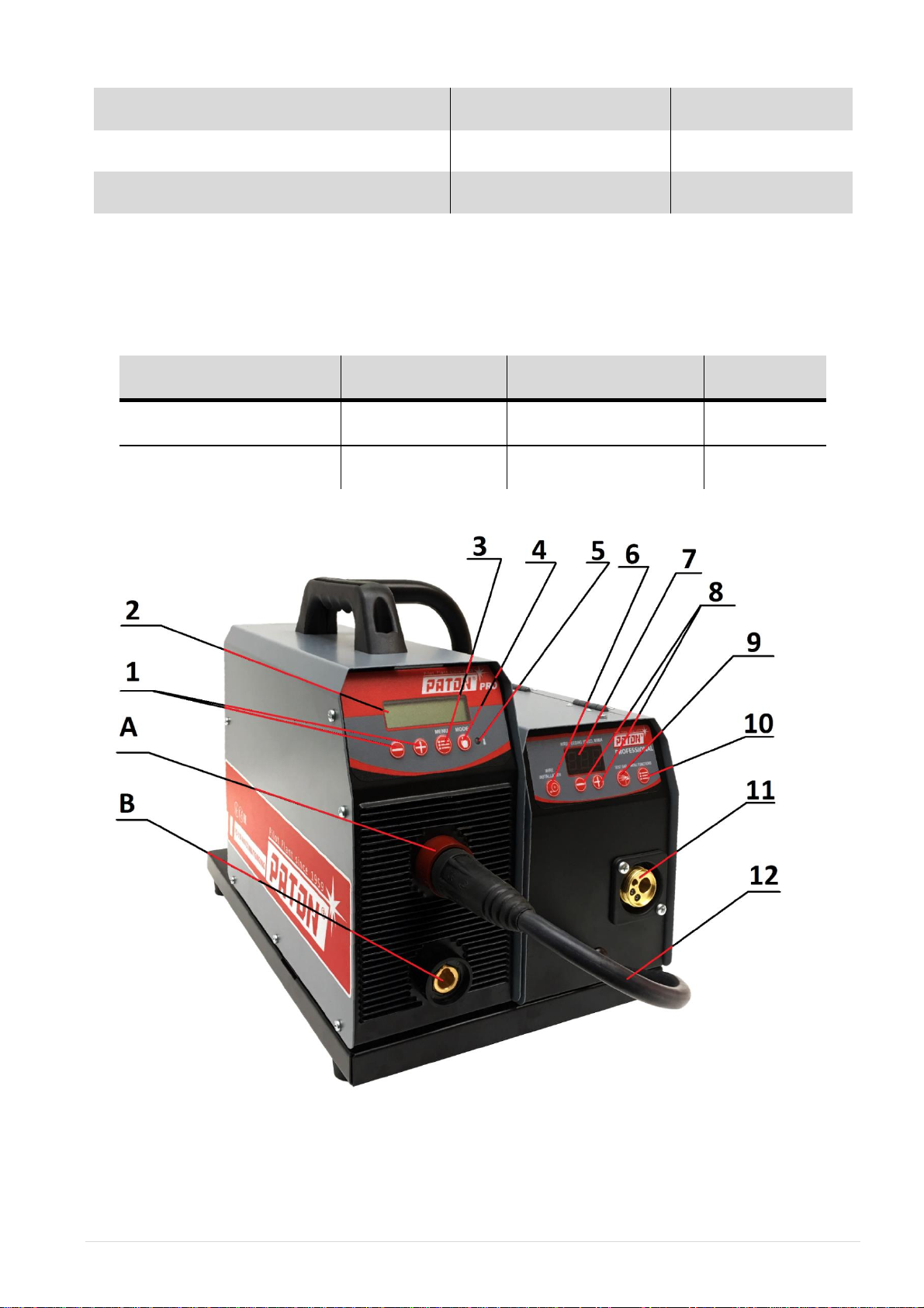
1.2. CONTROLS AND CONNECTRORS

8 | Pag e PATON®PSI PRO 270 / 350 400 V DC MIG/MAG TIG/MMA
1. Buttons for adjusting the welding current setting and parameters of the welding machine
function;
2. Digital display showing the current value and welding functions;
3. Button for adjusting the function of the selected welding method
4. Button for selecting welding method:
a) Manual covered electrode arc welding (MMA)
b) Argon arc welding with a no consumable electrode (TIG)
c) Gas shielded semiautomatic arc welding (MIG/MAG)
5. Indicator of the operating condition of the welding unit, do not light normally (blinks when
machine is overheating)
6. Button “WIRE INSTALLATION” When the button is pressed, only the wire feed is switched
on.
7. Digital display showing the wire feed speed and feeder functions,
8. Button for adjusting the wire feed speed and parameters of the feeder function
9. Button “GAS TEST” When the button is pressed, only the gas supply valve is switched on
10. Button for adjusting the function of wire feeder.

9 | Pag e PATON®PSI PRO 270 / 350 400 V DC MIG/MAG TIG/MMA
11. Euro connector socked for connecting the MIG/MAG holder
12. Polarization change cable
13. 4A and 2A fuses
14. Socket for supplying protective gas to the welding torch
15. Wire feeder inlet connector
16. Connector for supplying power to the electrode wire feeding unit from the welding unit from an
external power source
17. Push-button switch for switching on and off the welding unit
18. Power socket for 36 V gas pre-heater.
A (+) The bayonet connector socket for connecting:
a) The electrode cable (or the grounding cable in some cases when special electrodes are used
for welding) for the manual arc welding process (MMA)
b) Only the grounding cable for the argon arc welding process (TIG)
c) For welding with the "MIG/MAG" method with a solid wire - the polarization change
wire (12) is connected and the ground wire is connected to the "-" current socket.
B (-) The bayonet connector socket for connecting:
a) The grounding cable (or the electrode cable in some cases when special electrodes are used
for welding) for the manual arc welding process (MMA)
b) Only the argon gas torch for the argon arc welding process (TIG)
c) For welding with the "MIG/MAG" method with self-shield wire - the polarization change
wire is connected (12) and the ground wire is connected to the "+" current socket.
2. SETTING THE WELDING UNIT INTO OPERATION
ATTENTION!Read Section 16, "Safety instructions", before setting the
welding unit into operation.
2.1. PROPER USE
The welding unit is designed for manual covered-electrode arc welding, argon arc welding, and gas-
shielded semiautomatic arc welding. Any other use of the welding unit is considered as improper. The
manufacturer of the welding unit is not responsible for damages caused by any improper use of the
unit.
The use of the welding unit is proper if all the requirements of this Operation Manual are satisfied.
ATTENTION!Do not use the welding unit to unfreeze pipes.

10 | Pag e PATON®PSI PRO 270 / 350 400 V DC MIG/MAG TIG/MMA
2.2. REQUIREMENTS FOR INSTALLATION
The welding unit is protected against ingress of foreign particles more than 2.5 mm in size.
The welding unit is allowed for outdoor operation. The internal electrical and electronic elements of
the welding unit are protected against moisture but are not protected against atmospheric condensate
drops.
ATTENTION!After completing welding works in hot weather, or
completing intensive welding works in any weather, switch off the welding
unit only after at least 5 minutes of time required for the electronic elements of
the unit to be cooled.
ATTENTION!When operating the welding unit in cold season, after the unit
was switched off and cooled, condensate can be formed inside of the unit, so
switch on the welding unit only 3 … 4 hours after the switching off.
For this reason, do not switch off the welding unit if it is anticipated that the
unit is to be switched on not later than 4 hours after the switching off.
Install the welding unit so as not to block or cover the ventilation slots on the front and rear panels of
the unit. Prevent ingress of metallic particles (for example, when grinding the weld) sucked into the
welding unit by the unit ventilator.
ATTENTION!After fall from a height, the welding unit might be a source of
electrical shock. Install the unit on a firm stable surface.
2.3. CONNECTION TO A POWER SUPPLY SYSTEM
The commercial welding unit is rated for an input power supply voltage of 3x400 V (±15%)
ATTENTION!If the input power supply voltage of the welding unit exceeds
450 V, the warranty of the manufacturer of the welding unit will be invalid. Such
a condition is possible at large unbalance of phase voltages in the standard power
supply system or if the welding unit is connected to the power supply system
improperly. Do not use the supply system neutral wire for this purpose!!!
The power supply connector, power cable cross-section area, and supply-line fuses should be selected
with consideration for the technical characteristics of the welding unit.
2.4. REQUIREMENTS FOR AN ELECTRICAL OUTLET
ATTENTION!The parameters of an electrical outlet for the power supply of
the welding unit must correspond to the power supply voltage and consumption
current of the welding unit (see Section 1.1, "Technical characteristics"). Connect
the welding unit to an electrical outlet that is rated for a three-wire plug with a
grounding conductor.
11 | Pag e PATON®PSI PRO 270 / 350 400 V DC MIG/MAG TIG/MMA
3. MANUAL COVERED-ELECTRODE ARC WELDING PROCESS (MMA)
3.1. PREPARING THE WELDING UNIT FOR OPERATION
Preparation the welding unit for MMA operation:
1. Insert the plug of the electrode cable into socket A (+) of the welding unit.
2. Insert the plug of the grounding cable into socket B (-) of the welding unit.
3. Connect the grounding cable to the workpiece.
4. Connect the power cable of the welding unit to the outlet of the power supply system.
5. Set switch (17) on the rear panel of the welding unit to position I (switching on).
6. Switch the button (4) to the MMA welding position, if the desired welding method has been
skipped, press the button (4) again - the methods are switched over and over again
7. Holding the button (3) for about 5 seconds, we gain access to the locked functions of the
welder;
8. Using the buttons (1) set the current basic parameter - welding current or parameter of the
selected function;
9. The device is ready for use. Enjoy Your work.
If required, perform the additional functions specified for the manual arc welding process (see Section 6.1).
ATTENTION!In the manual arc welding process, after switching on the
welding unit by switch (17), the welding electrode is under voltage. Do not
allow the electrode to contact current-conducting or grounded parts, such as the
casing of the welding unit, because such a contact will cause the start of
welding.
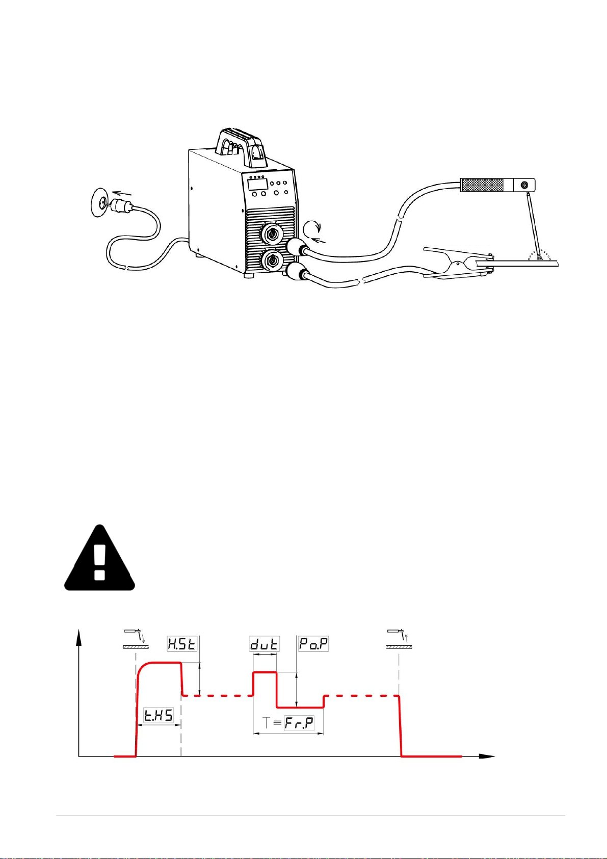
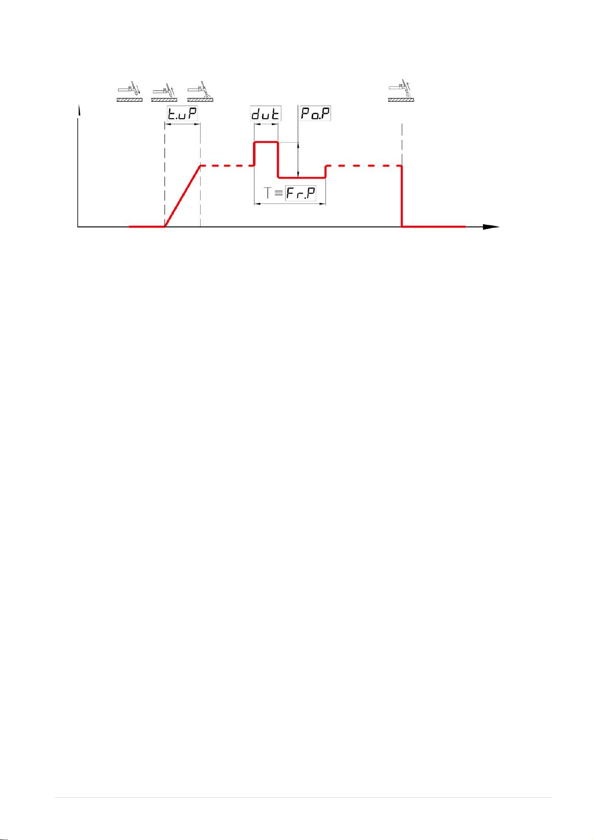
3.2. OPERATIONAL CYCLE OF THE MANUAL ARC WELDING PROCESS
The procedure for changing the values of the operational parameters of the welding unit is described in Section 6.1.
I (A)
~400 V
WORKPIECE
t (s)
ELECTRODE HOLDER
GROUNDING CLAMP

12 | Pag e PATON®PSI PRO 270 / 350 400 V DC MIG/MAG TIG/MMA
3.3. INCREASED –CURRENT ARC STARTING
The advantages ensured by the increased-current arc starting function are the following:
1. Improved arc starting even when low-quality electrodes are used
2. Better joint penetration during arc starting period and, as a result, the lower number of defects
associated with incomplete joint penetration.
3. Prevention of slag inclusions
Manual adjustment operations: allow the minimum arc starting current to be set in order to decrease
power consumption at the stage of arc starting. As a result, the welding arc can be started at the
minimum power supply voltage, but in this case, the arc quality characteristics at the stage of arc
starting are deteriorated, as the welding unit functions as an arc-welding transformer. Nevertheless, in
some conditions, this method of arc starting is the only possible one. The welding current may be
increased in order to improve the conditions for arc starting (when the welding unit is connected to a
reliable power supply system), but the increased current can cause burn-out when welding thin parts.
Therefore, it is recommended to set the minimum arc starting current.
What is achieved by:
During the short time interval of arc starting, the welding current increases by 40% of the welding
current set by default.
Example: Electrode diameter is 3 mm. Set welding current is 90 A. The current at the increased-
current arc starting stage is 90 + 40%= 126 A
The additional adjustment operations allow both the arc starting current [POWER HOT START] and
the arc staring period [TIME HOT START] to be varied. Do not set the increased values of these
parameters if such increased values are not required, because the operation of the welding unit and
reliable arc starting in these conditions are possible only if the welding unit is connected to a high-
power system.
The procedure for changing the values of the operational parameters of the welding unit for the current
welding process is described in Section 6.1.
3.4. REDUCED –VOLTAGE WELDING MODE
The advantages ensured by the reduced-voltage welding function are the following:
1. Improved arc stability in short arc welding mode
2. Improved transfer of molten metal drops into the welding pool
3. Improved arc starting
4. Reduced probability of electrode sticking (see Section 3.5)
Manual adjustment operations allow the minimum welding voltage to be set in order to decrease
power consumption and heat input to the weld when welding thin parts. As a result, the probability of
burn-out is decreased, but the stability of arc in short arc welding mode is also decreased, as the
welding unit functions as an arc-welding transformer. It is possible to increase the voltage reduction
percentage to the maximum value in order to improve the stability of arc in short arc welding mode
(when the welding unit is connected to a reliable power supply system), but the increased current in
this mode can cause burn-out when welding thin parts. Therefore, it is recommended to set the
minimum voltage reduction percentage.
13 | Pag e PATON®PSI PRO 270 / 350 400 V DC MIG/MAG TIG/MMA
How it is achieved:
When the arc voltage drop is lower than the minimum voltage required for stable arcing, the welding
current increases by 40% relative to the set current.
The additional adjustment operations allow both the welding voltage reduction percentage [POWER
ARC FORCE] and the voltage reduction period [TRESHHOLD ARC FORCE] to be set. Do not set the
increased values of these parameters if such increased values are not required, because in the operation
of the welding unit in this condition, specifically in welding with electrodes less than 3.2 mm in
diameter, electrode sticking is possible (see Section 3.5).
The procedure for changing the values of the operational parameters of the welding unit for the current
welding process is described in Section 6.1.
3.5. PROTECTION AGAINST ELECTRODE STICKING
At the stage of arc starting, the electrode can stick to the workpiece and, as a result, the electrode can
be damaged due to overheating.
If the electrode has stuck to the workpiece, the welding current decreases within 0.6 … 0.8 s after the
sticking. The temporary reduction in the welding current makes it easier for the welder to peel off the
stuck electrode. After separating the electrode from the product, the welding process can be resumed
without any problems.
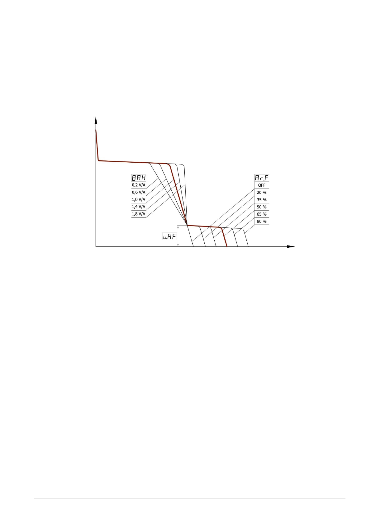
3.6 SETTING THE SLOPE OF THE VOLT-AMPERE CHARACTERISTICK OF
THE WELDING UNIT
This function is designed to facilitate welding with electrodes with diverse coatings. By default,
the slope of the volt-ampere characteristic [VOLT-AMPER CHARAKTERISTIC] of the welding unit is
1.4 V/A. This value is optimal for the most common electrodes with rutile coating. In order to facilitate
welding with electrodes with standard coating, it is recommended to set the slope of the volt-ampere
characteristic equal to 1.0 V/A. If electrodes with cellulose coating are used, the slope of the volt-
ampere characteristic should be 0.2 … 0.6 V/A. In this case, it is sometimes required to increase the
threshold value [TRESHHOLD ARC FORCE] for the reduced-voltage welding function to 18 V.
The procedure for changing the values of the operational parameters of the welding unit for the current
welding process is described in Section 6.1.
I (A)
U (V)

14 | Pag e PATON®PSI PRO 270 / 350 400 V DC MIG/MAG TIG/MMA
3.7. SHORT ARC WELDING MODE
The short arc welding mode should be used in overhead position welding, when it is required to
prevent arc stretching. For this purpose, activate (ON) the short arc welding function [SHORT ARC
MODE] of the welding unit. By default, the function is deactivated (OFF).
The procedure for changing the values of the operational parameters of the welding unit for the current
welding process is described in Section 6.1.
3.8. REDUCTION OF OPEN –CIRCUIT VOLTAGE
When welding works with the manual arc welding process are being performed on vessels, tanks, or
other objects with higher requirements for electrical safety, it is reasonable to use the reduction of
open-circuit voltage function [VOLT REDUCTION DEVICE].
When this function is activated, the output voltage of the welding unit is reduced to the safe value of
12 V within 0.1 s after the detachment of the electrode from the workpiece.
The welding unit model is equipped with this function, it requires an open-circuit voltage reduce unit
[BSn] but, by default, this function is deactivated (OFF), as the reduction of open-circuit voltage
impairs arc starting
The procedure for changing the values of the operational parameters of the welding unit for the current
welding process is described in Section 6.1.
3.9. WELDING AT PULSE WELDING CURRENT
This function is designed to simplify the control of a welding process in various spatial welding
positions, excluding a flat welding position. This function is also used in welding nonferrous metals.
When this function is activated, the application of pulse welding current improves the mixing of
molten metals in the weld area and causes forced action on the transfer of molten metal drops into the
welding pool, therefore the stability of the weld formation and the stability of the welding process are
improved. The pulse welding current in the manual arc welding process affects the weld parameters
similar to the movement of the operator hand in manual arc welding process, specifically at hard-to-
reach places. The proper adjustment of the welding process parameters in the welding at pulse
welding current has a direct effect on the weld quality, specifically reduces weld metal porosity and
decreases the graininess of the weld metal. As a result of the improved weld quality, the weld strength
increases.
To activate this function, it is necessary to set the following three operational parameters of the
welding process: current pulse amplitude [POWER OF PULSE],current pulse frequency [FREQUENCY
OF PULSE],and duty cycle [DUTY CYCLE OF PULSE]. By default, the current pulse amplitude is 0
[OFF], that is, the function is switched off, the current pulse frequency is 50 Hz, and the duty cycle is
50%. To activate the function, set the current pulse amplitude [POWER OF PULSE] higher than 0. The
current pulse amplitude should be set in percentage of the welding current specified for the welding
process.
Example: Welding is to be performed with electrode wire 3.0 mm in diameter. The set welding
current is 90 A. The current pulse amplitude is 40%. The current pulse frequency is 50
Hz (default value). The duty cycle is 50% (default value).
Result: The result is the following: the welding current pulse amplitude will be in the range of
54 … 126 A, the current pulse frequency will be 50 Hz, and the current pulse length
will be equal to the length of an interval between pulses. If the duty cycle is not equal to
50%, the current pulses will be nonsymmetrical relative to the intervals between pulses,
but the average welding current value will be equal to the set welding current value of
90 A. As a result, the average heat input to the weld will not change.

15 | Pag e PATON®PSI PRO 270 / 350 400 V DC MIG/MAG TIG/MMA
Default
[DUTY CYCLE OF PULSE]
50%
[DUTY CYCLE OF PULSE]
20%
[DUTY CYCLE OF PULSE]
70%
If it is required to reduce heat input to the weld, as in welding thin parts, the welding current should be
decreased by performing the standard setting operations. In this case, current pulse parameters will be
adjusted automatically according to the set welding current, and the operator can control the reduction
of the heat input, as compared with the heat input at the initial welding current, by simultaneously
varying the current pulse amplitude and duty cycle.
The aforementioned parameters should be set differently for different welding processes, depending on
the requirements of the operator.
Operations required to set these parameters for the current welding process are described in Section 6.1.
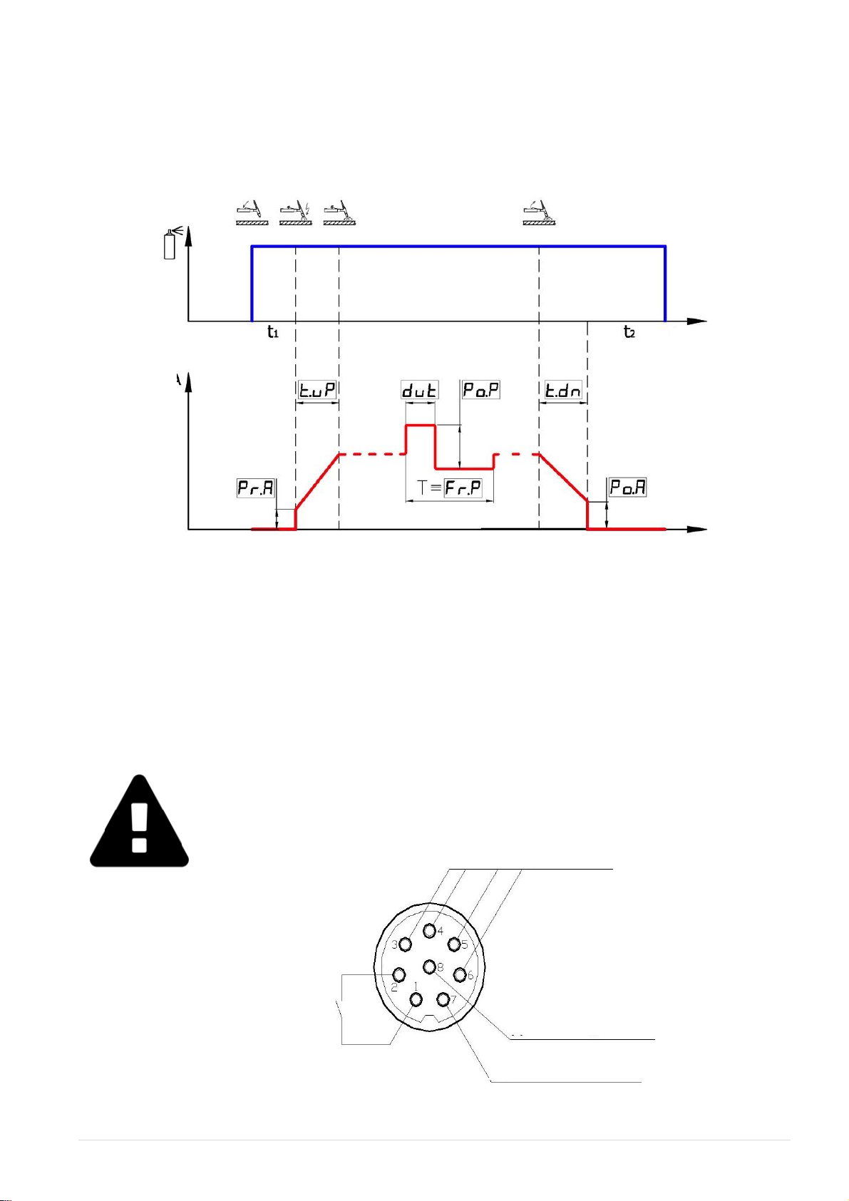
4. ARGON ARC WELDING PROCESS (TIG)
4.1. PREPARING THE WELDING UNIT FOR OPERATION TIG –LIFT
ATTENTION!As a protective gas in argon arc welding, such inert gas as
argon (Ar), sometimes helium (He), or a gas mixture, such as 40% Ar + 60%
He, is used. Do not use combustive gases. The use of other gases is allowed
only by agreement with the manufacturer of the welding unit.
t, s
t, s
WYRÓB
t, s
ARGON
WELDING
TORCH
GROUNDING CLAMP
WORKPIECE
ARGON
~ 400 V

16 | Pag e PATON®PSI PRO 270 / 350 400 V DC MIG/MAG TIG/MMA
Preparation the welding unit for TIG operation:
1. Connect the TIG torch into socket B (–)of the welding unit;
2. Connect the grounding cable into socket A (+) of the welding unit;
3. Connect the grounding cable to the workpiece;
4. Connect the power cable of the welding unit to the outlet of the power supply system;
5. Set gas reducer on gas bottle;
6. Open the shut-off valve of the gas cylinder. Check the tightness of the connection with the gas
cylinder;
7. Connect the power cable of welding unit to the outlet of the power supply system;
8. Set switch (17) on the rear panel of the welding unit to position I (switching on);
9. Switch the button (4) to the TIG welding position, if the desired welding method has been
skipped, press the button (4) again - the methods are switched over and over again;
10. Holding the button (3) for about 5 seconds, we gain access to the locked functions of the
device;
11. Press button (3) and hold it until [BUTTON OF TORCH] indication is displayed for selecting the
TIG-LIFT contact arc starting function of the button on the welding torch. When button (3) is
released, after 1 s, the display will show the value of the current function. Set value [LFT] by
buttons (1). If the TIG-LIFT contact arc starting function has been missed during the selection,
press button (3) again the methods are switched over and over again;
12. Using the buttons (1)set the current basic parameter - welding current or parameter of the
selected function;
13. The device is ready for use. Enjoy Your work.
If required, perform the additional functions specified for the argon arc welding process (see Section 6.1).
ATTENTION!Do not sharpen the electrode tip to a needle-like shape, as
such a shape can cause deviation of a welding arc from side to side. The
properly sharpened electrode tip should have a slightly blunted end with a
diameter corresponding to the specified welding current. In welding with a
large welding current, the high-sharpened electrode easily melts due to
insufficient heat dissipation. The sharpening marks should be arranged along
the electrode centerline.
ATTENTION!Use a gated welding torch with a Ф13mm bayonet connector.
Select the maximum current of the welding torch according to the
specifications.
17 | Pag e PATON®PSI PRO 270 / 350 400 V DC MIG/MAG TIG/MMA
4.2. OPERATIONAL CYCLE OF THE WELDING PROCESS TIG –LIFT
The procedure for changing the values of the operational parameters of the welding unit is described in
Section 6.1.
4.2.1. TIG-LIFT CONTACT ARC-STARTING FUNCTION
This function of the control button on the welding torch is set by default and is designed for welding
torches with contact arc starting, without using oscillators and other like devices. In contrast to
conventional methods of arc starting, the contact arc starting prevents the formation of current surge at
the instant of the arc starting. As a result, disintegration of the no consumable tungsten electrode and
ingress of the electrode particles into the weld can be prevented.
When this function has been activated, contact the electrode with the workpiece. It is allowed to hold
the electrode in this position for an unlimited length of time. When the operator is ready to welding
(for example, when the operator has lowered the protective shield and purged the weld area with gas),
it is necessary to lift the electrode tip slowly from the workpiece. The welding unit will sense this
action as a signal to start welding, and the welding current will be linearly increased to the set value.
To prevent surface melting of the electrode tip, the rate of lifting the electrode should correspond to the
set welding current value. The period [TIME UP ARC] of linear current rise is discussed in Section 4.5.
t (s)
I (A)
18 | Pag e PATON®PSI PRO 270 / 350 400 V DC MIG/MAG TIG/MMA
4.3. PREPARING THE WELDING UNIT FOR OPERATION TIG –2T
4.3.1 OPERATIONAL CYCLE OF THE WELDING PROCESS WITH TIG-2T
FUNCTION
The procedure for changing the values of the operational parameters of the welding unit is described in
Section 6.1.
The procedure for preparing the welding unit for operation with an external oscillator is an individual
one and should be described in the oscillator operation manual. The connector for remote switching on
and off the welding unit is located on the rear panel of the welding unit. Use only contacts 1 and 2 of
the connector. Do not confuse contacts 1 and 2 with contacts 3 and 4, as these contacts are designed
for powering the electrode wire feeding unit. When contacts 3 and 4 are cross-circuited, the electrode
wire feeding unit will be damaged.
ATTENTION!If this connector is not used, cover it in order to prevent
contamination.
Digital connection
(-) motor power
supply
(+) motor power
supply
I (A)
t (s)
t (s)

19 | Pag e PATON®PSI PRO 270 / 350 400 V DC MIG/MAG TIG/MMA
1. Switch on the oscillator for contactless arc starting.
2. Set switch (17) on the rear panel of the welding unit to position I (switching on).
3. Press button (4) to select the argon arc welding process (TIG). The display of the welding unit
will blink, warning the operator that the unit is ready to switch to the next welding process. If
the argon arc welding process has been missed during the selection, press button (4) again the
methods are switched over and over again;
4. Holding the button (3) for about 5 seconds, you gain access to the locked functions of the
welder;
5. Select the functions of the TIG-2T torch button. To do this, press the button (3) until the
[BUTTON OF TORCH] function appears on the display, after releasing the button for 1 second,
the device will display the current position of the function, use the (1)buttons to set [2T]. If
you do not do anything for a long time, the device will exit this function, you can go back the
same way, if the desired mode has been skipped, press the button (3) again, the functions will
switch over and over again;
6. Set the specified welding current by buttons (1).
If required, perform the additional functions specified for the argon arc welding process (see Section 6.1).
ATTENTION!Use a gated welding torch with a Ф13mm bayonet connector.
Select the maximum current of the welding torch according to the
specifications.
4.3.2 TIG-2T CONTACTLESS ARC STARTING FUNCTION
This function of the control button on the welding torch is used if the welding unit is connected to an
external module for contactless arc starting (an oscillator) with an integrated gas supply valve.
The control button on the welding torch is connected directly to the oscillator. When the control button
is pressed, the control signal is generated and transmitted to the oscillator. On this control signal
(moment of time t1), the gas supply valve will be opened for purging the weld area with gas before
welding, the welding unit will be switched on, with delay, and a high-voltage pulse for the contactless
arc starting will be generated. After these operations, all other functions, specified with consideration
for the operational cycle of this welding process, will be performed (see the sections presented below).
When the button is released, the welding current will decrease linearly, the welding unit will be
switched off (instant of time t2), and the weld area will be purged with gas. After these operations, the
gas supply valve will be closed.
ATTENTION!The oscillator must contain a device for protecting the output
of the welding unit against electric breakdown caused by a high-voltage
discharge generated at the instant of time of arc starting. Before the operation,
activate the protective device.
This manual suits for next models
1
Table of contents
Other Paton Inverter manuals


