Patriot Antenna 1.8m Offset TxRx Guide

INSTALLATION &
ASSEMBLY INSTRUCTIONS
1.8m OffsetTxRx
Antenna
ANTENNA SYSTEMS

2
This PATRIOT ANTENNA equipment is warranted to be free from defects in material and workmanship under
normal use and service. PATRIOT ANTENNA shall repair or replace defective equipment, at no charge, or at its
option, refund the purchase price, if the equipment is returned to PATRIOT ANTENNA not more than twelve (12)
months after shipment. Removal or reinstallation of equipment and its transportation shall not be at cost of PA-
TRIOT ANTENNA except PATRIOT ANTENNA shall return repaired or replaced equipment freight prepaid.
This Warranty shall not apply to equipment which has been repaired or altered in any way so as to affect its
stability or durability, or which has been subject to misuse, negligence or accident. This Warranty does not cover
equipment which has been impaired by severe weather conditions such as excessive wind, ice, storms, lightning,
or other natural occurrences over which PATRIOT ANTENNA has no control, and this Warranty shall not apply to
equipment which has been operated or installed other than in accordance with the instructions furnished by
PATRIOT ANTENNA.
Claimants under this Warranty shall present their claims along with the defective equipment to PATRIOT ANTENNA
immediately upon failure. Non-compliance with any part of this claim procedure may invalidate this warranty in
whole or in part.
THIS WARRANTY IS EXPRESSLY IN LIEU OF ALL OTHER AGREEMENTS AND WARRANTIES, ANY IMPLIED
WARRANTY OF MERCHANTABILITY OR FITNESS FOR A PARTICULAR PURPOSE IS LIMITED IN DURATION
TO THE DURATION OF THIS WARRANTY. PATRIOT ANTENNA DOES NOT AUTHORIZE ANY PERSON TO
ASSUME FOR IT THE OBLIGATIONS CONTAINED IN THIS WARRANTY AND PATRIOT ANTENNA NEITHER
ASSUMES NOR AUTHORIZES ANY REPRESENTATIVE OR OTHER PERSON TO ASSUME FOR IT ANY
OTHER LIABILITY IN CONNECTION WITH THE EQUIPMENT DELIVERED OR PROVIDED.
IN NO EVENT SHALL PATRIOT ANTENNA BE LIABLE FOR ANY LOSS OF PROFITS, LOSS OF USE, INTER-
RUPTION OF BUSINESS, OR INDIRECT, SPECIAL OR CONSEQUENTIAL DAMAGES OF ANY KIND.
In no event shall PATRIOT ANTENNA be liable for damages in an amount greater than the purchase price of the
equipment.
Some states do not allow limitations on how long an implied warranty lasts, or allow the exclusion or limitation of
incidental or consequential damages, so the above limitations or exclusions may not apply to you.
PATRIOT ANTENNA has the right to void the warranty when the antenna is installed by someone other then a
certified installer.
LIMITED TWELVE (12) MONTH WARRANTY
Patriot Antenna Systems
704North Clark Street
Albion, MI 49224 USA
Tel: (517)629-5990
Fax: (517)629-6690
E-mail: [email protected]
Product Serial Number- _________________
Date Purchased- ____________

3
Thank you for purchasing your Patriot Commercial Antenna. We trust that you will find
this to be a well designed product that will provide many years of reliable service.
This manual will help you to know the tools and proper installation of the product.
Please check, read and understand the content of this manual before beginning your
antennainstallation.
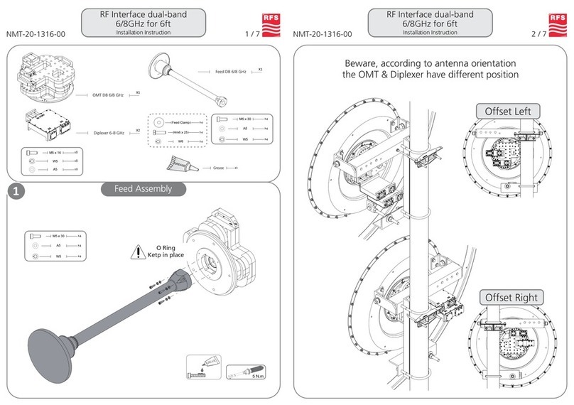
Identify and verify that all parts have been received by comparing packaged contents
with the Hardware List below.
Record the serial number of the unit on page 2 for future reference and read the
warranty information. The serial number can be found on the antenna mount.
1– Drive Socket set (7/16” through 3/4”)
1–Combinationwrench set (7/16”through3/4”)
1–1-1/8”Combinationwrench
1–1-1/2”Combinationwrench
1– 15” Adjustable wrench
No.__ Description_______ Qty_
1 Reflector assm 1
2 Back Frame Assy 1
3 Az/El Assy 1
4 Pipe Adapter Assy 1
5 Feed Support Assy 1
6 TxRx Feed System 1
No.__Description____________Qty_
7 Elev. Pivot Block 1
8 Elev.Rod 1
9 Azimuth Rod 1
10 Clevis 1
11 MountHdw Pack 1
Hardware Table
Tools Required
Requirements
1- Pre-installed4” OD Pipe(notincluded)

4
In-Ground Mast Foundation
Foundation Requirements & Specifications:
• RecommendedPad Size:40x40x24”
• Concrete: 3000 psi at 28 days, poured against undistrurbed soil
(Allow concrete 24 hour set time before installation of antenna)
• Ground the Antenna to meet applicable local Codes.
The Optional Kit Includes:
Description Qty
• 60” Steel Pipe Mast 1
18x18x1/2” Base plate with 14” centered holes
Reinforced Steel Angles for support
3-1/2” (4”O.D.) schedule 40 pipe
• 18x18”Templates 2
• 11/4x24”ThreadedRod (bolts) 4
• 1/ 1/4” Nuts, Washers 8
4 in OD
Base plate 18 x 18 x 1/2”
Use #4 rebar in all concrete pad sufaces
Placenut-washeron
thisend ofall-thread

5
Mount Assembly
Az-El assy
Pipe
Adapter
assy
Azimuth Fine
TuneRod
Elev Pivot
Block
Clevis
Assy
1. Place the Pipe Adapter Assembly on to the 4in OD ground pipe, using 1/2” x 1 1/2” bolts.
2. Attach the Az-El Assembly on to the Pipe Adapter Assembly using 1” x 5”bolt, washer, and
lockwasher.
3. Attach the Azimuth FineTune Rod as shown using 1/2”x 1 1/2”bolts,nuts, and washers.
4. Install the Elevation Pivot Block as shown using 1/2” x 1 1/2” bolts, nuts, and washers.
1/2” x 1 1/2” Bolts
(6)
1/2” x 1 1/2” Bolts
nuts, & washers (2 )
1/2” x 1 1/2” Bolts
nuts, & washers (2)
1” x 5” Bolt, Flat washer
andlockwasher

6
1. With the help of an assistant, lift the Back Frame assembly and place it onto the
Az-El assy as shown. Attach using 1” x 6” bolt, flat washer, lockwasher and nut.
2. Assemble the Elevation Rod as shown using 3/4” nuts, washers(large USS) on
each side of the elevation pivot block, and 1/2” x 1 1/2” bolts, nuts, and washers.
Back Frame to Mount assembly
BackFrame
assy
Elevation
Rod
Elevation
Pivot
Block
Az-El
assy
LargeUSS3/4”
Washers (2)
1/2” x 1 1/2” bolts, nuts,
andwashers.(2)
1”x 6”bolt, flat washer,
lockwasherand nut.

7
1.With the help of an assistant, lift Reflector assembly and place it onto the Back
Frame as shown. Use 3/8”x 1”bolts/washers to fasten. Tighten hardware after all
bolts are in place.
Reflector assembly
3/8” x1” bolts/washers (8)

8
Feed Support Assembly
1. Attach Feed Support assy to the lower tube extension of the Back frame using 1/2” x 5 1/2”
bolts, nuts and washers.
2. Assemble the Feed holder and Feed Assembly as shown using 1/4” socket head cap screw
hardware.
Feed
Support
Assy
Feed Assembly
FeedHolder
1/4”x1”Caphead
with nuts
1/2”x 5 1/2”
bolts,nuts,washers
Rx Port
Rx Port
Rx Port
Rx Port
Rx Port
Tx Port
Tx Port
Tx Port
Tx Port

9
Feed Adjustment (Polarity tuning)
Install site west Install site East
of satellite of satellite
CW CCW NorthernHemisphere
CCW CW SouthernHemisphere
FeedRotation Chart
CCW
CW
1. Adjust the Feed to the appropriate skew
angleusing the providedscalereference.
NOTE:Refer to the chart below for
polarizationangle. Elevationandpolarity are
both dependent on site azimuth and the differ-
encebetween satelliteandsite longitude.
Polarization Chart
Delta Longitude = |LONGsat - LONGsite|
0.0
10.0
20.0
30.0
40.0
50.0
60.0
70.0
80.0
90.0
0.0 10.0 20.0 30.0 40.0 50.0 60.0 70.0 80.0 90.0
Site Latitude
Polarization Angle
0
5
10
15
20
25
30
35
40
50
60
70
80
Delta
Longitude

10
The antenna assembly is now complete. To adjust the antenna toward the selected
satellite you must first know its elevation angle above horizon. Subtract 22.3 degrees
from this number and this will be the reference angle for the face of the antenna. First
tighten the Pipe Adapter assy bolts only enough to allow rotation of the mount on the
ground pipe, then using an inclinometer on the face of the antenna pre-adjust the
desired elevation angle using the 2 nuts on each side of the lower pivot block on back
of the mount. Knowing the azimuth angle of the satellite from due south roughly aim
the antenna in that direction. Peak the Azimuth on the desired Satellite and tighten
Pipe Adapter assy bolts.With the LNB connected to the proper sight-in equipment the
antenna can be accurately adjusted to the satellite signal using the threaded fine tune
adjustments on both the azimuth and the elevation.Tighten all hardware when com-
plete. Installation is complete.
Windload Information
Windload Imposed at 125 mph
Force on Front of Dish - 1,790 lbs.
Force on Back of Dish- 900 lbs.
Overturning moment- 8,950 ft.lbs.
Sighting-in Notes-

Equipment From The Industry’s Lead-
ing Satellite Equipment Manufacturer’s
Available Together - In One Place...
Weare Cal-Amp’sLARGEST
STOCKING DISTRIBUTOR!
NoLong LeadTimes...
No Drop Ship Fees...
High Inventory...
Great Prices...
Complete line of Quality Feedhorns,
Receivers and Accessories - from a
name you trust
W e A l s o O f f e r P r o d u c t s f r o m t h e f o l l o w i n g :
Durable Snow Covers for Commercial
Antennas as well as Home System -
Keep snow from interfering with your
signal.
Prevent Snow & Ice from accumlulating
on your system with a De-Icing System. Complete line of Antenna Controllers,
Positioners and Software for your
motorized applications.
Looking to increase your
satellite’s reception? Try
upgrading your feed
system to a Multi-Beam
Feed. Receive up to 4
simultaneous satellites
Products Also Avaliable from:
Offset VSAT
& DBS Antennas Available!
•
ADL• General Instruments
• Baird • Norsat
• Drake • Standard Comm
• DX • Thomson-Saginaw
• Force • Wegner
Toll Free 1-800-470-3510
11

Specifications
Electrical
Gain(11.95Ghz) 45.6dBi
Efficiency 70%
NoiseTemp.(30degreeelev) 21K
3dBBeamwidth .97Deg
Avg 1st Side Lobe -23dB
CrossPolarization -30dB
VSWR(max) 1.3:1
Mechanical
AntennaSize 1.8m
Offset Angle 22.3
F/D .62
OperationalWind 50mph
SurvivalWind 125mph
OperationalTemp -40 to 140 F
Rain Operational=1/2in./hr
Survival = 3in./hr
Ice 1in. Radial -or-
1/2 in. + 60mph wind
Pole Size 4”OD
12
Rev 04-03
ANTENNA SYSTEMS
704 North Clark Street
Albion, MI 49224 USA
Tel: (517)629-5990
Fax: (517)629-6690
E-mail: [email protected]
Web site: www.sepatriot.com
Table of contents
Other Patriot Antenna Antenna manuals


