Havequestions? Call
800-USA-1-USA
(800-872-1872)orvisitourwebsiteatwww.ritron.com
!! CAUTIONS — ALL RADIOS !!
page7
OBSERVE CAUTION IN THE FOLLOWING
ENVIRONMENTS TO MAXIMIZE THE LIFE OF
YOUR RADIO EQUIPMENT:
MOISTURE: SST Series radios are not waterproof.
DO NOT directly expose them to rain or excessive
moisture.
CHEMICALS: Detergents, alcohol, aerosol sprays or
petroleum products can damage the radio case. DO
NOT use petroleum solvents of any kind; use a soft
cloth moistened with water to clean the case.
EXTREME HEAT: High temperatures can damage the
battery and other components. DO NOT expose the
units to extreme heat or leave them in direct
sunlight.
LOW TEMPERATURES: The capacity of the NiCd
battery is greatly reduced in extreme cold. When
using the unit in very cold environments, periodically
warm the radio under your coat.
EXCESSIVE TRANSMISSIONS: Maximum drain on
battery power occurs when you are transmitting.
DO NOT hold the Push-To-Talk switch down longer
than necessary during transmission intervals. DO
NOT reduce battery service life by attempting to
power a radio with a depleted battery; always
charge batteries overnight after each day of use.
VIBRATION/ SHOCK: Although your SST Series
radio is designed to be rugged, it will not survive
excessive abuse. Avoid dropping the radio.
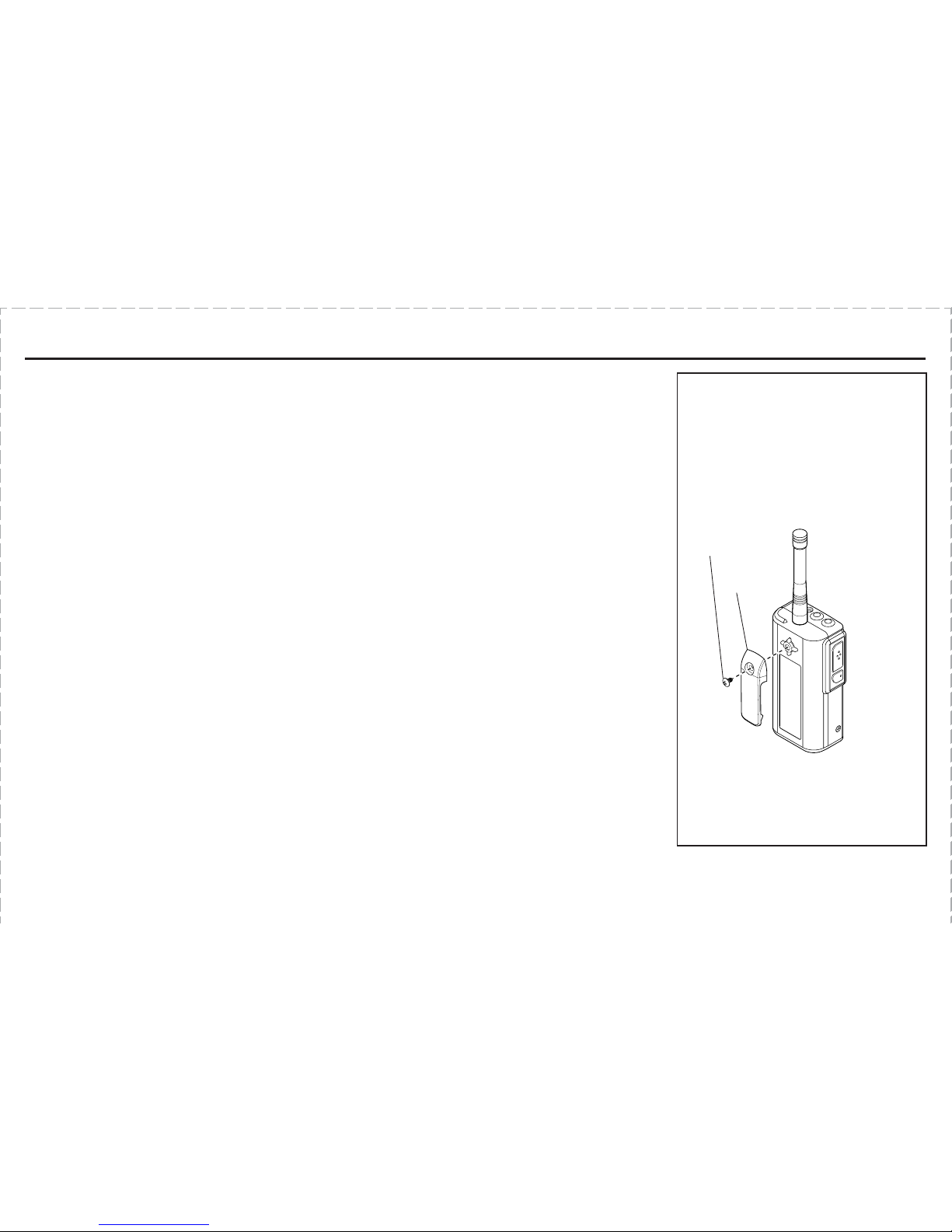
NOTE: The optional MH-A holster provides added
protection from weather and shock.
The JMX/SST Series handheld radios generate RF
electromagnetic energy during transmit mode. The
transmit mode is active when the PTT switch is
depressed. This radio is designed for, and classified
as, “Occupational Use Only”, meaning that it must be
used only during the course of employment by
individuals who are aware of the hazards and the
ways to minimize such hazards. This series of
radios is NOT intended for use by the “General
Population” in an uncontrolled environment.
When used as directed, this series of radios is
designed to comply with the FCC’s RF exposure limits
for “Occupational Use Only”. In addition, they are
designed to comply with the following Standards and
Guidelines:
• FCC OET Bulletin 65, Edition 97-01, Supplement C,
Evaluating Compliance with FCC Guidelines for
Human Exposure to Radio Frequency Electromag-
netic Fields.
• American National Standards Institute (C95.1-
1992), IEEE Standard for Safety Levels with
Respect to Human Exposure to Radio Frequency
Electromagnetic Fields, 3 kHz to 300 GHz.
• American National Standards Institute (C95.3-
1992), IEEE Recommended Practice for the
Measurement of Potentially Hazardous Electro-
magnetic Fields-RF and Microwave.
To ensure that exposure to RF electromagnetic
energy is within the FCC allowable limits for occupa-
tional use, always adhere to the following guidelines:
• Use only the antenna(s) available from RITRON
for these models. DO NOT attempt to substitute
any other antenna. DO NOT operate the radio
without an antenna.
• Keep talk times as short and infrequent as
possible. DO NOT depress the PTT button when
not actually wishing to transmit. These radios are
equipped with an internal timer to limit continuous
transmit times. DO NOT exceed a 50% transmit
duty cycle.
• When transmitting, hold the radio in front of the
mouth at a distance of at least 4 inches. DO NOT
hold the radio in such a manner that the antenna
is next to, or touching, exposed parts of the
body, especially the face or eyes while transmit-
ting.
• In belt mounted applications, when transmitting,
remove the radio from the belt and hold away
from the body at least 4 inches.
• When using external headset accessories, hold
the unit away from the body at least 4 inches
while transmitting.
•DO NOT allow children to operate the radio.
EXPOSURE TO RADIO FREQUENCY ENERGY