pauly CPV1038 01 Series User manual

Fotoelektrik Pauly –Light barriers
E_52692 Ref. 2019-29 1/24
Fotoelektrik Pauly GmbH, Wahrbrink 6, D-59368 Werne, T: +49 2389/402 27-70, F: +49 2389/402 27-77
http://www.fotoelektrik-pauly.de, eMail: info@fotoelektrik-pauly.de
pauly
Operating instructions
Optical Anti-Collision Device
TypeCPV1038
E_52692.pdf
Features
Functionalities
Cat. 2, PL=c, SIL 1
in acc. with EN ISO 13849 and
EN 62061
Two optical systems in one
enclosure
Two adjustable independent
clearance distances
Clearance distance up to 50 m
High performance in terms of
detection
Pollution warning/ Anti Sabotage
system
Integrated test system –a highly
dynamic process reproduces the
light reflected by the reflector
Safe mounting of reflectors
oCollision protection
oDistance monitoring
Only for cranes that run on a common crane
track or rail.
Revision Index: 2019-29
Revision date: 12.04.2019
Processed by: tb

Fotoelektrik Pauly –Light barriers
E_52692 Ref. 2019-29 2/24
Fotoelektrik Pauly GmbH, Wahrbrink 6, D-59368 Werne, T: +49 2389/402 27-70, F: +49 2389/402 27-77
http://www.fotoelektrik-pauly.de, eMail: info@fotoelektrik-pauly.de
Table of Contents
1. Identification / General Remarks 3
1.1 Product versions / Plates representations 3
1.2 Name and address of the manufacturer 3
1.3 Applied standards and technical specifications: 4
1.4 Definition of symbols: 4
2. Product description 4
2.1 Product mark 4
2.2 Intended use, general function and area of application 5
2.3 Incorrect use and foreseeable misuse 5
2.4 Safety information 6
3. Definitions –technical data 7
4. Operating instructions 9
4.1 Information on this technical description 9
4.2 Device description 9
4.3 Description of function 10
4.3.1 Triangulation triangle 10
4.3.2 Approach movement 11
4.3.3 Continually self-testing 12
4.3.4 Possible movement of the crane 12
4.3.5 Movement of the crane is stopped 12
4.4 Pollution control function 13
4.4.1 Principle 13
4.4.2 Pollution example 13
4.4.3 Pollution Indicator –meaning of the different circuit states 14
4.5 Assembly 15
4.5.1 Horizontal arrangement of the triangulation triangle 15
4.5.2 Distance monitoring accuracy 16
4.5.3 Taking the tolerances into consideration with respect to clearance distance 17
4.6 Information on assembly 18
4.7 Adjustment using the “light beam method” 19
4.8 Electrical connection 20
4.9 Applicable documents 22
5. Maintenance and cleaning 22
6. Contents of the EU Declaration of Conformity 23
7. Decommissioning 24
8. Spare parts 24
Fotoelektrik Pauly –Light barriers
E_52692 Ref. 2019-29 3/24
Fotoelektrik Pauly GmbH, Wahrbrink 6, D-59368 Werne, T: +49 2389/402 27-70, F: +49 2389/402 27-77
http://www.fotoelektrik-pauly.de, eMail: info@fotoelektrik-pauly.de
1. Identification / General Remarks
1.1 Product versions / Plates representations
CPV1038
CPV1038*01
Bezeichnung
General description
Optical Anti-Collision Device
Typ
Type
CPV1038
CPV1038 /R/2M20/i/… 5269x…
0393
Seriennummer
Serial number
Baujahr
Year of manufacture
Reichweite
Range
0,5…25/50m
Versorgung
Supply
Schutzart
Protection mode
IP65
Reaktionszeit
Response time
80ms
Fotoelektrik Pauly
59368 Werne / Germany
www.fotoelektrik-pauly.de
Bescheinigungsnummer
Certificate number
HSM 09 079
Sicherheits-Integritätslevel
Safety Integrity Level
1
gemäß DIN EN 62061
according to DIN EN 62061
Sicherheitskategorie
Safety category
2
Performance
Level
c
MTTFd[a]
86
gemäß DIN EN ISO 13849-1
according to DIN EN ISO 13849 -1
Bezeichnung
General description
Optical Anti-Collision Device
Typ
Type
CPV1038*01
CPV1038*01 /R/2M20/i/… 5269M01x…
0393
Seriennummer
Serial number
Baujahr
Year of manufacture
Reichweite
Range
1…25m
Versorgung
Supply
Schutzart
Protection mode
IP65
Reaktionszeit
Response time
80ms
Fotoelektrik Pauly
59368 Werne / Germany
www.fotoelektrik-pauly.de
Bescheinigungsnummer
Certificate number
HSM 09 079
Sicherheits-Integritätslevel
Safety Integrity Level
1
gemäß DIN EN 62061
according to DIN EN 62061
Sicherheitskategorie
Safety category
2
Performance
Level
c
MTTFd[a]
86
gemäß DIN EN ISO 13849-1
according to DIN EN ISO 13849 -1
1.2 Name and address of the manufacturer
Fotoelektrik Pauly GmbH
Wahrbrink 6
59368 Werne, Germany
Fotoelektrik Pauly –Light barriers
E_52692 Ref. 2019-29 4/24
Fotoelektrik Pauly GmbH, Wahrbrink 6, D-59368 Werne, T: +49 2389/402 27-70, F: +49 2389/402 27-77
http://www.fotoelektrik-pauly.de, eMail: info@fotoelektrik-pauly.de
1.3 Applied standards and technical specifications:
EN ISO 13849
Safety of machinery –Safety-Related Parts of Control
Systems
EN 62061
Safety of machinery - Functional safety of safety-related
electrical, electronic and programmable electronic control
systems
1.4 Definition of symbols:
Must follow –Critical information
This symbol describes safety warning of dangerous situations and indicates
necessary measures and / or appropriate precautionary measures.
Failure to comply can result in death or property damage.
Must know –Important information
This symbol describes e.g. situations that could damage the product or
devices in its vicinity, and accordingly provide appropriate action.
The sign identifies particularly important passages.
2. Product description
2.1 Product mark
CPV1038 und CPV1038*01: high performance reflex light barriers for distance monitoring tasks
using the triangulation method.

Fotoelektrik Pauly –Light barriers
E_52692 Ref. 2019-29 5/24
Fotoelektrik Pauly GmbH, Wahrbrink 6, D-59368 Werne, T: +49 2389/402 27-70, F: +49 2389/402 27-77
http://www.fotoelektrik-pauly.de, eMail: info@fotoelektrik-pauly.de
2.2 Intended use, general function and area of application
Acknowledgement of the contents of these operating instructions forms part of the intended use.
Notes and safety information must be observed in particular.
The Model CPV1038 System is
a mechanism for collision protection or distance monitoring exclusively for stationary power
driven cranes that run on a common crane track. The reflector centre on the other crane must
be situated at the optical device (lens) level.
intended for use in weatherproof applications where the direct influence of the weather is
prevented
exclusively intended for use in machinery within the meaning of the scope of EN 60204-32
(Electrical Equipment of Cranes), EN 15011 (Bridge and gantry cranes) and EN 12077-2
(Limiting devices).
When used as collision protection device, the moving crane is prevented from colliding e.g. brought
to a standstill in reference to the other crane (opposite crane).
When used as a distance monitoring device, a risk triggering approach of cranes is detected.
At least one device is required for each crane and the corresponding reflector is positioned at the
opposite wall/crane.
2.3 Incorrect use and foreseeable misuse
It is not permissible to use the device in any manner that deviates from the contents of the
operating instructions or operate it outside the prescribed areas of application.
The CPV1038 is not suitable for operation in
areas with significant challenging environmental requirements (e. g. potentially explosive
areas).
areas of excessive pollution influence where a proper function may not be ensured, despite
regular cleaning of the optical elements.
applications where normal operation due to excessive fog, excessive steam or excessive
smoke cannot be guaranteed.
systems where disconnecting the current does not lead to a safe mode.
collision protection and distance monitoring for cranes which run on a curved crane/rail track.
collision protection and distance monitoring for cranes which do not run on a common
crane/rail track.
collision protection of e.g. Industrial trucks or similar transport equipment.
use without reflector (please refer section 3)
Any technical alteration will result in cancellation of the product warranty!

Fotoelektrik Pauly –Light barriers
E_52692 Ref. 2019-29 6/24
Fotoelektrik Pauly GmbH, Wahrbrink 6, D-59368 Werne, T: +49 2389/402 27-70, F: +49 2389/402 27-77
http://www.fotoelektrik-pauly.de, eMail: info@fotoelektrik-pauly.de
2.4 Safety information
System-related movement tolerances of crane system components and the possible
associated effects on the switching behaviour of the distance monitoring system
must be taken into consideration when planning crane systems.
A correct assembly and alignment of the system are essential for the correct
operation of the system’s safety function.
The set clearance distance could be reduced, e.g. by fog, steam or smoke.
During limited vision, e.g. caused by fog, steam or smoke, the function of the
distance monitoring system must be checked by moving the cranes together.
The light beam on the system must not be interrupted, for example by obstructions
or suspended objects. It is essential that proper attention is paid to this during
assembly and operation of the system.
Before commencement of work, the system’s safety function must be checked by
moving the cranes together (daily functional check).
The installation of the light barriers may only be performed by authorized technical
personnel who have the requisite professional expertise to install electrical devices on
crane systems.
The device must be immediately taken out of operation in the event of damage or leaks in
the housing, cable or line entries.
Requirements resulting from provisions relating to cranes must be applied under all
circumstances.
All different components with safety functions must be taken into account of the safety
parameters (PL, PFHd, MTTFd), e.g. an optionally required additional external power supply
or output side follow-up circuit.
Further or supplementary protective measures may be required on the basis of risk
assessments for special areas of application, e.g. restart inhibit. According to
EN ISO 13849, an automatic restart may only take place, if no hazardous situation exists.
The distancing system may not be bridged.
The crane operator and/or the crane manufacturer must be aware and comply to the
information that applies to his area of deployment; this also applies to the product, cables
and lines installation
If condensation on the reflector surface cannot be excluded for an application with high air
humidity or/and abrupt change in temperature then an anti-fogging coated reflector version
must be used. A suitable reflector type will be model 4R100BLAF or model 18R100BLAF
(see catalog of applicable documents in section 4.9).
If the device is operated in conjunction with other components such as control systems or
sensors, the corresponding user instructions must be heeded.
Fotoelektrik Pauly –Light barriers
E_52692 Ref. 2019-29 7/24
Fotoelektrik Pauly GmbH, Wahrbrink 6, D-59368 Werne, T: +49 2389/402 27-70, F: +49 2389/402 27-77
http://www.fotoelektrik-pauly.de, eMail: info@fotoelektrik-pauly.de
3. Definitions –technical data
CPV1038
CPV1038*01
Certificate no.
HSM 09 079
Safety ratings of complete system
in acc. with EN 62061 respectively
EN ISO 13849-1
Safety Integrity Level (SIL)
SIL 1 in acc. with
EN 62061
Performance Level (PL)
PL c in acc. with
EN ISO 13849-1
Category
Cat. 2 in acc. with
EN ISO 13849-1
DC [%]:
60 in acc. With
EN ISO 13849-1
Safety ratings of the electronic
device
in acc. with EN ISO 13849-1
PFHd[h-1]:
6,61 x 10⁻⁷
MTTFd[a]:
86
nop [n/a]
8760
CCF
95
Mission time TM[a]
20
Maximum clearance distance
50 m
25 m
Optical systems
2
Safety-related tolerance of the
systematically distancing
accuracy
Maximum 9%
(in accordance with diagram fig. 4.4.3)
Safety-related tolerance of the
distancing accuracy due to
environmental influences
Additional 8%
(by reason of environmental influences,
e.g. fog, steam, smoke)
Power supply / output or current
consumption
(: Option)
230VAC ± 10 %
/ 16VA
115VAC ± 10 %
/ 16VA
42…48VAC ± 10 %
/ 16VA
24VDC + 20 % / - 10 %
/ ~ 700mA
Connection
2 x cable glands; terminal strip
Switching outputs
Main contact (to switch off the
crane movement)
for each optical system: 2 x relay NO contacts;
supervised and force guided
Status message
for each optical system: 1 x relay NC contact
Pollution warning
1 x relay change-over contact

Fotoelektrik Pauly –Light barriers
E_52692 Ref. 2019-29 8/24
Fotoelektrik Pauly GmbH, Wahrbrink 6, D-59368 Werne, T: +49 2389/402 27-70, F: +49 2389/402 27-77
http://www.fotoelektrik-pauly.de, eMail: info@fotoelektrik-pauly.de
CPV1038
CPV1038*01
Switching capacity
Min. switching current
10 mA @ > 5 V
Main contact (to switch off the
travel movement)
AC1: 5 A @ 230 VAC DC1: 6 A @ 24 VDC
AC15: 2 A @ 230 VAC DC13: 1 A @ 24 VDC
Status message
AC1: 5 A @ 230 VAC DC1: 6 A @ 24 VDC
AC15: 1 A @ 230 VAC DC13: 1 A @ 24 VDC
Pollution warning
AC1: 6 A @ 250 VAC DC1: 6 A @ 24 VDC
AC15: 2 A @ 250 VAC DC131: 1 A @ 24 VDC
Electrcal life
DC1: > 1 x 10⁶@ max. switching capacity
AC1, AC15, DC13:> 2 x 10⁵@ max. switching capacity
Switching rate
3 / s
Access time
≤80 ms
Switching displays
Switch indicator
for each optical system: 2 x LED green
Level indicator (for sighting
reflector)
for each optical system: 4 x LED red (DIANA)
Transmitted light
850 … 880 nm, invisible
Steady light resistance
> 80 k lux
Operating mode
Alternating light, dynamic, continually self-testing
Signal mode
Dark switching
Housing
Cast aluminum
Protection mode
IP65 –protection against dust and jets of water
Weight
~ 5000 g (without adjustment flange)
Operating temperature
- 25 °C … + 60 °C, non-condensing
Climatic conditions
in acc. with EN 60721-3-3:1995, table 1
max. relative humidity (d): 95%;
max. solar radiation (j): 700W/m²;
Condensation (m): none;
Wind-driven precipitation (n): none;
Formation of ice and frost (including freeze-thaw) (p): none
Special functions
Exterior test system
The safety-related switching outputs will be switched off and
the movement of the crane will be halted if there is
insufficient detection capacity
Sabotage protection
Covering of light barriers is detected and will lead to the
switching off of the safety-related switching outputs and the
crane movement will be halted
Pollution warning
The light signal level is evaluated continuously
Accessories
Reflectors
(intended use as per the clearance distance)
4R100BL
0.5 … 25 m
1 … 25 m
4R100BLAF
0.5 … 25 m
1 … 25 m
18R100BL
0.5 … 50 m
1 … 25 m
18R100BLAF
0.5 … 50 m
1 … 25 m
Adjustment flange
JF57S
Regarding CPV1038*01: Device without optical sensing behaviour in range 1 to 6 m.
1
With spark suppressor only, see Section Fehler! Verweisquelle konnte nicht gefunden werden.

Fotoelektrik Pauly –Light barriers
E_52692 Ref. 2019-29 9/24
Fotoelektrik Pauly GmbH, Wahrbrink 6, D-59368 Werne, T: +49 2389/402 27-70, F: +49 2389/402 27-77
http://www.fotoelektrik-pauly.de, eMail: info@fotoelektrik-pauly.de
4. Operating instructions
4.1 Information on this technical description
These operating instructions contain information on the correct use of the CPV1038 distance
monitoring system. They constitute an integral part in the scope of supply.
4.2 Device description
A distance monitoring system or collision protection system consists of a reflex light barrier and a
reflector. The CPV1038 distancing system sets two definite clearance distances separately from
each other. Each individual clearance distance is set in accordance with the triangulation principle.
The electronics for the reflex light barrier system are housed in an enclosure with IP 65 protection.
A protection roof protects the lens system of the reflex light barrier against external conditions, for
example rain, snow or dust. The protection roof is fixed on the enclosure lid. For opening the lid,
the protection roof can be folded up.
An adjustment flange is available for mounting the reflex light barrier. This enables fast and
accurate assembly and alignment.
There are two optical systems in the enclosure. The two optical systems can be set to different
clearance distances independently of each other. Each individual clearance is set by means of a
system-specific spindle axle.
Each system is assigned its own external test unit. The external test units generate continually
defined light signals (infra-red light), which impact on the internal receiving unit through the
receiving lens. The external test units continuously simulate the light reflected by a reflector.
A highly dynamic signal processing procedure evaluates the rays of light pulses received. This
evaluation means that the distance monitoring system is fail-safe, shock resistant, resistant to
external light and stable.
When the set clearance distance is reached, the reflector on the opposite crane can be viewed.
The view of the reflector and any internal component faults decisively alter the dynamic signal
processing and accordingly slow down or stop the crane’s movement. When farther clearance
distance is reached, the crane’s speed is slowed down. Once the nearer clearance distance is
reached, the crane completely stops (safe state).
Each system of the reflex light barrier continuously performs tests on its function using the highly
dynamic signal processing procedure –“continually self-testing”. Any worsening in visibility
conditions or direct pollution of the lenses leads to weakening of the signal. Significantly weakened
signals that could substantially impair the function are detected at an early stage and directly lead
to the stopping of the crane (safe state).
The high optical performance of the system means the distance monitoring system can be used for
distances up to 50 m and still have very considerable reserves in terms of function.
Travel movement can be halted if the light barrier is made “blind” due to the lens being covered
over at close range –“sabotage protection”.
The integrated signal-emitting pollution evaluation is effective for the current reflector view and
evaluates the current signal level. If the signal level on the active reflector view is too low the
pollution is displayed via a signalling contact.

Fotoelektrik Pauly –Light barriers
E_52692 Ref. 2019-29 10/24
Fotoelektrik Pauly GmbH, Wahrbrink 6, D-59368 Werne, T: +49 2389/402 27-70, F: +49 2389/402 27-77
http://www.fotoelektrik-pauly.de, eMail: info@fotoelektrik-pauly.de
The requisite reflector plates on the reverse are available in different sizes. The format to be used
for the reflector is determined by the clearance distance and the resultant triangulation angle.
For clearance distance
reflector area (width x height)
Model
up to 25 m
400 mm x 100 mm
4R100BL(AF)
up to 50 m
900 mm x 200 mm
18R100BL(AF)
The reflector comprises a carrier plate with individually mounted reflector elements on it. The
reflector elements are fastened with screw connections that cannot be loosened with conventional
tools. Moreover, due to their design, the reflector elements cannot get be misplaced. The special
design of the reflector plate means that the reflector elements are protected against strong
pollution deposits and overflowing water. It is not possible to dismantle the reflector using
conventional tools without damaging it.
4.3 Description of function
4.3.1 Triangulation triangle
The clearance distance is determined using the
triangulation method. For this purpose, the high
performance reflex light barrier must be aligned at an
angle to the direction of movement of the crane
towards the reflector affixed to the other crane. The
right-angled triangulation triangle is formed as
follows: (when sighted from the light barrier)
from the distance between the two cranes –
connecting line between the installation location
of the light barrier and the left reflector
edge = adjacent side to angle >< and
from the width of the reflector = opposite leg to
the angle >< and
from the outer light cone form the reflex light
barrier = hypotenuse of the right-angled triangle.
Fig.: 4.3.1
Triangulation triangle
Reflex-light barrier
Crane 2
Crane 1
Reflector

Fotoelektrik Pauly –Light barriers
E_52692 Ref. 2019-29 11/24
Fotoelektrik Pauly GmbH, Wahrbrink 6, D-59368 Werne, T: +49 2389/402 27-70, F: +49 2389/402 27-77
http://www.fotoelektrik-pauly.de, eMail: info@fotoelektrik-pauly.de
4.3.2 Approach movement
The reflex light barrier illuminates the edge of the
reflector during the approach movement, when the
set clearance distance is reached. The first system in
the reflex light barrier sights the reflector. The
switching outputs of the first system of the reflex light
barrier are switched off –pre-disconnection.
If the approach is continued and the second set
clearance distance is reached, the second reflex light
barrier illuminates the edge of the reflector. The
switching outputs of the second system in the reflex
light barrier are switched off.
The safety-related switching outputs
switched off and crane travel is
brought to a halt! The cranes stops
with a safe distance from each other.
Fig.: 4.3.2-1
Fig.: 4.3.2-2
The level of the light signal depends on the degree of coverage by the light spot of the reflex light
barrier on the reflector. Even very small amounts of cover lead to very high signal levels. This
results in a signal level with extremely steep edges.
Crane 2
Crane 1
Attention
Crane 2
Crane 1

Fotoelektrik Pauly –Light barriers
E_52692 Ref. 2019-29 12/24
Fotoelektrik Pauly GmbH, Wahrbrink 6, D-59368 Werne, T: +49 2389/402 27-70, F: +49 2389/402 27-77
http://www.fotoelektrik-pauly.de, eMail: info@fotoelektrik-pauly.de
4.3.3 Continually self-testing
During the entire operation the light reflected by the reflector is reproduced by each external test
unit. Each external test unit generates a modulated light signal and shines through the receiver
lens and onto the own receiver. The modulated test signal received is evaluated by the highly
dynamic signal processing procedure. In this manner, a functional check of all optical and
electronic construction elements is conducted simultaneously. The light barriers performs self-tests
continuously.
If the reflector is not sighted and if no optical or electronic faults are present, the NO contact of two
separate and mutually monitored switching relays for releasing the travel movement are switched
on. The design has resulted in relays that are specially qualified. Positively driven contacts here
ensure a high degree of reliability. The power via the contacts has to be limited by an overcurrent
protection device.
4.3.4 Possible movement of the crane
Prerequisite: The reflector is undetected. The actual distance between the cranes is greater than
the set clearance distances. The beams of the reflex light barriers goes past the reflector. There
are no optical or electronic faults.
Effect: The crane is cleared for movement. For each system, two safety-related relays are switched
on and these signal the clearance for crane movement through the closed NO contacts. 2 green
status LEDs are switched on directly with the relays and visualize the clearance for crane travel.
4.3.5 Movement of the crane is stopped
Prerequisite: The set clearance distance is reached during the approach travel. The reflector edge
of the other crane moves into the beam of the first or second system of the reflex light barrier.
Effect: The reflex light barrier detects its emitted light signal and switches the system associated
two safety-related relays off. The green status LEDs darken. The travel movement is stopped.
REMARK:
Switching off the safety-related relays, depending on the task, can be used either to reduce the
speed or stop the travel movement.
In accordance with its purpose, the two systems serves to influence the cranes movement by
means of a pre-disconnection and a main disconnection.
Once the first distance has been reached, the pre-disconnection typically slows down the crane
movement while the crane movement is stopped once the main disconnection is reached.

Fotoelektrik Pauly –Light barriers
E_52692 Ref. 2019-29 13/24
Fotoelektrik Pauly GmbH, Wahrbrink 6, D-59368 Werne, T: +49 2389/402 27-70, F: +49 2389/402 27-77
http://www.fotoelektrik-pauly.de, eMail: info@fotoelektrik-pauly.de
4.4 Pollution control function
4.4.1 Principle
Primarily, the photoelectric barrier monitors itself continuously, independent of the travel
movements. The light signal level, which is sent from the external test unit through the receiver
lens, is evaluated at all times. The weakening of a specific signal level due to contamination of this
test device (see also example in section 4.4.2) leads initially to a pollution warning signal. If the
pollution is not eliminated, and with the increasing pollution, the specific function signal is further
weakened then this leads to the stopping of the travel movement and the safety-related switching
relays is switched off.
In a secondary effect, the reflector signal level is evaluated with active reflector detection. The
weakening of a specific signal level here also leads to a pollution warning signal.
The pollution on the external test unit of the light barrier will be much more sensitively evaluated
than the pollution on the reflector.
The pollution warning signal is displayed with the “VK-relay”. The triggered relay means that there
is a pollution which must be eliminated as soon as possible, where the location of the pollution
should be derived from the circuit states of the VK-relay and the states of the safety-related relays
(see also section 4.4.3).
4.4.2 Pollution example
Dust precipitation on an external test unit which can
lead to a Pollution warning signal and/or blocking of
the system.
In case of cleaning of the reflex light barrier system,
the pollution of lenses, external test unit and the
reflector are to be particularly eliminated
For the cleaning procedure, please note in addition
the chapter 5 on “Maintenance and cleaning” of the
respective operating instructions.
Fig.: 4.4.2
An appropriate warning system should be triggered by the pollution warning relay to
provide timely detection and removal of pollution to maintain system availability.
Fotoelektrik Pauly –Light barriers
E_52692 Ref. 2019-29 14/24
Fotoelektrik Pauly GmbH, Wahrbrink 6, D-59368 Werne, T: +49 2389/402 27-70, F: +49 2389/402 27-77
http://www.fotoelektrik-pauly.de, eMail: info@fotoelektrik-pauly.de
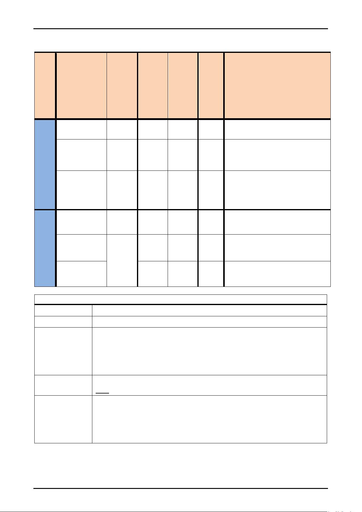
4.4.3 Pollution Indicator –meaning of the different circuit states
Table: 4.4.3
Drive action
Specific signal
level external test
unit
Specific signal
level reflector
view
Pre-switching
safety-related
relay, circuit state
Main-switching
safety-related
relay, circuit state
VK-relay circuit
state
Meaning
Distance travel without
reflector view
Higher than
V-level
-
on
on
off
No pollution on LB
Less than
V-level, but
higher than
switch-off level
-
on
on
on
Pollution on LB –Prompt
cleaning of light barrier and
reflector required!
Less than
switch-off level
-
off
off
on
Severe pollution on LB with
transition into the secure status
(stopping of the travel movement)
–Immediate cleaning of light
barrier and reflector required!
Approach travel with
reflector view
-
Higher
than
V-level
off
on
off
No pollution on the reflector
-
Less
than
V-level
off
on
on
Pollution on the reflector OR
incomplete reflector view in the
pre-switching mode
-
off
off
on
Pollution on the reflector OR
incomplete reflector view in the
main switch-off mode
Legend / Explanations
V-level
Pollution warning level (default setting by manufacturer)
LB
Light barrier
Pollution on the
reflector
The Pollutants on the reflector has to be assumed if the limit distance has
been reached and the corresponding safety-related relays switched off, AND
after switching off the safety-related relays a sufficiently large distance has
been driven which should generates a larger reflector signal level than the
specific V-level itself.
Incomplete
reflector view
A permanently very small reflector view with signal level less than V-level
BUT signal level high enough to stop the travel movement.
Pollution Control
signal
The pollution warning signal is displayed with a relay (VK). The relay is
switched on with a delay of approx. 3s up to 5s if the current signal level
does not exceed the specific V-level during this period.
The pollution warning signal is reset immediately if the current signal level
exceeds the V-level again.

Fotoelektrik Pauly –Light barriers
E_52692 Ref. 2019-29 15/24
Fotoelektrik Pauly GmbH, Wahrbrink 6, D-59368 Werne, T: +49 2389/402 27-70, F: +49 2389/402 27-77
http://www.fotoelektrik-pauly.de, eMail: info@fotoelektrik-pauly.de
4.5 Assembly
4.5.1 Horizontal arrangement of the triangulation triangle
Reflector () and light barrier-CPV1038 ()
are mounted horizontally. The triangulation
triangle () then lies in the space horizontally.
is mounted onto the crane using the JF57S
adjustment flange. An imaginary line () that
runs parallel to the crane track () connects
on the right edge of the reflector (). The
angle () of the triangulation triangle should
be selected such that the is pointing
towards the left reflector edge when the limit
distance is reached () (see also chapter on
“adjustment”).
The triangulation triangles must be designed in such a way that the light barrier optics do not
look into each other, directly or via reflections. Examples:
Fig.: 4.5.1-2:
Proper arrangement
Fig.: 4.5.1-3:
Proper arrangement
Fig.: 4.5.1-4:
Wrong arrangement
Fig.: 4.5.1-5:
Wrong arrangement
Note to fig. 4.5 1-3: The distance between the applied outer edge of the device and the reflector
must be at least 200mm.
The Reflector and CPV1038 must be mounted
at the same height. This means that the
middle of the reflector () must be positioned
at the same height () as the middle of the
lens system of CPV1038 (). The height of
both parts should be taken from a common
reference point ().
It is essential to ensure that both optical systems can still view the reflector when both
cranes have been moved together up to buffer distance!
Mount the reflector close to the edge of the crane bridge. Avoid blocking the visible area
of the reflector.
Fig.: 4.5.1-1: Example of a triangulation triangle
clamped to the left
Fig.: 4.5.1-6
Fotoelektrik Pauly –Light barriers
E_52692 Ref. 2019-29 16/24
Fotoelektrik Pauly GmbH, Wahrbrink 6, D-59368 Werne, T: +49 2389/402 27-70, F: +49 2389/402 27-77
http://www.fotoelektrik-pauly.de, eMail: info@fotoelektrik-pauly.de
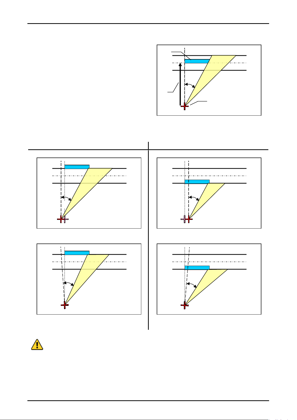
4.5.2 Distance monitoring accuracy
The clearance distance () is determined by
the fixed beam angle set (). The accuracy
and the reproducibility of the clearance
distance depend on the movement tolerances
of the individual crane components. Horizontal
lateral shifts or rotations of the crane bridges
have a direct impact on the installation position
of the reflex light barrier () or the reflector ()
and accordingly shorten or lengthen the
clearance distance set.
Lengthening the clearance distance
Shortening the clearance distance
System-related movement tolerances in crane systems, crane/rail track and the
associated impact on the switching behaviour of the distance monitoring system should
be taken into consideration at the planning stage for the crane system and crane/rail
track.
Fig.: 4.5.2-1: Set clearance distance
Fig.: 4.5.2-2: Shifting to the left
Fig.: 4.5.2-3: Shifting to the right
Fig.: 4.5.2-4: Rotation to the left
Fig.: 4.5.2-5: Rotation to the right

Fotoelektrik Pauly –Light barriers
E_52692 Ref. 2019-29 17/24
Fotoelektrik Pauly GmbH, Wahrbrink 6, D-59368 Werne, T: +49 2389/402 27-70, F: +49 2389/402 27-77
http://www.fotoelektrik-pauly.de, eMail: info@fotoelektrik-pauly.de
4.5.3 Taking the tolerances into consideration with respect to clearance distance
The very high performance of the system facilitates “tolerant” functional behaviour. However a
certain tolerance in terms of distance behaviour must be taken into account for the very reason of
this high performance in order for perfect, planned functional behaviour of the system to be
guaranteed at all times in the long term (e.g. aging). For this reason the following possible
tolerances must be taken into consideration from the start.
Fig.: 4.5.3: Tolerance in relation to the triangulation angle
The safety-related tolerances in the distances accuracy must be taken into account by
adding them to the planned clearance distance.
In case of applications with environmental influences, e.g. excessive fog, excessive
steam or excessive smoke, additionally 8% of the planned clearance distance must be
considered
Case example with and without environmental influences:
Planned distancing = 15 m
Reflector width = 400 mm (crane reflector 4R100BL)
Calculated triangulation angle 1.5°
Tolerance in accordance with diagram fig. 4.5.3: 7% ≙1,1 m
Additional tolerance because of environmental influences: 8% ≙1,2 m
Minimum distancing to be set
without environmental influences = 16.1 m + movement tolerance.
with environmental influences = 17,3 m + movement tolerance.
Deviation in % from the
clearance distance
Triangulation angle in degrees

Fotoelektrik Pauly –Light barriers
E_52692 Ref. 2019-29 18/24
Fotoelektrik Pauly GmbH, Wahrbrink 6, D-59368 Werne, T: +49 2389/402 27-70, F: +49 2389/402 27-77
http://www.fotoelektrik-pauly.de, eMail: info@fotoelektrik-pauly.de
4.6 Information on assembly
The mounting has to be done in such a way that a misalignment caused by
mechanical vibration or bumps can be excluded. After finishing the fine alignment,
the transducer benches have to be tightened with the fixing screws.
The adjustment flange has to be locked with the mounting surface. Drill a hole of
6mm diameter and 20mm length close to each fastening hole and pin the
adjustment flange with the enclosed spring dowel sleeves.
The reflector must be installed in non-accessible areas or must be concealed.
The reflector should be protected from pollution by suitable measures e.g. a
protective housing.
The light beams of the systems must not be interrupted e.g. obstructions or
suspended objects. This must be taken into account at all events during assembly
and operation of the system.
It is to be absolutely ensured that the optics of the distancing assembly still has a
reflector view if both cranes have driven together to buffer separation distance!
When calculating the clearance distance the reaction time of the system must be
taken into consideration as decisive parameter for the stopping path of the crane.
The set clearance distance must be tested and recorded.
The reflector centre on the other crane must be situated at the optical device (lens) level
(see Fig. 4.5.1.6).
The devices on a crane and the adjacent crane must be mounted in such a way that their
optical system do not look into each other (directly or via reflections), Any mutual
influence must be excluded (see Fig.: 4.5.1-2…-5).
In contrast to the assembly location of the reflector, assembly of the light barrier
(optoelectronics) must take place at the site where more pollution is to be expected.
The fixture of the CPV on the associated adjustment flange must be done by means of
the provided fasteners.
The fastening of the reflector must take place using rivets, adhesive or welded
connectors or using the screws supplied (safety screws with locking wedge),so that
dismantling can only take place by destroying the fastening element.
During and after the adjustment, it must be ensured that the plastic (safety) inserted part
of the lock nut engages on the thread and the springs are pretensioned.
Assembly may only be performed by a trained professional.
Triangulation angle Δ≥1° to be set, see graph Fig.: 4.5.3: Tolerance in relation to the
triangulation angle

Fotoelektrik Pauly –Light barriers
E_52692 Ref. 2019-29 19/24
Fotoelektrik Pauly GmbH, Wahrbrink 6, D-59368 Werne, T: +49 2389/402 27-70, F: +49 2389/402 27-77
http://www.fotoelektrik-pauly.de, eMail: info@fotoelektrik-pauly.de
4.7 Adjustment using the “light beam method”
Both cranes are moved together to the limit
distance (). For the adjustment the end of
the reflector () is illuminated with a portable
spotlight () placed close to the optical unit.
With the lid of the device open, it is possible to
detect the reflection of the brightly illuminated
reflector () on the transducer bench of the
reflex light barrier ().
With the lid of the device closed, the reflector
image can be observed from outside through
the lens of the reflex light barrier using a
special adjustment help ().
The vertical adjustment of the light barrier is
set by means of the adjusting screw (). The
center of the reflector image should be
adjusted to the height of the transmitter and
receiver diode converter holes.
The slotted mounting (and ) can be used
to rotate the device at the horizontal level.
Separately accessible spindle drives –behind
the dummy screw () –can be used to set
each individual optical system separately to a
definite distancing range.
Graphical representation of the reflector image
() on the transducer bench () during the
adjustment procedure using the “light beam
method”.
The light barrier is able to sight the reflector
when the edge of the light image falls into the
transmitter hole () or receiver hole ().
If the light images of the reflector move in a
straight line and horizontally across the
transducer bench during the further approach
travel, then the triangulation triangle is
clamped absolutely horizontally. The dividing
wall () prevents an optical short-circuit
between transmitter and receiver.
See also the separate document „Setting Instructions CPV1038“
Fig.: 4.7-3
Fig.: 4.7-1
Fig.: 4.7-2
Fig.: 4.7-4: Representation of the reflector image
for a triangulation angle clamped to the right.

Fotoelektrik Pauly –Light barriers
E_52692 Ref. 2019-29 20/24
Fotoelektrik Pauly GmbH, Wahrbrink 6, D-59368 Werne, T: +49 2389/402 27-70, F: +49 2389/402 27-77
http://www.fotoelektrik-pauly.de, eMail: info@fotoelektrik-pauly.de
4.8 Electrical connection
Fig.: 4.8: Connection diagram CPV1038
Table 4.8
Terminal block
Naming
Function
1
L1 / +24V DC
Supply voltage Version ‘AC’: L1
Version ‘DC’: + 24 V
2
N / 0V
Supply voltage Version ‘AC’: N
Version ‘DC’: 0 V
PE
PE
Protective earth conductor
3 & 4
NO11
Make contact 1 (normally open contact) of system 1,
safety-related
5 & 6
NC11||NC12
Break contact of system 1
7 & 8
NO12
Make contact 2 (normally open contact) of system 1,
safety-related
9 … 11
NOv/COMv/NCv
Pollution warning changeover contact
12 & 13
NO21
Make contact 1 (normally open contact) of system 2,
safety-related
14 & 15
NC21||NC22
Break contact of system 2
16 & 17
NO22
Make contact 2 (normally open contact) of system 2,
safety-related
This manual suits for next models
1
Table of contents
Other pauly Lighting Equipment manuals


