Pavone Sistemi UWT6008 User manual
Pavone Sistemi
pesatura elettronica industriale
TECHNICAL MANUAL
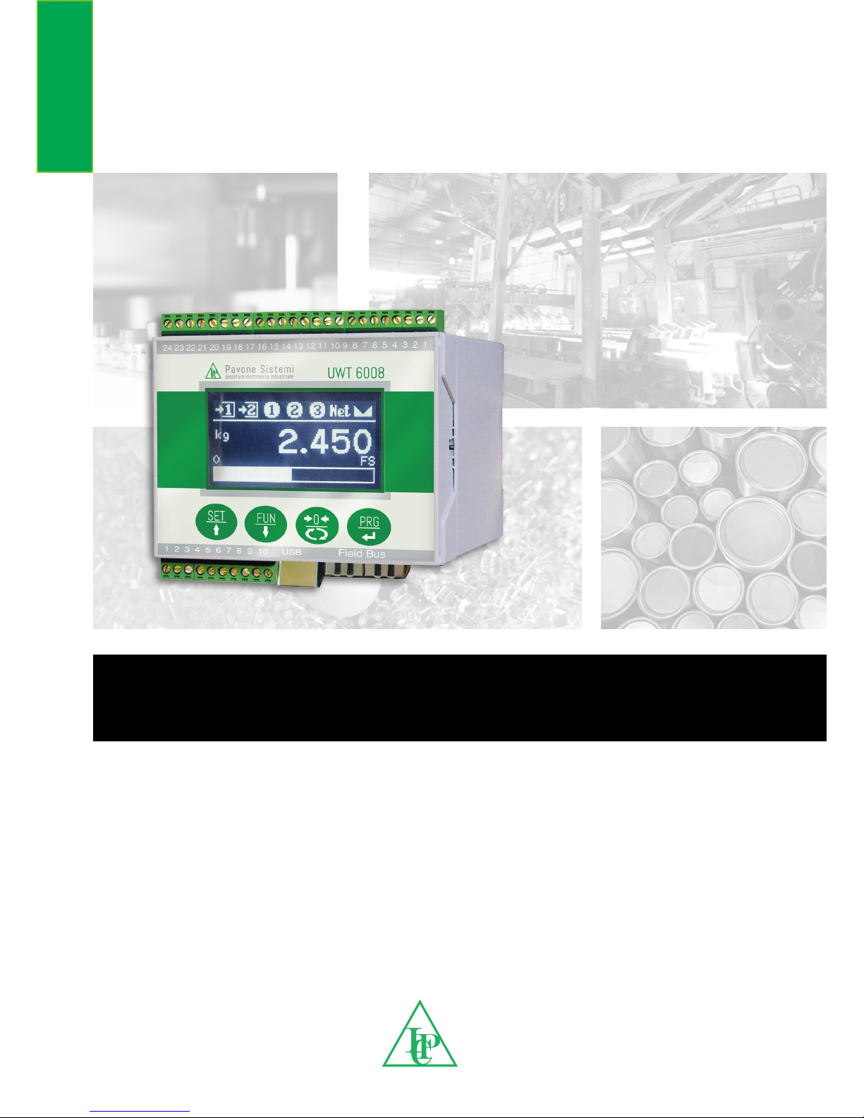
UWT6008 / JBX8 LCD Electronic weighing instrument
Program P32001 Rel.0.0

Rel ID 18280501
TABLE OF CONTENTS
TECHNICAL FEATURES.......................................................................................................... 3
CONNECTIONS, POWER SUPPLY, SERIAL ITEMS, USB, FIELD BUS ............................................ 4
CONNECTIONS, LOAD CELLS, OUTPUTS............................................................................... 5
INTRODUCTION .................................................................................................................. 6
FRONT PANEL OF THE DEVICE .............................................................................................. 7
KEYBOARD USE ................................................................................................................... 7
PROGRAMMING MENU ....................................................................................................... 10
CALIBRATION SETTINGS....................................................................................................... 13
LOAD CELLS BALANCING..................................................................................................... 14
WEIGHT CALIBRATION......................................................................................................... 15
ANALOG OUTPUT SETTINGS ................................................................................................ 16
SERIAL PORTS – RS232 SETTINGS.......................................................................................... 17
SERIAL PORTS – RS485 SETTINGS.......................................................................................... 17
SERIAL PORTS SETTINGS - ETHERCAT CONFIGURATION.......................................................... 18
SERIAL PORTS SETTINGS - PROFIBUS CONFIGURATION .......................................................... 19
SERIAL PORTS SETTINGS - PROFINET CONFIGURATION .......................................................... 19
SERIAL PORTS SETTINGS - ETHERNET/IP CONFIGURATION ..................................................... 20
SERIAL PORTS SETTINGS - CANOPEN CONFIGURATION ........................................................ 21
SERIAL PORTS SETTINGS - ETHERNET CONFIGURATION.......................................................... 21
I/O SETTINGS...................................................................................................................... 22
SETTING THE WEIGHTING PARAMETERS ............................................................................... 23
FILTER SETTINGS................................................................................................................... 24
FUNCTIONAL FEATURES SETTINGS........................................................................................ 25
DATE CLOCK ADJUSTMENT ................................................................................................. 27
ACCESS DISPLAY.................................................................................................................. 27
CONSULTATION OF FISCAL MEMORY ................................................................................... 28
OPERATING FUNCTIONS - CELL SIMULATION......................................................................... 28
OPERATING FUNCTIONS - SINGLE CELLS DISPLAY .................................................................. 28
LOAD CELLS EMULATION...................................................................................................... 29
OPERATING FUNCTIONS - THRESHOLD PROGRAMMING ....................................................... 30
OPERATING FUNCTIONS - STORING THE MEASURE............................................................... 30
SERIAL COMMUNICATION PROTOCOLS ............................................................................... 31
MODBUS COMMUNICATION PROTOCOLS ........................................................................... 36
FIELDBUS COMMUNICATION PROTOCOLS............................................................................ 39
CANOPEN COMMUNICATION PROTOCOLS......................................................................... 43

TECHNICAL FEATURES
Transducers power supply: 5 VCC (max. 16 cells of overall 350 Ohm)
Measuring range: -3.9 ÷ +3.9 mV/V
Input sensitivity: Min. 0.02 μV
Linearity: < 0.01% FS
Thermal drift: < 0.001% FS/ °C
Display: 128 x 64-pixel graphic LCD
A/D converter: 24 bits
Internal resolution: > of 16,000,000 points
Signal capture frequency: 12 ÷ 1000 Hz
Displayable resolution: 999,999 divisions viewable on the net weight
Divisions value (selectable): x1, x2, x5, x10, x20, x50
Settable decimals: 0.0; 0.00; 0.000; 0.0000
Filter: selectable 0.1 to 250 Hz
Keyboard: 4-button membrane
Device power supply: 12÷24 Vdc ± 15% - power consumption 4 W
Operating temperature: -10/+ 50°C (max. humidity: 85% without conden-
sation)
Storage temperature: -20/+70°C
Logical outputs: 2 relays, Max. 48 VAC/VCC, 2A each
Logical inputs: 2 opto-isolated at 12/24 VDC PNP (external power
supply)
Serial ports: 1 USB device + 1 RS232C + 1 RS485
Field bus: ETHERNET 10/100 with TCP, MODUBUS/TCP, UDP,
IP, ICMP, ARP; PROFIBUS DP; DEVICENET; PROFINET;
ETHERNET/IP; CANOPEN; ETHERCAT protocols
Optional analog output: 16-bit opto-isolated Voltage: 0 ÷ 5/10 V (min. R: 10
K Ohm), Current: 0/4 ÷ 20 mA (max. R: 300 Ohm).
Analog output calibration: From the keyboard
Analog output linearity: < 0.02% FS
Analog output thermal drift: 0,001% FS/°C
Microcontroller: ARM Cortex M0+ at 32 bits, 256KB Flash repro-
grammable on-board from USB
Data memory: 64 Kbytes expandable up to 1024 Kbytes.
Compliance with regulations: EN61000-6-2, EN61000-6-3 for EMC; EN61010-1
for Electrical Safety, EN45501 for metrology
Electric connections: Removable screw terminal boards, 3.81 mm pitch
Dimensions: 100 x 75 x 110 mm (L x H x P)
Mounting type: On DIN rail
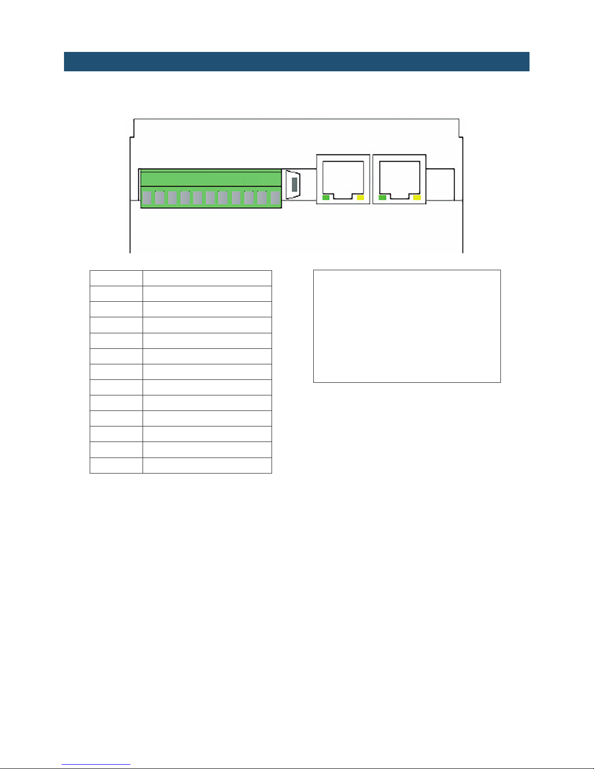
CONNECTIONS, POWER SUPPLY, SERIAL ITEMS, USB, FIELD
BUS
NUM Terminal board 3.81 mm
1 + Input 1
2+ Inlet 2
3 - Common items to inputs
4 Rs485 +
5 Rs485 -
1 TX RS232
2 RX RS232
3 GND + Serial screens
9 + 24 VDC power supply
10 - GND power supply
USB
Field bus
ETHERNET 10/100 with TCP,
MODUBUS/TCP, UDP, IP, ICMP, ARP;
PROFIBUS DP; DEVICENET;
PROFINET; ETHERNET/IP;
CANOPEN; ETHERCAT protocols
1 11
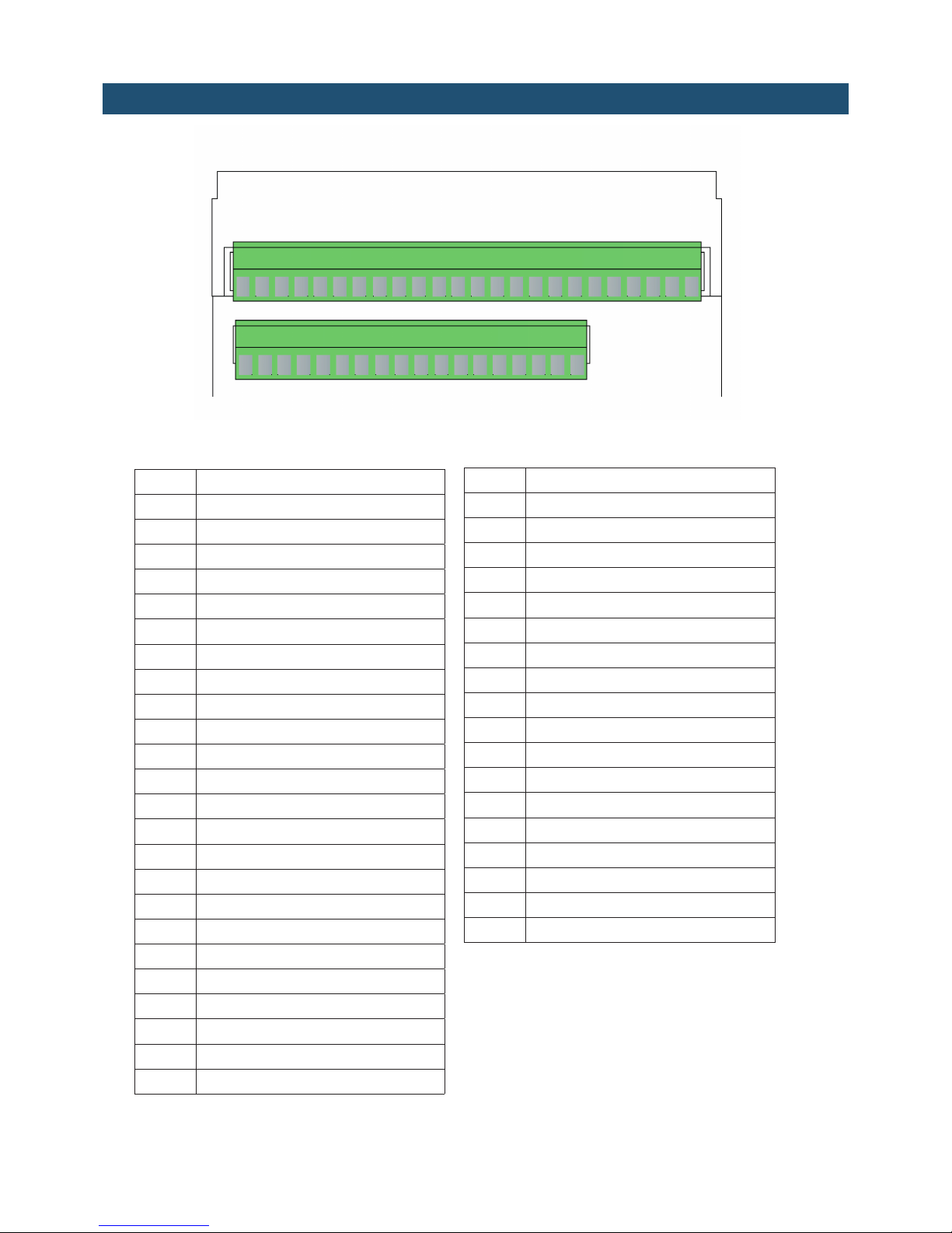
CONNECTIONS, LOAD CELLS, OUTPUTS
NUM Upper 3.81 mm terminal board
1 Cell 1 Power supply +
2 Cell 1 Signal +
3 Cell 1 Signal -
4 Cell 1 Power supply -
5 Cell 2 Power supply +
6 Cell 2 Signal +
7 Cell 2 Signal -
8 Cell 2 Power supply -
9 Reference +
10 Reference -
11 Cell 3 Power supply +
12 Cell 3 Signal +
13 Cell 3 Signal -
14 Cell 3 Power supply -
15 Cell 4 Power supply +
16 Cell 4 Signal +
17 Cell 4 Signal -
18 Cell 4 Power supply -
19 TX RS232
20 RX RS232
21 Serial GND
22 + Analog output mA
23 + Analog output V
24 - Analog output
If the cells used are 4-wire, make a jumper between Power supply + and Reference +, and between
Power supply - and Reference -.
NUM Lower 3.81 mm terminal board
25 Cell 5 Power supply +
26 Cell 5 Signal +
27 Cell 5 Signal -
28 Cell 5 Power supply -
29 Cell 6 Power supply +
30 Cell 6 Signal +
31 Cell 6 Signal -
32 Cell 6 Power supply -
33 Reference +
34 Reference -
35 Cell 7 Power supply +
36 Cell 7 Signal +
37 Cell 7 Signal -
38 Cell 7 Power supply -
39 Cell 8 Power supply +
40 Cell 8 Signal +
41 Cell 8 Signal -
42 Cell 8 Power supply -
124
25 42
INTRODUCTION
The device is a precision transmitter, the result of the most recent and advanced technology
for weighing and measuring systems of load cells. The device allows to display analog cells
separately (up to a maximum of 8 cells).
The device converts the mV signal of the load cells into a high resolution digital signal (24 bits)
for each individual cell; the sum of the points will therefore give more precise information on
the weight value captured.
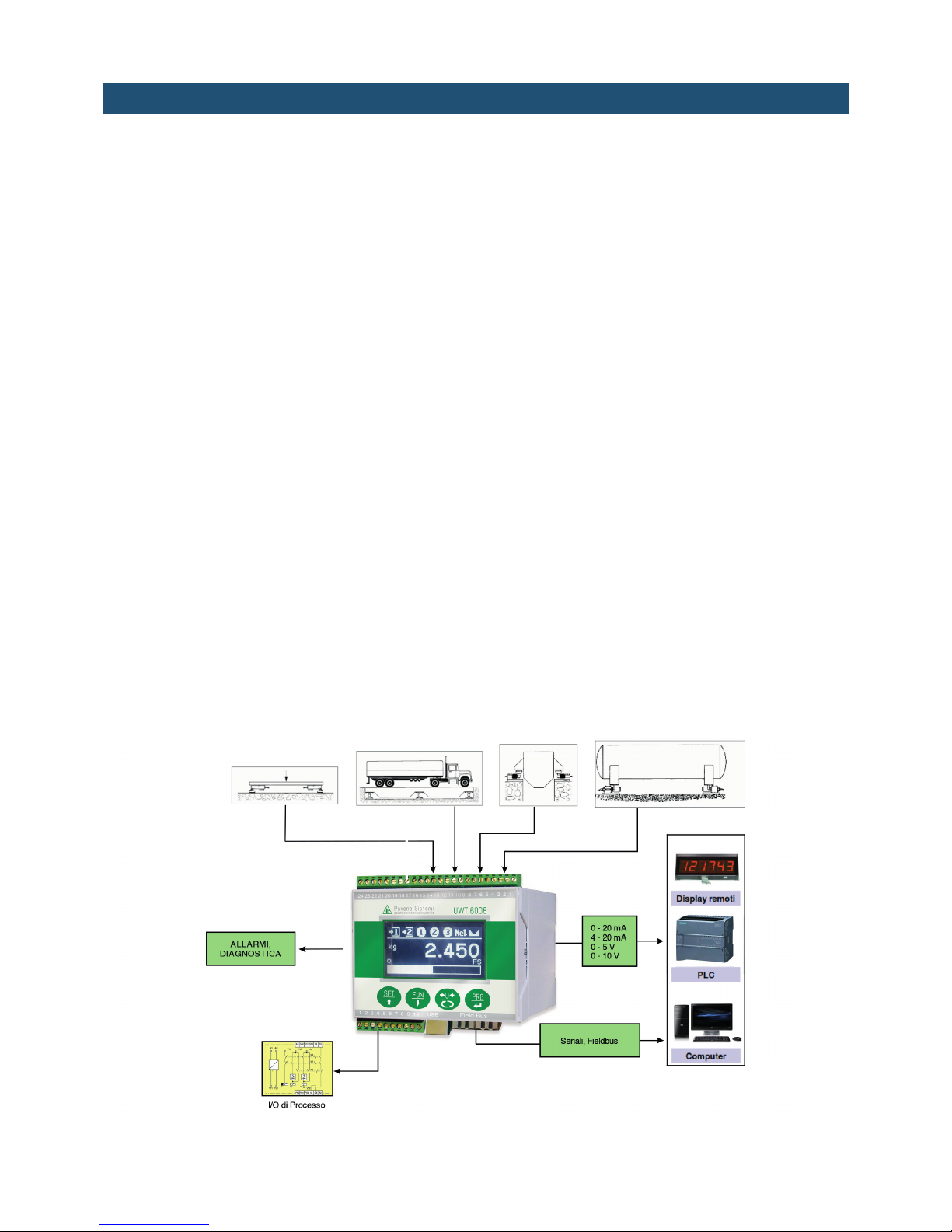
The transmitter can be integrated as a slave in different network types, through various Serial
or Fieldbus communication protocols.
The common analog load cells are connected to the transmitter, instead of the expensive digital
cells. The combination provides the following advantages:
1.Independent display of the output in mV/V and of the weight value of each individual
cell.
2.Monitoring of all load cells and alarm generation for excessive cell signal drifts,
missing connections, failure of one of the cells, unbalanced weight distribution.
3.The emulative control allows the continuity of work of the weighing system even in case
of failure on one of the load cells, up to repair or replacement.
4.The equalization function automatically compensates for the differences between the
weight values detected by the load cells during the start of the scale.
5.A particular algorithm allows to equalize the corners of the scale with only 1 passage
of the sample weight (instead of the numerous steps required by the traditional
procedure with multi-turn trimmer).
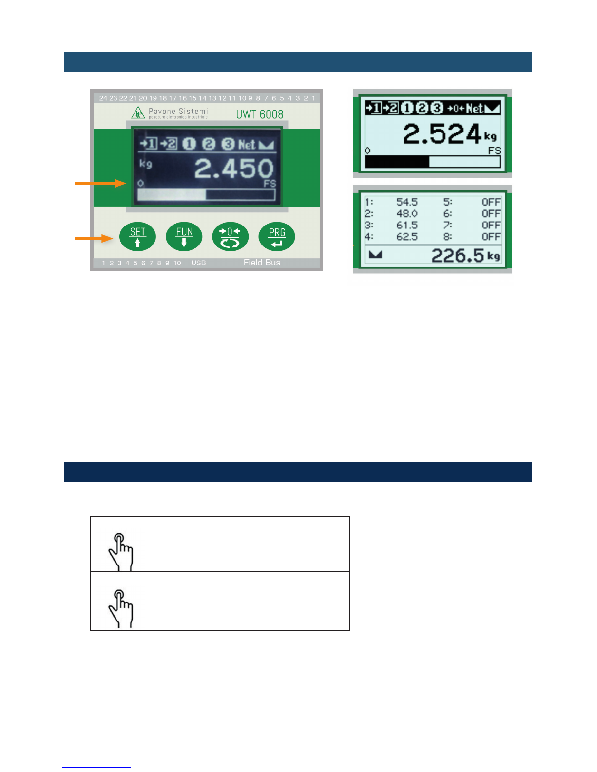
FRONT PANEL OF THE DEVICE
LCD DISPLAY
Normally the measured net weight is shown on the display. According to the various
programming procedures, the display is used for programming the parameters to be entered
in the memory, i.e. messages indicating the type of operation being carried out and therefore
helping the operator in the management and programming of the device.
STANDBY FUNCTION
The display can assume standby status, during which the brightness of the display is reduced
and the keypad is locked. All other functions of the device are ON and working.
See the paragraph concerning the activation/deactivation of the standby status.
KEYBOARD USE
The device is programmed and controlled through the mechanical keyboard consisting of 4 keys,
having the following functions:
Short press on the single button. The buzzer
will release a short sound.
Long press on the single button. The buzzer
will release a short sound when pressed and
a long sound after 2 seconds.
The use of the keyboard in the different standard procedures is described below.
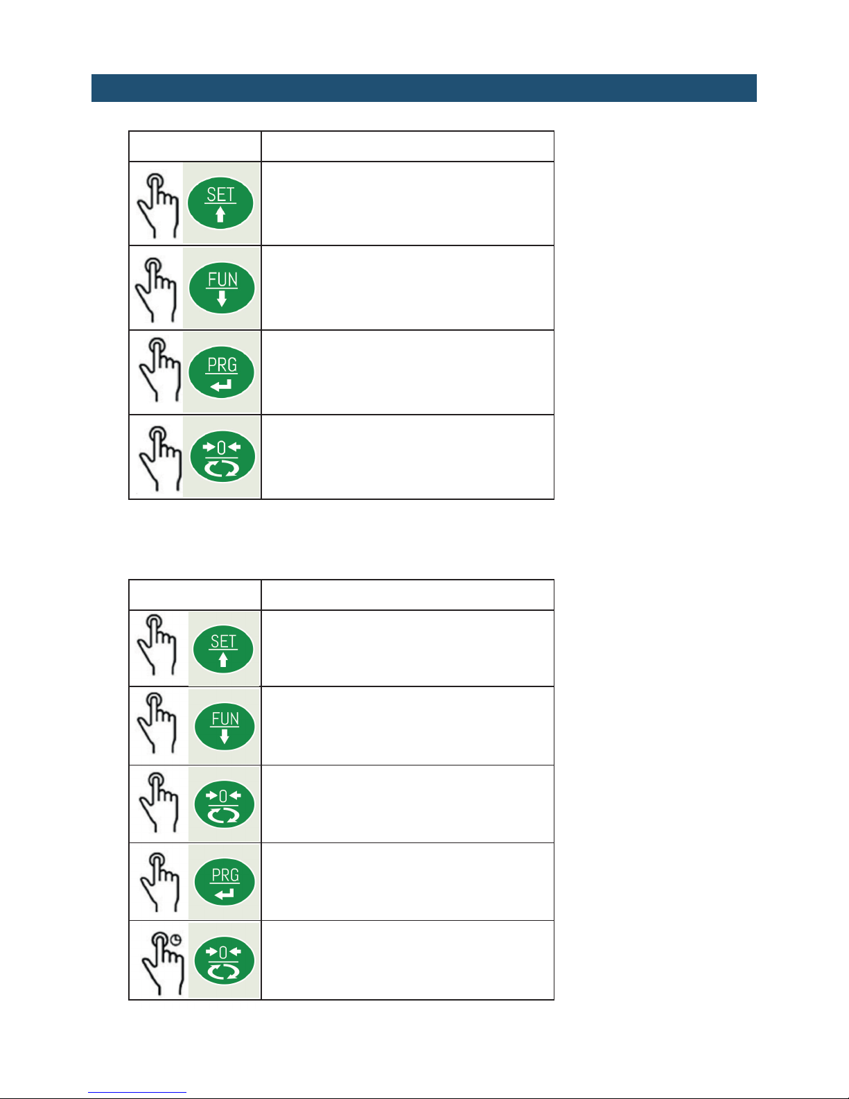
BROWSERING THE PROGRAMMING MENU
Operation Description
Go to the previous menu item.
Go to the next menu item.
Access the function for the displayed item.
Exit menu or return to the top level.
PROGRAMMABLE VALUE COMPOSITION
Operation Description
Increases the selected digit.
Decreases the selected digit.
Selects the next digit.
Ends composition and stores the value.
Resets all digits.
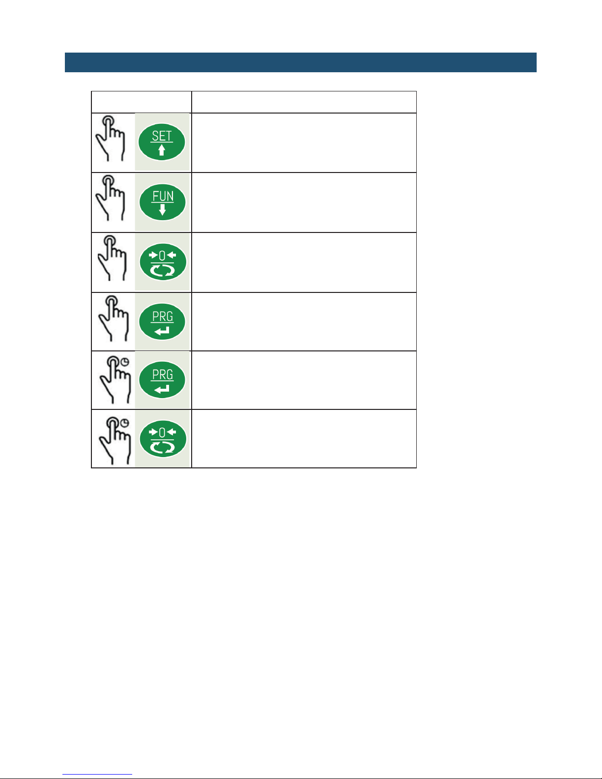
MAIN FUNCTIONS
Operaton Description
Enters the setpoint setting
Switches display (Gross/Net/Cells)
Sends string onto the serial item
Enters the Programming menu
Performs semi-automatic zeroing

PROGRAMMING MENU
To access the programming menu, press and hold the long PRG key in the weight display
screen.
ACCESS TO THE MENU WITH METRIC OPERATION (Jumper enabled)
The programming of the weighing parameters and the weight calibration settings are allowed
only to personnel authorized by current legislation, through password protected access or by
activating the calibration DIP switch (CAL). In the case of a calibration DIP switch set to ON,
the access password is not required (procedure described below).
This procedure requires the password table.
To access the menu, the operator identification code is required. The timed
message “ID” is displayed and then the code is entered, so enter the
identification code of the authorized access operator, corresponding with the
password table number and confirm with ENTER. If the value 0000 is confirmed,
access to the menu parameters will be limited (it will not be possible to access
the programming of the weighing parameters and the weight calibration
settings).
A randomly determined 3-digit number appears on the display. Find the
corresponding password (4-digit) on the table
Enter the password obtained from the table and confirm with the ENTER key. If
the value 0000 is confirmed, access to the menu parameters will be limited (it
will not be possible to access the programming of the weighing parameters and
the weight calibration settings).
Each access of authorized personnel is recorded in the searchable memory of
the last 5 accesses.
In case of non-metric use, the jumper must be set in CALIBRATION position; in
this way, the access to the menu is free (without password request).
ID: 001
Cod: 123
Pw: 1234

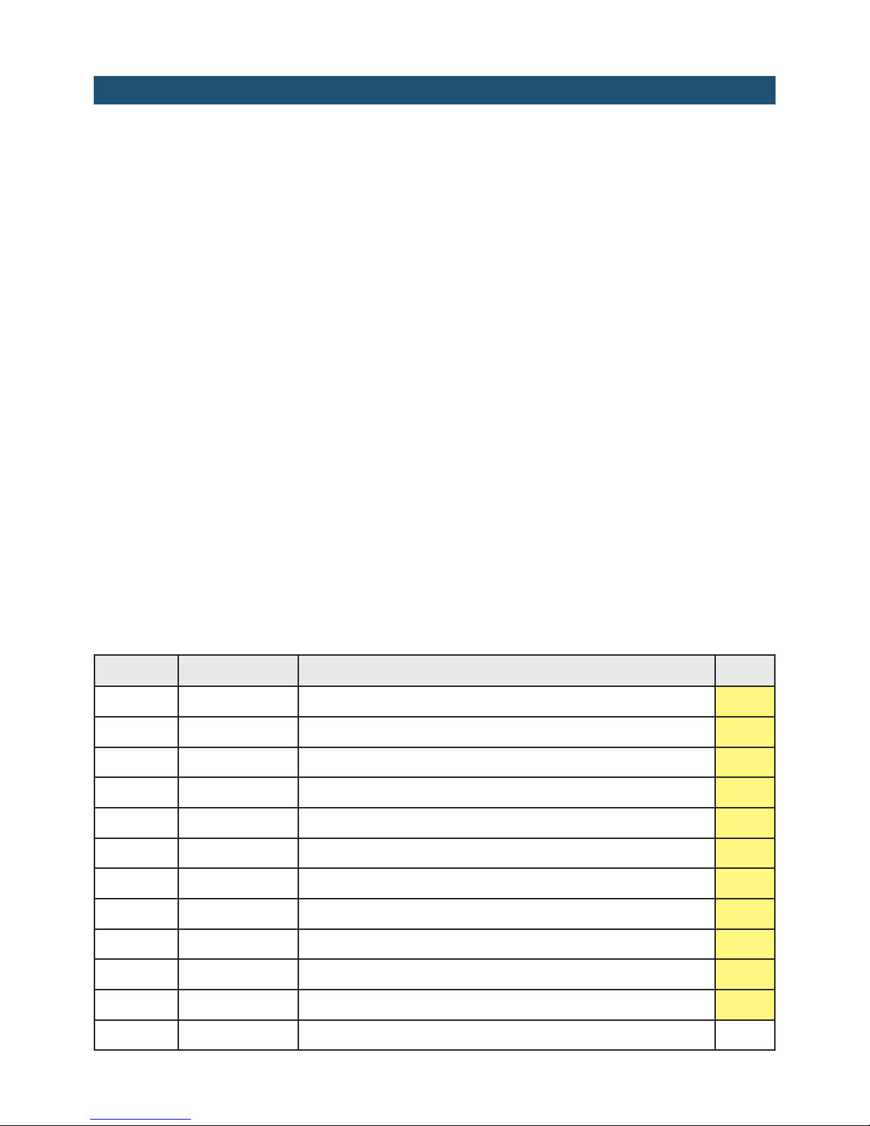
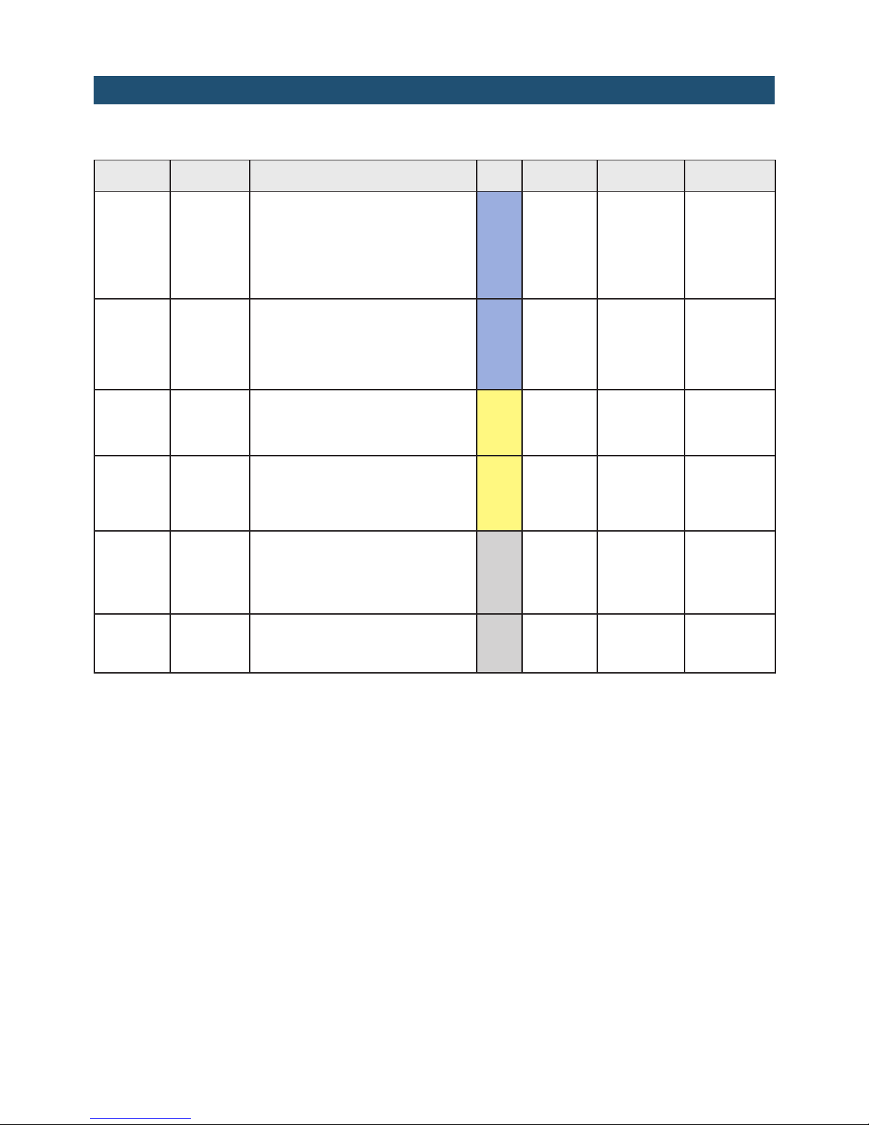
MENU NAME DESCRIPTION
INFO Information: Parameter menus that can be displayed for identification of the
device and its configuration.
TEST Test Menu of the instrument's hardware test operation procedures.
SETUP Setup Menu of the programmable parameters that determine the start-
up of the instrument.
Menu Message Name Description Type
INFO FIRMWARE Firmware code Indication of the installed Firmware code Screen
FULL SCALE Full scale of the device Indication of the set full scale value Screen
N.OF CELLS Number of cells enabled Indication of the number of enabled cells Screen
FIELDBUS Fieldbus present Indication of the type of fieldbus configured Screen
ADDRESS Fieldbus address Indication of the set fieldbus address. This menu
item is only displayed in the RS485 and PROFIBUS
configurations.
Screen
IP ADDRESS Fieldbus IP address Indication of the set fieldbus IP address. Item di-
splayed only in the PROFINET and ETHERNET/
IP configurations.
Screen
SUBNET Fieldbus Subnet Mask Indication of the set fieldbus subnet mask. Item
displayed only in the PROFINET and ETHERNET/
IP configurations.
Screen
ANALOG
OUT
Analog output configu-
ration
Indication of presence and type of analogue
output (Not present - Unipolar - Bipolar)
Screen
MEMORY Optional Memory Con-
figuration
Indication of presence and type of memory
(None - Alibi memory)
Screen
In the case of PROFINET field bus: the IP address and Subnet Mask parameters are programmable by PLC and are
updated in this menu only when the device is switched on; after a change in these parameters from the PLC, it is
necessary to switch the device off and on again to display the correct value. It is important to remember that even
if you set the IP address and subnet mask parameters in Temporary mode, these parameters are not automatically
updated in the device. Moreover, when the device is turned off and on again, these parameters will be all set to
0.0.0.0.

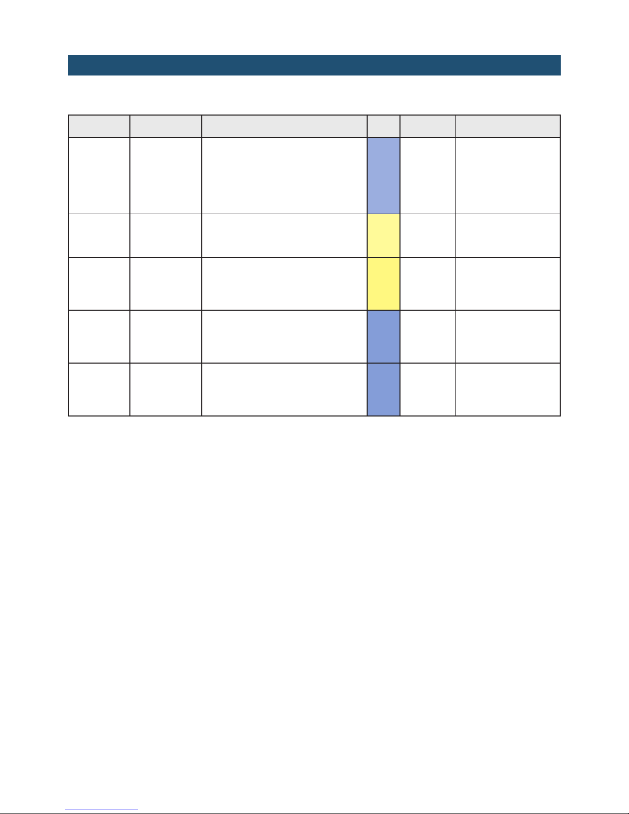
Menu Message Name Description Type
TEST
SIGNAL Cell signal Display of the mV/V signal input to the device Screen
HI-RES Resolution x10 Display of the weight with a resolution 10 times
greater than the one set
Screen
PWR
SUPPLY
Supply voltage Display of the supply voltage measured by the
device
Screen
MEMORY Memory test
(Only with configured
memory)
Automatic test of operation of the additional
memory
Test
IN / OUT I/O test I/O test with simultaneous display of inputs and
outputs
(See specific description)
Test
RS 232 RS232 test Sending and reception test
(See specific description)
Test
RS 485 RS485 test Sending and reception test Test
ANALOG
OUT
Analog output test Test procedure with manual activation of the ou-
tput value (See specific description)
Test
Menu Sub Menu Name
SETUP
CALIBRATION Calibration Settings (*)
ANALOG Analog output settings (Only with configured analogue output)
CONNECTIONS Serial and fieldbus port settings
IN OUT Logical Input and Output Settings
PARAMETERS Measurement metrological parameters settings (*)
FILTER Filter settings
FUNCTIONS Functional characteristics settings
CLOCK Date clock settings (***)
ACCESSES Display of the last 5 authorized personal accesses (**)
ALIBI MEM. Consultation of fiscal memory (**)
(*) These menu items are only displayed in the case of FREE operation or in case of authorized personnel access via
password (in case of METRIC operation).
(**) These menu items are only displayed in the case of METRIC operation.
At the exit of the setup menu, if changes have been made to the parameters, the message SAVING IN PROGRESS is
displayed
(***) This menu item is only displayed in case of hardware with a date clock.

CALIBRATION SETTINGS
Access to this menu is only permitted in the case of FREE operation or in case of authorized personnel
access via password (in case of METRIC operation).
CALIBRATION SUBMENU:
Menu Name Description Type Default Range Fieldbus
Addr.
UNITS
Unit of
measure
Selecting the measurement
unit used, the desired unit of
measurement can be set.
kg
RESOLUTION Division
value
Value of a single division. The
ratio between the maximum
system capacity and the division
value constitutes the system
resolution (number of divisions).
Sel. 1
0,0001 ÷ 50
In steps of
1,2,5
(*)
CAPACITY Load cell
capacity
Value of the nominal capacity of
each cell, in the selected unit of
measure. Following the change
in these values, the theoretical
calibration is performed.
Com. 0 0 ÷ 999999 1103 (MSB)
1104 (LSB)
SENSITIVITY
Sensitivity
of load
cells
Sensitivity of every single
cell. Following the change,
the theoretical calibration is
performed.
Com. 2
mV/V
0,1 ÷ 4
mV/V 1105
FULL-SCALE Full-scale
Maximum system capacity limit.
Following the change, the
analogue scale full scale value is
set.
Com. 0 0 ÷ Cells
capacity
1301 (MSB)
1302 (LSB)
DEAD
WEIGHT Fixed tare
Programming of the fixed tare
value (in kg). Following the
change, a theoretical zero
calibration is performed.
Com. 0 0 ÷
Capacity
1106 (MSB)
1107 (LSB)
CAL.TYP
Selection of the type of
calibration. Upon confirmation,
one of the following procedures is
started.
Sel. Dead Weight
o Table, EQ
BALANCING Balancing
It performs a compensation of the
load cells so that they all have the
same weight response
Spc
DEAD W.
Dead
Weight
calibrat.
Calibration of Zero and Weight
Sample and linearization with
sample weights (***)
Spc 501÷503
TABLE Table calibration (****) Spc 1151÷1172
G-CAL Severity Gravity acceleration at the
calibration site. (**) Com. 0 977000÷
984000
1108 (MSB)
1109 (LSB)
G-USE Use
gravity
Acceleration of gravity in the
place of use. (**) Com. 0 977000÷
984000
1110 (MSB)
1111 (LSB)

LOAD CELLS BALANCING
The procedure can be performed if at least 2 load cells are used, otherwise, the menu will not be
active.
AUTOMATIC PROCEDURE
To carry out the automatic balancing procedure, a weight must be provided to be moved over the various cells to
perform the calculation.
Once you have entered the menu and set the scale zero, you must set the value of the weight used for the procedure,
so that the automatic weighing calibration is also carried out at the end.
• At this point, the device will indicate to load the cell number 1.
• Load the sample weight and press the ENTER button
• Then proceed with the subsequent cells until the last one
If the loaded cell is not correct or if the procedure is not successful, the device will give an error; in
this case, correct the problem and try the procedure again.
BALANCING FACTOR
It is possible to manually modify the balancing factor, by accessing the appropriate menu and modifying the value
present in the selected cell.
The value can be set from 0.1000 to 9.9999 (the default value is 1.0000).
WEIGHT CALIBRATION
(*) The setting of the division values via fieldbus takes place differently from that made by the device. Refer to the
1101 and 1102 addresses of the MODBUS register table.
(**) These parameters only available in the case of METRIC operation.
(***) SAMPLE WEIGHT CALIBRATION AND LINEARIZATION
Once the DEAD W. function has been selected, it is possible to perform the zero calibration or the sample weight
procedure.
Zero calibration: (ZERO key pressed for a long time): Perform the operation with the empty scale but complete with
the tare weight stabilized. The displayed weight must be reset. This operation can be repeated several times. Exit the
CAL. function by pressing the PRG key for a long time.
Sample weight calibration: (short press SET key) Before carrying out the operation, load the sample weight on the
scale and wait for it to stabilize; the display shows the measured value to be calibrated, through the composition of
a programmable value. If the set value is higher than the resolution offered by the device, it is not accepted and the
display shows an error message for a few seconds. Confirm the weight value by pressing the PRG key for a long
time.
Exit the CAL. function by pressing the PRG key for a long time.
Linearization with sample weights: (long press SET key) Up to 5 linearization points on a positive scale are possible.
The progressive linearization points are displayed alternately with the current weight. Press the SET button to set the
value of the sample weight loaded and stabilized. Upon confirmation, proceed to the next step. If 0 is set, the value
is not stored. To end the procedure, press the PRG key for a long time. It is possible to store a number of points lower
than 5.
It is always possible to repeat the calibration operations.
(****) TABLE CALIBRATION
It allows you to manually program up to five calibration points, in addition to the zero value. The values correspond
to those determined by the linearization procedure with sample weights. In this way, it is possible to display the
values determined automatically with this procedure or modify and program them according to preset values.
Message Name Description Type
0 SIGNAL
Zero signal Signal value in mV/V corresponding to the scale zero. Com.
P1 VALUE Weight of point 1 Weight value corresponding to the 1st calibration point Com.
P1 S1GNAL Signal of point 1 Signal value corresponding to the 1st calibration point. Com.
P2 VALUE Weight of point 2 Weight value corresponding to the 2nd calibration point. Com.
P2 S1GNAL Signal of point 2 Signal value in mV/V corresponding to the 2nd calibration point. Com.
P3 VALUE Weight of point 3 Weight value corresponding to the 3rd calibration point. Com.
P3 S1GNAL Signal of point 3 Signal value in mV/V corresponding to the 3rd calibration point. Com.
P4 VALUE Weight of point 4 Weight value corresponding to the 4th calibration point. Com.
P4 S1GNAL Signal of point 4 Signal value in mV/V corresponding to the 4th calibration point. Com.
P5 VALUE Weight of point 5 Weight value corresponding to the 5th calibration point. Com.
P5 S1GNAL Signal of point 5 Signal value in mV/V corresponding to the 5th calibration point. Com.
GET 0 Zero capture Capturing the signal in mV/V corresponding to the scale zero. Spc
ANALOG OUTPUT SETTINGS
ANALOG SUBMENU:
Message Name Description Type Default Range Ind.Fieldbus
RANGE
Analog
output
range
Selection of the analogue output
type Sel. 0÷10V
0-10V [0]
0-5V [1]
4-20mA [2]
0-20mA [3]
1506
MODE
Analog
output
mode
Selection of the value sent by
analog output. Sel. NET
NET [0]
GROSS [1]
PEAK [2]
1505
ANA 0 Fixed tare Analog output offset Com. 0 1501 (MSB)
1502 (LSB)
ANA FS Full-scale
It is the weight corresponding to
the full scale of the analog output,
which may be different from the
weighing system's capacity.
Com. Maximum
capacity 0÷Capacity 1503 (MSB)
1504 (LSB)
0 ADJ. Adjusting
zero
User procedure for zero adjustment
(*) Spc 0
FS.ADJ. Full scale
adjustment
User procedure for full scale
adjustment (*) Spc 0
(*) The analog output is calibrated at the factory for each selectable range. This further procedure is
available to the user for adjustment, for each selectable range. In case of complete reset of the setup
memory, the factory calibration is re-established.

SERIAL PORTS – RS232 SETTINGS
CONNECTIONS SUBMENU:
Message Name Description Type Default Range
C1 MODE
RS232 output
mode Selection of the value sent by
RS232 output.
Sel. NET NET
GROSS
PEAK
C1 PROT. RS232 com-
munication
protocol
Selection of the communication
type for the RS232 ports
Sel. None None
Continuous tx
On demand
Automatic
Slave
Printer
C1 BAUD RS232 Bau-
drate
Selection of the Baudrate for the
RS232 port
Sel. 9600 1200 ÷ 115200
C1 FORM RS232 Frame Frame type.
In the case of a SLAVE protocol, it
is not possible to select 7-bit data
format (E-7-1 and O-7-1):
Sel. N-8-1 N-8-1, N-8-2, E-7-2
E-8-1, O-7-2, O-8-1
SERIAL PORTS – RS485 SETTINGS
CONNECTIONS SUBMENU:
Message Name Description Type Default Range
C2 MODE
RS485 output
mode Selection of the value sent by
RS485 output.
Sel. NET
As for C1 Mod.
C2 PROT. RS485 com-
munication
protocol
Selection of the communication
type for the RS485 ports
Sel. None None
Continuous tx
On demand
Automatica
Slave
ModBus
C2 BAUD RS485 Bau-
drate
Selection of the Baudrate for the
RS485 port
Sel. 9600 1200 ÷ 115200
C2 FORM RS485 Frame Frame type.
In the case of a SLAVE or MODBUS
protocol, it is not possible to select
7-bit data format (E-7-1 and O-7-1):
Sel. N-8-1 N-8-1, N-8-2, E-7-2
E-8-1, O-7-2, O-8-1
C2 ADDR. RS485 ad-
dress
Communication address of the
device
Com. 1 1 ÷ 32

SERIAL PORTS SETTINGS - ETHERCAT CONFIGURATION
CONNECTIONS SUBMENU:
Message Name Description Type Default Range
EN.FBUS.
Abilitazione-
Fieldbus
Enabling EtherCAT Fieldbus; if
OFF, no error message regarding
the EtherCAT communication is
displayed
Sel. OFF OFF
ON
INP.REG. Dimension
Input Area
Dimension of the input area
for EtherCAT fieldbus (values
expressed in bytes).
Sel. 128 32, 64, 96, 128
OUT.REG. Dimension
Output Area
Dimension of the output area
for EtherCAT fieldbus (values
expressed in bytes).
Sel. 128 132, 64, 96, 128
In case of ETHERCAT fieldbus: the devices must be connected with a ring type (as specified by
EtherCAT), so refer to the installation manual for the use of INPUT and OUTPUT ports
4 different XML setting files are provided:
“Hilscher NIC 50-RE ECS V2.2 32 Byte.xml” (input area: 32-byte, output area: 32 byte).
“Hilscher NIC 50-RE ECS V2.2 64 Byte.xml” (input area: 64-byte, output area: 64 byte).
“Hilscher NIC 50-RE ECS V2.2 96 Byte.xml” (input area: 96-byte, output area: 96 byte).
“Hilscher NIC 50-RE ECS V2.2 128 Byte.xml” (input area: 128-byte, output area: 128 byte).
The file that corresponds to the size of the input and output areas selected in the device must be imported into the PLC
(for example, if the device is set to IMP.REG.=128 and OUT.REG.=128.=128, the file “Hilscher NIC 50-RE ECS V2.2
128 Byte.xml” must be imported into the PLC). Multiple files with different sizes can be imported, but, in this case, it
will not be possible to perform the automatic search and setup of devices on the network

SERIAL PORTS SETTINGS - PROFIBUS CONFIGURATION
CONNECTION SUBMENU
Message Name Description Type Default Range
EN.FBUS.
Enabling
Fieldbus
Enabling Profibus fieldbus;if OFF,
no error message regarding
the Profibus communication is
displayed
Sel.
OFF OFF
ON
ADDR.PR. Profibus Ad-
dress
Communication address of Profibus
protocol
Sel. 1
1 ÷ 126
INP.REG. Dimension
Input area
Dimension of the input area for
Profibus fieldbus (values expressed
in bytes)
Sel.
128 32, 64, 96, 128
OUT.REG. Dimension
Output area
Dimension of the output area for
Profibus fieldbus (values expressed
in bytes). 128 32, 64, 96, 128
SERIAL PORTS SETTINGS - PROFINET CONFIGURATION
CONNECTION SUBMENU
Message Name Description Type Default Range
EN.FBUS.
Enabling
Fieldbus
Enabling Profinet fieldbus;if OFF,
no error message regarding
the Profinet communication is
displayed
Sel.
OFF OFF
ON
INP.REG. Dimension
Input area
Dimension of the input area for
Profinet field (values expressed in
bytes).
Sel. 128
32, 64, 96, 128
OUT.REG. Dimension
Output area
Dimension of the input area for
Profinet field (values expressed in
bytes).
Sel.
128 32, 64, 96, 128
The XML “GSDML-V2.3-HILSCHER-NIC 50-RE PNS 32-20160122.xml” configuration file is
provided. The size of the input and output areas set in the PLC (possible selections: 32, 64,
96 or 128 bytes) must correspond to the size of the input and output areas selected in the
instrument (“INP.ADJ.” And “OUT.ADJ.” Parameters).
The instruments are supplied with the parameter “Profinet Name” not setup and with an IP
address of 0.0.0.0.
SERIAL PORTS SETTINGS - ETHERNET/IP CONFIGURATION
CONNECTION SUBMENU
Message Name Description Type Default Range
EN.FBUS.
Enabling
Fieldbus
Enabling Profibus fieldbus; if OFF,
no error message regarding the
Ethernet/IP communication is
displayed
Sel.
OFF OFF
ON
IP IP Address Protocol IP address Ethernet/IP Com.
0.0.0.0
0.0.0.0
÷
255.255.255.255
SUBNET. Subnet Mask Subnet Mask Ethernet/IP protocol Com.
0.0.0.0
0.0.0.0
÷
255.255.255.255
INP.REG. Dimension
Input area
Dimension of the input area
for Ethernet/IP fieldbus (values
expressed in bytes)
Sel.
128 32, 64, 96, 128
OUT.REG. Dimension
Output area
Dimension of the input area
for Ethernet/IP fieldbus (values
expressed in bytes).
Sel.
128 32, 64, 96, 128
The EDS configuration file “HILSCHER NIC 50-RE EIS V1.1.EDS” is provided. The size of the input and output areas
set in the PLC (default input area of 128 bytes, default output area of 128 bytes) must match the size of the input and
output areas selected in the instrument (“INP.ADJ.” Parameters and “OUT.ADJ.”).
This manual suits for next models
1
Table of contents
Other Pavone Sistemi Accessories manuals

Popular Accessories manuals by other brands


Mesalabs
Mesalabs Smart-Well 1710 Operation manual

Waterpik
Waterpik WF-20 Series user manual

Philips
Philips HF3505 user manual

Heathkit
Heathkit Heathkit HP-1144 Guide manual

Barbarian Basketball Systems
Barbarian Basketball Systems Titanium Series Assembly instructions and owner's manual

Omni Ultraviolet
Omni Ultraviolet UV WAND SANITIZER manual