Pavone Sistemi DAT 500 User manual

Pavone Sistemi
pesatura elettronica industriale
TECHNICAL MANUAL
DAT 500 Weight Indicator/Transmitter with serial and ANALOG output
Software version PW13012

Page II

Page 1
Rel ID 152100 sw1.7
TABLE OF CONTENTS
PRECAUTIONS.............................................................................................. Page 2
INTRODUCTION ........................................................................................... Page 3
TECHNICAL FEATURES................................................................................... Page 4
INSTALLATION .............................................................................................. Page 5
FRONT PANEL OF THE INSTRUMENT .............................................................. Page 8
USING THE KEYBOARD ................................................................................. Page 9
INFO DISPLAY ............................................................................................... Page 11
VIEWING, ZEROING THE WEIGHT AND SELF-CALIBRATION............................. Page 12
SETTING....................................................................................................... Page 16
CHART OF THE MENU................................................................................... Page 18
SETTING PARAMETERS................................................................................... Page 20
CALIBRATION................................................................................................ Page 23
WEIGHTING PARAMETERS............................................................................. Page 25
INPUT/OUTPUT PARAMETERS......................................................................... Page 27
SERIAL OUTPUT PARAMETERS......................................................................... Page 30
ANALOG OUTPUT PARAMETERS..................................................................... Page 33
SERIAL COMMUNICATION PROTOCOLS ........................................................ Page 35
UPLOAD AND DOWNLOAD FUNCTION......................................................... Pag. 48
TROUBLESHOOTING ..................................................................................... Pag. 53

Page 2
PRECAUTIONS
READ this manual BEFORE operating or servicing the instrument.
FOLLOW these instructions carefully.
SAVE this manual for future use.
CAUTION
The installation and maintenance of this instrument must be allowed
to qualified personnel only.
Be careful when you perform inspections, testing and adjustment
with the instrument on.
Perform the electrical connections in the absence of the power supply
Failure to observe these precautions may be dangerous.
DO NOT allow untrained personnel to work, clean, inspect, repair
or tamper with this instrument.
Page 3
PAVONE SISTEMI
INTRODUCTION
The DAT 500 is a transmitter of weight to be combined with the load cells to detect the weight in every
situation.
The module is easy to install and can be mounted on a front panel.
The display allows easy reading of the weight, the status of the instrument, the setting parameters and
errors.
The 4 keys located below the display allow the operator to perform the functions of ZERO, TARE,
GROSS/NET switching, setting of the setpoints weight, setting and tare both theoretical than real.
The DAT 500 uses the serial port RS232 with ASCII and Modbus RTU protocols for connecting to a
PC, PLC and remote units.
They are always available 2 programmable weight setpoints and the control of the maximum weight
value reached (peak).
The RS422/RS485 serial output allows you to connect up to 32 addressable devices.
The availability of the most common fieldbuses, as an alternative to the RS422/RS485 port, also allows
the transmitter to interface with any supervision device currently offered by the market.
Available versions:
DAT 500: weight transmitter with serial output RS232, RS485 and Peak function. Supported protocols
are Modbus RTU, continuous, slave and the ones upon request. Two programmable setpoints, 2 inputs
and Peak function.
• DAT 500/A: version with the analog output.
• DAT 500/PROFIBUS: weight transmitter with serial output RS232 and PROFIBUS DP.
• DAT 500/DEVICENET: weight transmitter with serial output RS232 and DEVICENET.
IDENTIFICATION PLATE OF THE INSTRUMENT
It’s important to communicate this data in the event of a request for information or information concer-
ning the instrument together with the program number and version that are shown on the cover of the
manual and are displayed when the instrument is switched on.
WARNINGS
The following procedures must be performed by qualified personnel.
All connections must be performed when the instrument is turned off.

Page 4
TECHNICAL FEATURES
Power supply 24 Vdc ± 15 %
Max. absorption 5W
Insulation Class II
Installation category Cat. II
Operating temperature -10°C ÷ +40°C (max. humidity 85% non-condensing)
Storage temperature -20°C ÷ +50°C
Weight display Numerical with 6 red led digits and 7 segments (h 14
mm)
Led 4 LEDs of 3 mm
Keyboard 4 mechanical keys
Overall dimensions 48 x 96 x 148 mm (l x h x w)
Installation Panel mount; cutout 45 x 92 mm
Case material self-extinguishing Noryl (UL 94 V1)
Connections Screw terminal boards, pitch 5.08 mm
Load cells power supply 5 Vdc/120 mA (max 8 cells of 350 Ω in parallel),
short-circuit protected
Input sensitivity 0.02 µV min.
Linearity 0.01% of the full scale
Temperature drift 0.001% of the full scale /°C
Internal resolution 24 bits
Resolution of the weight displayed Up to 60,000 divisions on the net capacity
Measurement range –0.5 mV/V to +3.5 mV/V
Frequency of weight capture 5 ÷ 50 Hz
Digital filter To be selected from 0.2 Hz to 25 Hz
Number of weight decimals 0 ÷ 3 decimal places
Zero calibration and full scale Automatic (theoretical) or executable from the
keyboard.
Logic outputs 2 opto-isolated (dry contact), max 24Vdc / 60 mA
each
Logic inputs 2 opto-isolated at 24 Vdc PNP (external power supply)
Serial port (# 2) RS232C and RS485
Maximum cable length 15m (RS232) and 1000m (RS422 and RS485)
Serial protocols ASCII, Modbus RTU
Baud rate 2400, 9600, 19200, 38400, 115200 to be selected
Program code memory 64 Kbytes FLASH on-board reprogrammable from
RS232
Data memory 2 Kbytes
Analog output (optional) Voltage or current
Resolution 16 bits
Calibration Digital from the keyboard
Impedance Voltage: min. 10 KΩ Current: max 300 Ω
Linearity 0.03 % of the full scale
Temperature drift 0.001% of the full scale / °C
Compliance with the standards EN61000-6-2, EN61000-6-3 for EMC
EN61010-1 for Electrical Safety
UL: FILE NO E474362
Page 5
48
96 139
130
148
44
90
1
2
3
13
14
15
16
17
18
19
20
21
22
23
24
4
5
6
7
8
9
10
11
12
+24 Vdc
0 Vdc
INSTALLATION
GENERAL DATA
The DAT 500 is composed of a motherboard, on which you can add the options available; the mother-
board is housed in a plastic enclosure for panel mounting.
The DAT 500 should not be immersed in water, subjected to jets of water and cleaned or
washed with solvents.
Do not expose to heat or direct sunlight.
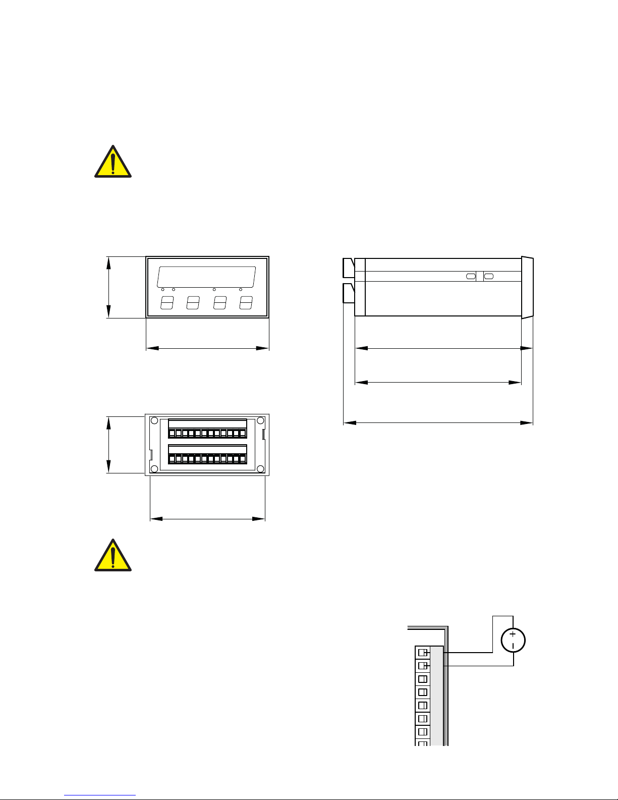
OVERALL DIMENSIONS
ELECTRIC INSTALLATION
The transmitter DAT 500 uses screw terminal boards, pitch 5.08 mm, for the electrical con-
nection. The load cell cable must be shielded and channeled away from tension cables to
prevent electromagnetic interference.
INSTRUMENT POWER SUPPLY
The instrument is powered through the terminals 1 and 2. The power
cord must be channeled separately from other cables.
The supply voltage is electrically isolated.
Power supply voltage: 24 Vdc/ ± 15% max. 5W
Page 6
1
2
3
13
14
15
16
17
18
19
20
21
22
23
24
4
5
6
7
8
9
10
11
12
LOAD CELLS
- Exc
+ Exc
+ Sense
- Sense
- Sig
+ Sig
2+SGN
3-EXC
6+EXC
1-SGN
5+SNS
4-SNS
7SHD
+EXC
-EXC
+SGN
-SGN
SHD
1
2
3
4
5
+EXC
-EXC
+SGN
-SGN
SHD
1
2
3
4
5
+EXC
-EXC
+SGN
-SGN
SHD
1
2
3
4
5
+EXC
-EXC
+SGN
-SGN
SHD
1
2
3
4
5
J-BOX CGS4DAT 500
SENSE-
SENSE+
I OUT+
V OUT+
SIGN-
SIGN+
C OUT
S GND
C OUT
OUT2
C IN
EXC-
EXC+
OUT1
IN2
RX-
RX+
T X -
TX+
IN1
TXD
RXD
24
12
11
10
23
24
19
22
21
20
14
15
16
17
18
13
9
8
3
4
5
1
2
+
-
6
7
+24V
+EXC
-EXC
+SGN
-SGN
SHD
+EXC
-EXC
+SGN
-SGN
SHD
+EXC
-EXC
+SGN
-SGN
SHD
+EXC
-EXC
+SGN
-SGN
SHD
1
2
3
13
14
15
16
17
18
19
20
21
22
23
24
4
5
6
7
8
9
10
11
12
INPUTS
24 VDC
INPUT 1
INPUT 2
+
-
COM. INPUT
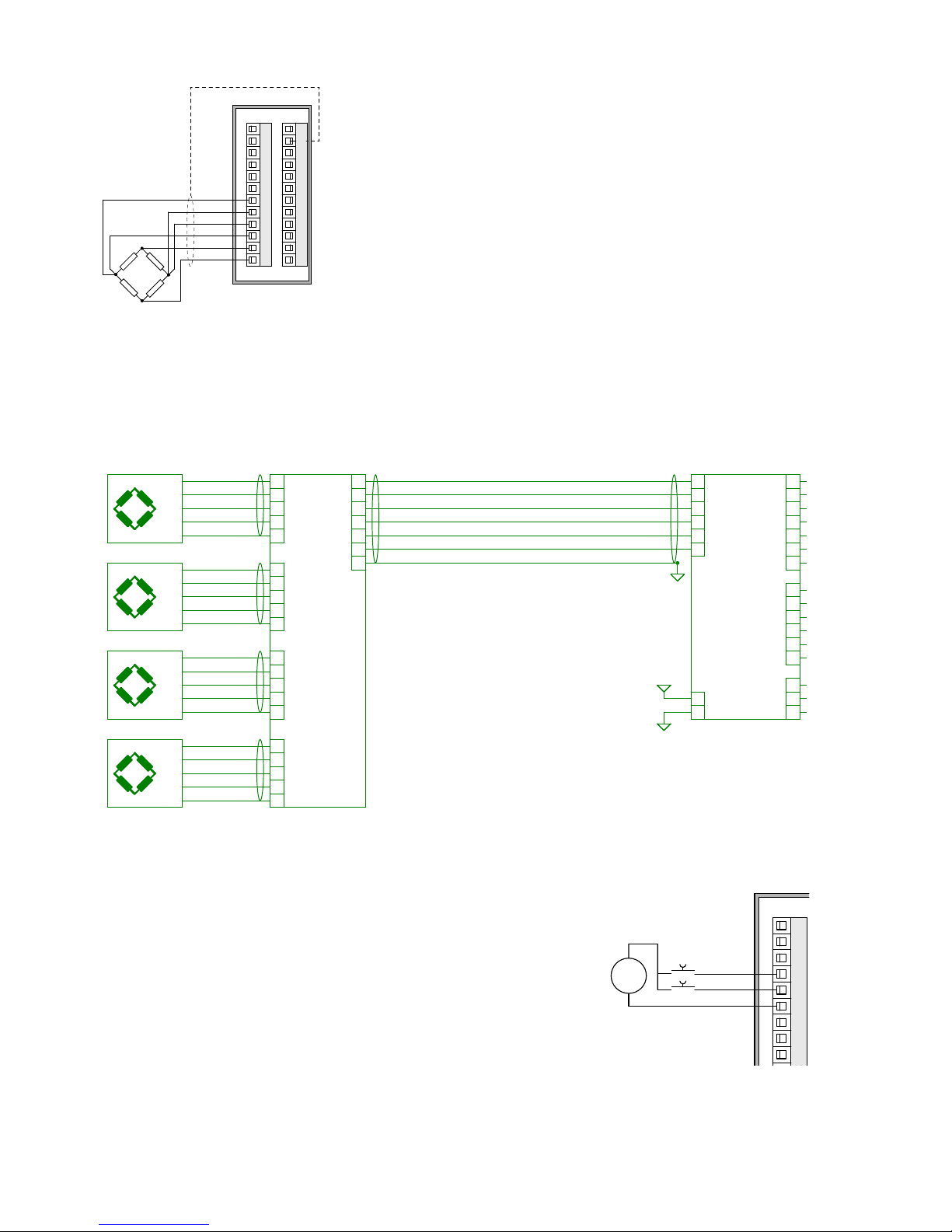
CONNECTIONS OF THE LOAD CELL/S
The cell/s cable must not be channeled with other cables, but must
follow its own path.
The instrument can be connected up to a maximum of 8 load cells
of 350 ohm in parallel. The supply voltage of the cells is 5 Vdc and
is protected by temporary short circuit.
The measuring range of the instrument involves the use of load cells
with a sensitivity of up to 3.5 mV / V.
The cable of the load cells must be connected to terminals 19-24.
In the case of 4-wire load cell cable, jumper the terminals 19 to 22
and 20 to 21.
Connect the cell cable shield to the terminal 2.
In the case of the usage of two or more load cells, use special junction
boxes (CEM4/C or CSG4/C). Below please find their connection.
LOGIC INPUTS
The two logic inputs are opto-isolated.
The cable connecting the logic input should not be channeled with
the power cables.
The function of the two inputs is as follows:
INPUT1 Resetting the displayed value (gross, net or peak)
INPUT 2 PRINT
The activation of the two functions is accomplished by bringing the
external power supply 24 Vdc to the corresponding terminals as
shown in the figure.

Page 7
1
2
3
13
14
15
16
17
18
19
20
21
22
23
24
4
5
6
7
8
9
10
11
12
OUTPUTS
24 Vdc
100 mA Max
OUTPUT 2
OUTPUT 1
COM. OUTPUT
1
2
3
13
14
15
16
17
18
19
20
21
22
23
24
4
5
6
7
8
9
10
11
12
TXD
RXD
S.GND
SHIELD
RS232
(20m max)
1
2
3
13
14
15
16
17
18
19
20
21
22
23
24
4
5
6
7
8
9
10
11
12
S.GND
TXD+
TXD-
RXD+
RXD-
RS422/485
N°32 units max
(1000m max)
LOGIC OUTPUTS
The two opto-isolated relay outputs are the normally open contact.
The capacity of each contact is 24 Vdc, 100 mA max.
The cable connecting the outputs should not be channeled with the
power cables. The connection should be as short as possible.
SERIAL COMMUNICATION
RS232:
The RS232 serial port is always present and handles various pro-
tocols.
To achieve the serial connection, use a shielded cable, making sure
to connect the shield to one of the two ends: to pin 8 if connected
on the side of the instrument, to the ground if it is connected on the
other side.
The cable must not be channeled with power cables; the maximum
length is 15 meters (EIA RS-232-C), beyond which you should take
the optional RS485 interface.
ANALOG OUTPUT (OPTIONAL)
The transmitter provides an analog output in current and voltage.
Analog voltage output: range from -10 to 10 V or -5 to 5 V,
10 Kohm minimum load.
Analog current output: range from 0 to 20 mA or 4 to 20 mA. The
maximum load is 300 Ω.
To achieve the serial connection, use a suitable shielded cable,
making sure to connect the shield to one of the two ends: to pin
2 if connected on the side of the instrument, to the ground if it is
connected on the opposite side.
Attention: do not connect the analog output to devices that are
switched on.
RS485:
The serial port RS485 (2-wire) is present in the model DAT 500/
RS485.
To achieve the serial connection, use a suitable shielded cable,
making sure to connect the shield to one of the two ends: to pin
8 if connected on the side of the instrument, to the ground if it is
connected on the opposite side.
The cable should not be channeled with the power cables.
1
2
3
13
14
15
16
17
18
19
20
21
22
23
24
4
5
6
7
8
9
10
11
12
VOLTAGE (10 kΩ min)
ANALOG COM.
CURRENT (300 Ω max)
SHIELD

Page 8
SET FUN 0 PRG
1 2 NET
8.8.8.8.8.8.
PRECISE
DAT 400
FRONT PANEL OF THE INSTRUMENT
The DAT 500 has a bright 6-digit display, 4 status LEDs and four keys.
In this operating mode the display shows the weight and the LEDs indicate the status of weight and the
setpoints.
The set-up parameters are easily accessed and modified through the use of the three front buttons used
to select, edit, confirm and save the new settings.
DISPLAY
On the 6-digit display, it’s usually shown the scale weight. According to the various programming
procedures, the display is used for programming of the parameters to be stored in the memory, or the
messages that indicate the type of operation being carried out and help therefore the Operator in the
management and programming of the instrument.
LED INDICATORS
Below the display there are 4 LED indicators:
1 State of the logic output 1 (ON = closed contact OFF = open contact)
2 State of the logic output 2 (ON = closed contact OFF = open contact)
NET The displayed value is the net weight
0 IT indicates the condition of stable weight.
Page 9
USING THE KEYBOARD
The instrument is programmed and controlled through the keyboard which has 4 keys, with the following
functions: The selection of one of the key functions is established automatically by the instrument accor-
ding to the operation in progress. In general, the management of the programming menus is done by
using the
SET
and
FUN
keys to scroll through the items; the
PRG
key is used to enter its sub-menu or
programmable parameter, while the
0
button allows you exiting the menu or returning to the top level.
KEY FUNCTIONS DURING THE WEIGHT DISPLAY
SET Access to the menu for the programming of the setpoints
FUN Select the display view (gross weight, net weight).
(Long press) Selection of the weight/peak display
0Resetting the displayed value (gross weight, net weight or peak).
(Press and hold for 5 sec.) Calibration of zero, to be executed only if its function
is enabled in the PARAM menu (see item “0 ALL”).
PRG Sending the weight string on the serial line.
(Long press) Access to the quick set-up menu.
PRG
+
SET (Press for 3 sec) Access to the setup menu.
PRG
+
0(Press for3 sec) It accesses the keypad lock/unlock menu and auto-off function of
the display (see page 17).
KEY FUNCTION DURING THE MAIN MENU DISPLAY
SET It selects the next parameter.
FUN It selects the previous parameter.
0It exits the programming menu or returns to the upper level.
PRG It accesses the corresponding sub-menu or programming or confirms the selected
parameter.
Page 10
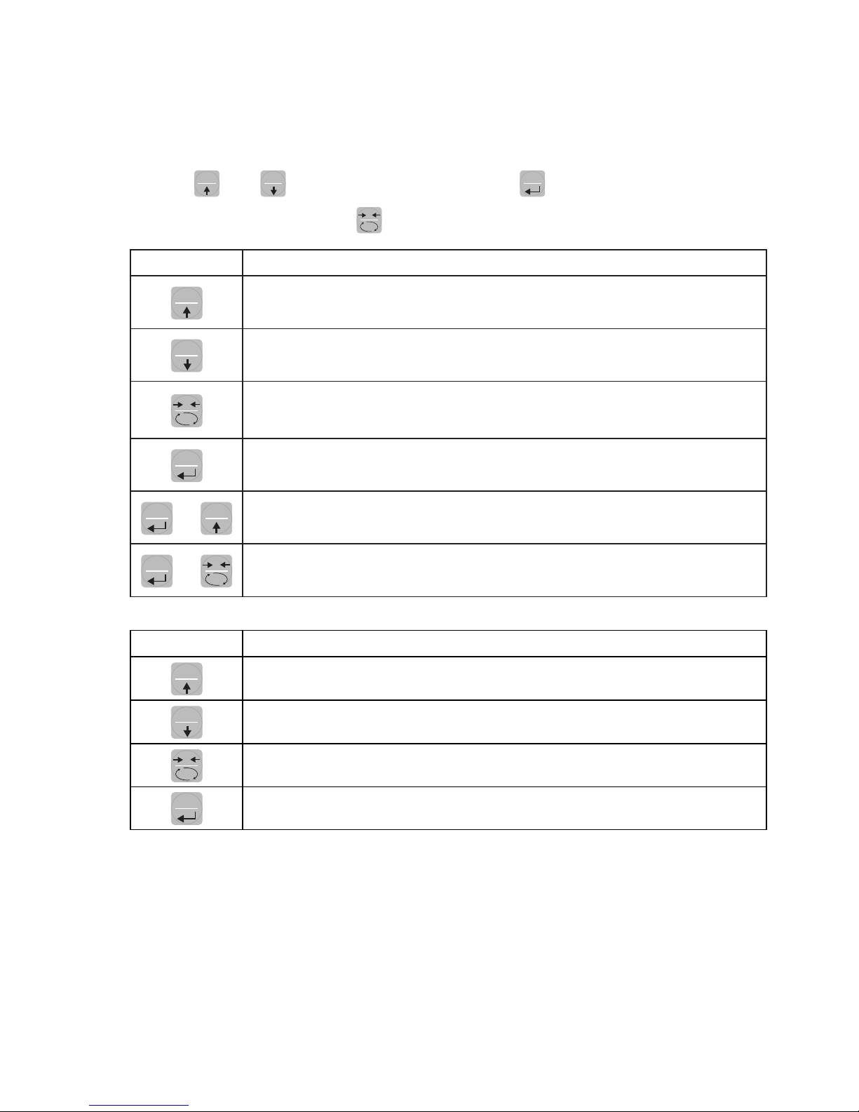
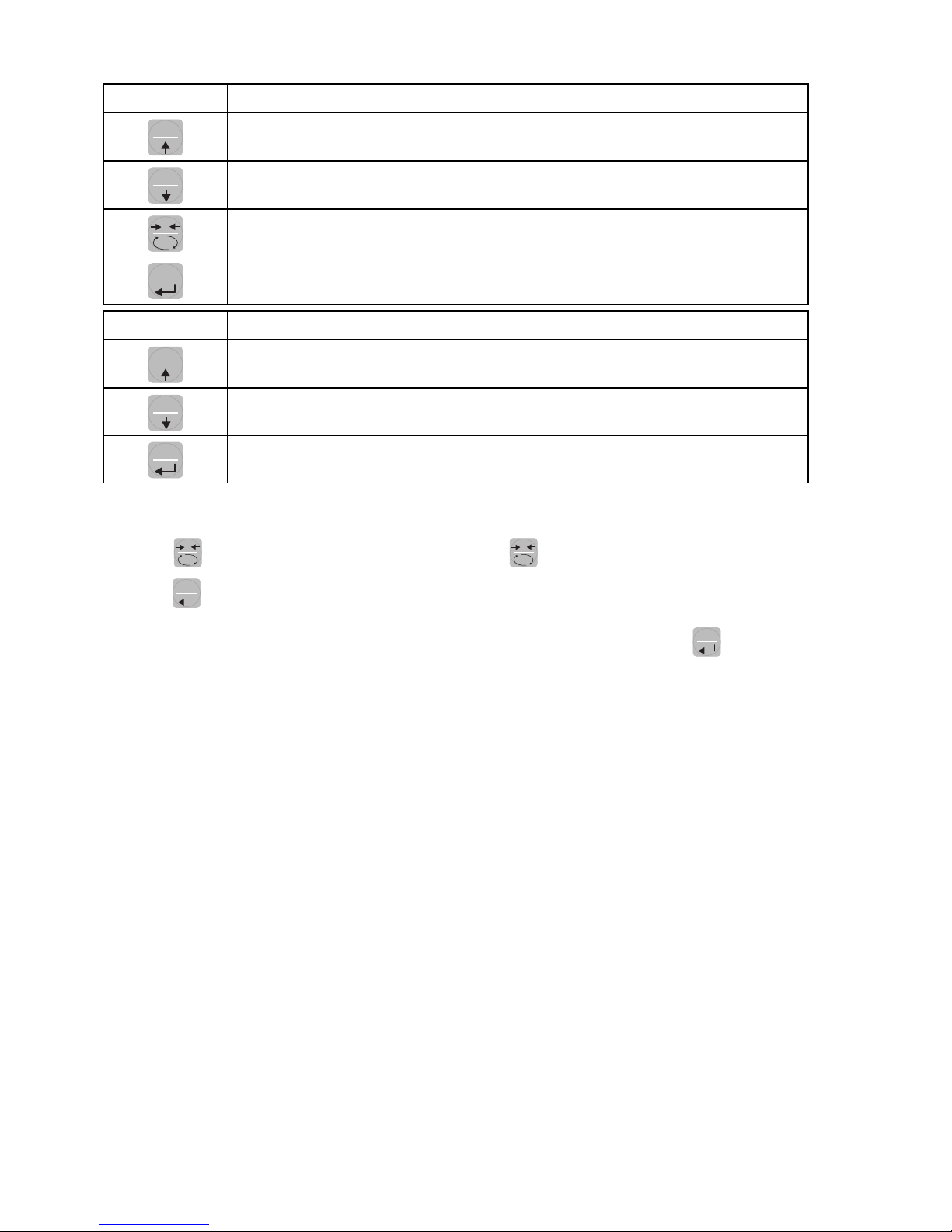
KEY FUNCTION WHEN SETTING THE NUMERICAL VALUES
SET It increases the value of the flashing digit.
FUN It decreases the value of the flashing digit.
0It goes to the next digit.
PRG It confirms the displayed value.
KEY FUNCTION WHEN SETTING THE NUMERICAL VALUES
SET It selects the next value.
FUN It selects the previous value.
PRG It confirms and store the displayed value.
EXIT FROM THE SETTING MENU
Press the
0
key to return to the main menu. Press the
0
. key again. It’s displayed “StORE?”.
Press the
PRG
key to return to the main menu.
To exit without saving any changes, switch off the instrument instead of pressing the
PRG
key.

Page 11
INFO DISPLAY
When the instrument is switched ON, you can test the display, then in sequence you can display the
identification code of the software and its version. Communication codes in the event of a request for
assistance.
ERRORS NOTIFICATION
In the operation mode, the display can report the following error codes.
the weight applied to the load cell exceeds by more than 9 divisions the maximum capacity
of the weighing system.
O-L Signal of the load cells absent or outside of the measurement range mV/V.
NO CON Fieldbus network disconnected.
E-PROF PROFIBUS interface absent or not operating.
E-dNEt DEVICENET interface absent or not operating.
Dash that runs along the perimeter of the display: BLIND function enabled.
ERR-CK Wrong checksum from Fieldbus

Page 12
VIEWING, ZEROING THE WEIGHT AND SELF-CALIBRATION
After being calibrated, at the subsequent switches on, the display shows the current weight.
VIEWING THE NET WEIGHT/GROSS WEIGHT
Press the
0
key to toggle between the net weight and the gross weight and vice versa. The value
displayed is signaled by the LED NET (lit: net weight). If you have not entered the tare, the net weight
is equal to the gross weight.
In case of negative weight, it is displayed the minus sign before the most significant digit.
ZEROING, WEIGHT AND SELF-CALIBRATION
These two functions are performed by pressing
0
.
When the instrument is in the operation mode “Net” (“NET” LED on), the
0
key performs the self-
calibration.
When the instrument is in operation mode “Gross” (“NET” LED off), the
0
key clears the gross weight.
SELF-CALIBRATION
The execution of self-calibration is possible under the following conditions:
• Instrument under conditions of “Net” (NET” LED on).
• Positive gross weight.
• Gross weight not greater than the maximum capacity.
• Stable weight.
• Unstable weight. In this condition, we must distinguish two cases:
1. The weight stability control is enabled (the parameter “MOTION” (*) must be other than zero): the
command executed while the weight is unstable only has an effect if the weight stabilizes within 3
seconds from the moment the command was given.
2. The weight stability control is disabled (the parameter “MOTION” (*) is equal to zero): the executed
command takes effect immediately, even with unstable weight.
(*) The operating modes of the parameter “MOTION” are described at page 23
The self-calibration is retained in memory even after the power is turned off.
ZEROING
The reset command of the gross weight is used to correct for small zero shifts of the weighing system
during normal operation.
Normally these zero shifts are due to thermal drifts or to residues of material that accumulate on the
weighing system over the time.
To run the command, it is necessary that the instrument is under conditions of “Gross” (“NET” LED off)
and that the deviation of the weight with respect to the zero of the scale (the one performed with the
calibration of zero) does not exceed (in positive or negative) the number of divisions set in parameter
“0 BAND” (inside the PARAM menu; see page 24).

Page 13
The reset command of the gross weight does not run if there is even one of the following conditions:
• Unstable weight (with control of the stability of the weight enabled). In this case, the reset command
takes effect only if the weight stabilizes within 3 seconds or if the control of the weight stability is
disabled (parameter “MOTION “ equal to zero).
• Gross Weight greater (in positive or negative) than the number of divisions set in parameter “0
BAND” , when the setpoint of auto-calibration is not programmed.
The zero obtained with the resetting of the gross weight is retained in memory even after the power is
turned off.
The reset operation of the gross weight can be repeated several times, but the number of reset divisions
zero is added from time to time, so when the total exceeds the limit value set in parameter “0 BAND”,
the zero cannot be executed. In this case, it is necessary to calibrate the Zero.
Any auto-zero parameter setting when switching on (AUTO 0) reduces (or cancels, in the case of “AUTO
0”> “0 BAND”) the range of action of the reset command.
PEAK FUNCTION
The instrument continuously memorizes the peak value of the gross weight. The peak value is detected
at the same frequency of acquisition of the weight (see table on filters). In addition to visualization, the
peak value can be used in the following functions:
FUNCTION DESCRIPTION
LOGIC OUTPUT The setpoints can be set to have the peak value as a reference. (See the
procedure for setting the logic outputs operations).
SERIAL PORT Acquisition of the peak value (peak hold) through the CONTIN, AUTO, DE-
MAND, and MODBUS SLAVE protocols.
ANALOG OUTPUT The analog output value can assume the value of the peak (peak old). (See
the procedure for setting the analog output).
Press the
FUN
key and hold it for 3 seconds until the left of the display shows the letter “P”.

Page 14
sEt 1 123456
SEt 2 123456
Increment
digit
Change
selected digit
EXIT
0SETSET
FUN
FUN
PRG PRG
SET FUN
PRG PRG
0
SET
Increment
digit
Change
selected digit
0
PROGRAMMING THE WEIGHT SETPOINTS
The set setpoint values are compared with the weight to drive its logic output. The comparison criterion
is established in the process of set-up of the logic I / O (see relevant paragraph).
To access the Setpoint setting, press the
SET
key and follow the instructions on the table below.
During the step of setting the setpoints, both outputs are disabled. If the setpoint value in memory is 0,
the corresponding output is never enabled, regardless of the set-up of the selected setpoints. When the
weight is not detectable or out of range, all outputs are disabled (contact open or closed depending
on the MODE; see the relevant chapter).
INPUT / OUTPUT FUNCTIONS
INPUT
1
Resetting the displayed value (gross weight, net weight or peak). Closed for 5 sec. ->
Calibration of zero, to be executed only if its function is enabled in the PARAM menu (see
item “0 ALL”).
2Sending the weight string on the serial line or print.
OUTPUT
1Setpoint 1
2Setpoint 2

Page 15
LOck 0000
blind off
on
00
+
3 sec.
Select
digit
Change
selected digit
Select
digit
Change
selected digit
EXIT
KEYS CORRESPONDING
00
0
SET
SETSET
FUN
FUN
FUN
PRG
PRG PRG
PRG
SET FUN
PRG PRG
PRG
0SET FUN
PRG
0
KEYBOARD LOCK/UNLOCK FUNCTION
A function that allows you to enable or disable the keys individually. When the keys are locked, the
only way to access these settings is to press and hold pressed the
PRG
+
0
keys for 3 seconds.
For more information on the function, refer to the block diagram below.
SWITCHING THE DISPLAY OFF This function allows turning off the display after a programmable time.
You can select ON / OFF of the parameter BLIND and the setting of a time; the time count starts from
the moment when, after exiting the setup menu, the display shows the weight value. After the set time,
the display turns off and only a dash appears. This dash cycles through the perimeter of the display
counterclockwise. When the display is off, also the 4 keys are disabled, regardless of how you set the
keypad lock (LOCK). The only way to access the settings will be
PRG
+
0
. For more information
on the function, refer to the block diagram.
Page 16
SETTING
GENERAL DATA
All functions of the DAT 500 are activated and modified by accessing a simple setup menu, shown on
the next page. All settings selected or activated remain stored even after switching off the transmitter.
The DAT 500 is preconfigured with a default setting. The following pages show the values of “Default”
for each parameter.
With the first on-site installation, it’s necessary to change some parameters in order to obtain a correct
indication of the displayed weight (Theoretical adjustment).
This may be required when you purchase the DAT 500.
The settings of the setup menu can be changed using the front keys or via the utility “INOVATION”
software supplied.
CHANGING AND ENTERING THE PARAMETERS:
The setup parameters are grouped into a number of main menus.
To access the setup menu press the
PRG
key and then the
SET
key and hold down simultaneously
for 3 seconds.
The display shows the message Conf1G that is the first of the main menus
Use the arrow keys to select the menu you want to change.
Press the
PRG
key to access the selected menu.
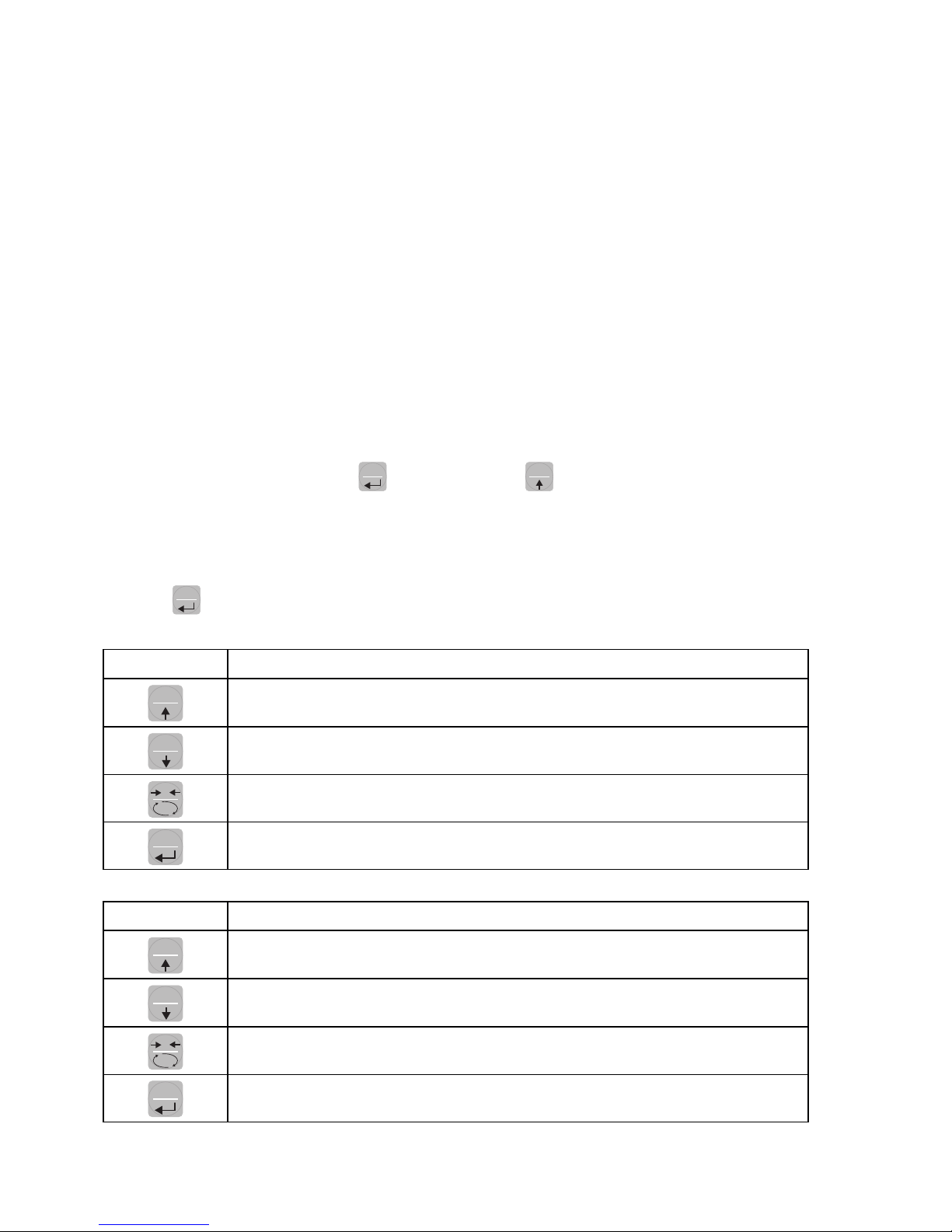
KEY FUNCTION DURING THE MAIN MENU PROGRAMMING
SET It selects the next menu.
FUN It selects the previous menu.
0It exits the programming menu or returns to the upper level.
PRG It accesses the corresponding sub-menu or programming or confirms the selected
parameter.
KEY FUNCTION WHEN SETTING THE NUMERICAL VALUES
SET It increases the value of the flashing digit.
FUN It decreases the value of the flashing digit.
0It goes to the next digit.
PRG It confirms and store the displayed value.

Page 17
KEY FUNCTION WHEN SETTING THE PROSED VALUES
SET It selects the next value.
FUN It selects the previous value.
PRG It confirms and store the displayed value.
The menu parameters can assume values that can be set or selected.
NOTE To exit and save the modified data, press multiple times the
0
key until the indicator returns
to the operating mode.
Page 18
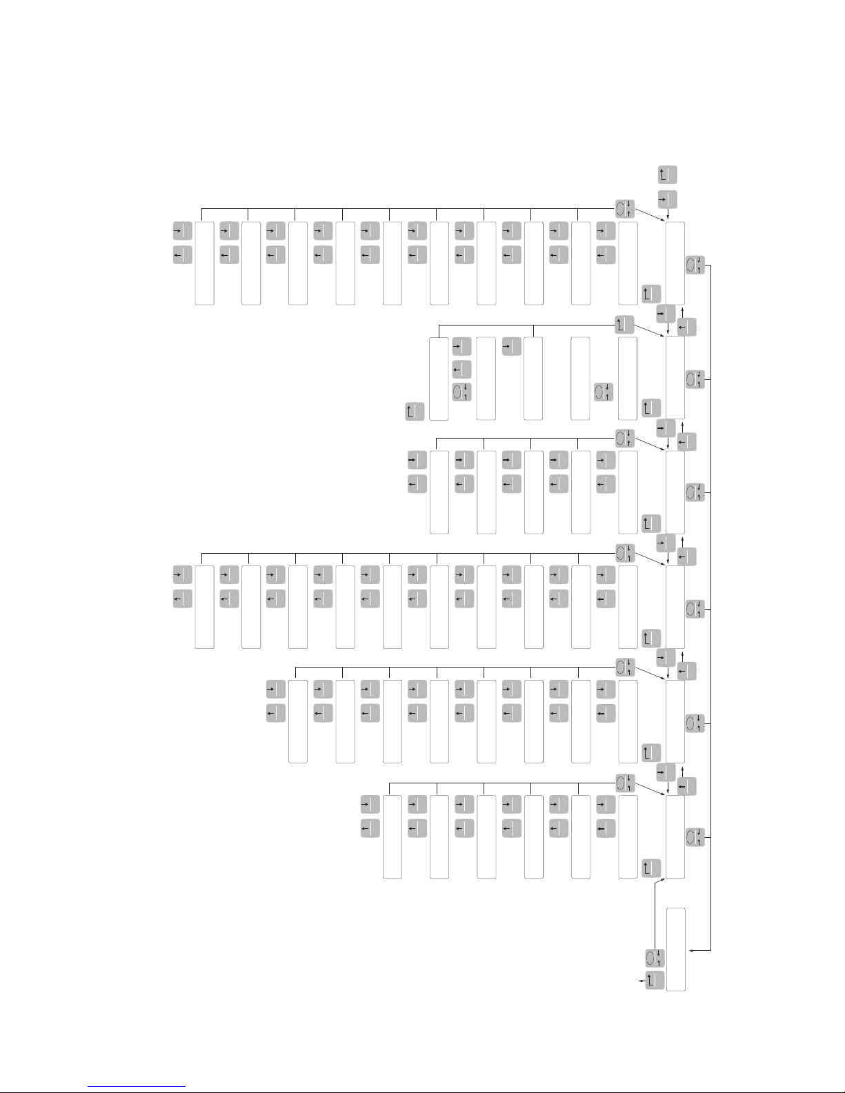
DIAGRAM OF THE MENU
Conf1G
CapaC
SEns1t
nEt
dEad L
dspd1J
S1GnaL
CoUnts
opNodE
UpLoad
dnLoad
CaL1br ParaN
fILtEr
Notion
auto 0
0 trac
0 band
1n-oUt
NodE 1
Hyst-1
t1NEr1
dELay1
NodE 2
Hyst-2
t1NEr2
dELay2
tEst1n
tstoUt
SEr1aL
baUd r
Prot-1
prot-2
AddrEs
Pr-Add
dELay
rEN-Co
data F
AnaLoG
f-sCaL
NodE
AnzEro
tEst
ranGE
OffsEt
StorE?
CaL
0
CaL
123456
60000
+
3 sec.
EXIT MENU
ENTER MENU 0
PRG
PRG
SET SET
FUN
SET
FUN
SET
FUN
SET
FUN
SET
FUN
FUN
0 0 0 0 0
00 0 00
PRG
0
PRG PRG PRG PRG PRG
SET SET FUN SET FUN SET FUN SET FUN
SET FUN
SET FUN
SET FUN
SET FUN
SET FUN
SET FUN
SET FUN
FUNSET
SET FUN
SET FUN
SET FUN
SET FUN
SET FUN
SET FUN
SET FUN
SET FUN
SET FUN
SET FUN
SET FUN
SET FUN
SET FUN
SET FUN
SET FUN
SET FUN
SET FUN
SET FUN
SET FUN
SET FUN
SET FUN
SET FUN
SET FUN
SET FUN
SET FUN
SET FUN
FUN
PRG
0
0
PRG
SET
SET
This manual suits for next models
3
Table of contents
Other Pavone Sistemi Accessories manuals

Popular Accessories manuals by other brands

ORION TELESCOPES & BINOCULARS
ORION TELESCOPES & BINOCULARS Tabletop Equatorial Mount 9009 instruction manual

PASCO
PASCO PS-3204 Product guide

DURAVANT
DURAVANT QC Conveyors PF22 Installation, operation & maintenance instructions

inventum
inventum HNL4212Z manual

MONARCH INSTRUMENT
MONARCH INSTRUMENT SLS-115 instruction manual

Dancover
Dancover AW148011 manual


1M2M
1M2M ED 16 Series installation manual

TrueLife
TrueLife HeatBlanket 1813 user manual

FAAFTECH
FAAFTECH FT-RC-AUD10 installation manual

IV Produkt
IV Produkt NEW EcoCooler Operation and maintenance

MK
MK GUF-P 2000 BC 1500/200 Translation of original instruction manual

Prodipe
Prodipe Studio 22 Pro user manual