PAW DN 32 User manual

PAW GmbH & Co. KG
Böcklerstr. 11, D-31789 Hameln
Phone: +49-5151-9856-0, Fax: +49-5151-9856-98
2017/01 993x4203-mub-ml –V01 1
Montage- und Bedienungsanleitung
Hydraulische Weichen DN 25 / DN 32
Installation and Operation Instructions
Hydraulic Separators DN 25 / DN 32
Notice de montage et d'utilisation
Découpleurs hydrauliques DN 25 / DN 32
Manual de instrucciones para el montaje y manejo
Conmutadores hidráulicos DN 25 / DN 32
Manuale di installazione ed uso
Separatori idraulici DN 25 / DN 32
DN 32
DN 25

1Allgemeines
2 993x4203-mub-ml –V01 2017/01
Art. Nr. / Item no. / N° d'article / Nº de art. / Cod. art. 993x4203-mub-ml
Version / Versión / Versione V01
Technische Änderungen vorbehalten!
We reserve the right to make technical changes without notice!
Sous réserve de modifications techniques !
¡Sujeto a modificaciones técnicas!
Con riserva di modifiche tecniche!
Printed in Germany –Copyright by PAW GmbH & Co. KG
PAW GmbH & Co. KG
Böcklerstraße 11
D-31789 Hameln, Germany

1Allgemeines
2017/01 993x4203-mub-ml –V01 3
eutsch
Inhaltsverzeichnis
1Allgemeines ....................................................................................................................4
1.1 Geltungsbereich der Anleitung ..................................................................................... 4
1.2 Bestimmungsgemäße Verwendung.............................................................................. 4
2Sicherheitshinweise.........................................................................................................5
3Funktion..........................................................................................................................6
4Montage [Fachmann].......................................................................................................7
5Lieferumfang [Fachmann] ................................................................................................9
5.1 Ersatzteile DN 25 (Artikelnummer 344203) ................................................................ 10
5.2 Ersatzteile DN 32 (Artikelnummer 374203) ................................................................ 10
6Technische Daten .........................................................................................................11

1Allgemeines
4 993x4203-mub-ml –V01 2017/01
1Allgemeines
Lesen Sie diese Anleitung vor der Installation und Inbetriebnahme sorgfältig durch.
Bewahren Sie diese Anleitung zum späteren Gebrauch in der Nähe der Anlage auf.
1.1 Geltungsbereich der Anleitung
Diese Anleitung beschreibt die Funktion, Installation und Inbetriebnahme der hydraulischen
Weichen DN 25 und DN 32. Die mit [Fachmann] bezeichneten Kapitel richten sich
ausschließlich an den Fachhandwerker.
1.2 Bestimmungsgemäße Verwendung
Die hydraulische Weiche darf nur in Heizungskreisen unter Berücksichtigung der
in dieser Anleitung angegebenen technischen Grenzwerte verwendet werden.
Die hydraulische Weiche darf nicht in Trinkwasseranwendungen eingesetzt werden.
Die bestimmungswidrige Verwendung der hydraulischen Weiche führt zum Ausschluss
jeglicher Haftungsansprüche.
Verwenden Sie ausschließlich PAW-Zubehör in Verbindung mit der hydraulischen Weiche.
Die Verpackungsmaterialien bestehen aus recycelbaren Materialien und können dem normalen
Wertstoffkreislauf wieder zugeführt werden.

2Sicherheitshinweise
2017/01 993x4203-mub-ml –V01 5
2Sicherheitshinweise
Die Installation und Inbetriebnahme sowie der Anschluss der elektrischen Komponenten setzen
Fachkenntnisse voraus, die einem anerkannten Berufsabschluss als Anlagenmechaniker/in
für Sanitär-, Heizungs- und Klimatechnik bzw. einem Beruf mit vergleichbarem Kenntnisstand
entsprechen [Fachmann].
Bei der Installation und Inbetriebnahme muss folgendes beachtet werden:
einschlägige regionale und überregionale Vorschriften
Unfallverhütungsvorschriften der Berufsgenossenschaft
Anweisungen und Sicherheitshinweise dieser Anleitung
VORSICHT
Personen- und Sachschaden!
Die hydraulische Weiche ist nur geeignet für den Einsatz in Heizungskreisen
mit Heizungswasser gemäß VDI 2035 / Ö-Norm H 5195-1.
Die hydraulische Weiche darf nicht in Trinkwasseranwendungen eingesetzt
werden.
ACHTUNG
Sachschaden durch Mineralöle!
Mineralölprodukte beschädigen die EPDM-Dichtungselemente nachhaltig, wodurch die Dicht-
eigenschaften verloren gehen. Für Schäden, die durch derartig beschädigte Dichtungen
entstehen, übernehmen wir weder eine Haftung noch leisten wir Garantieersatz.
Vermeiden Sie unbedingt, dass EPDM mit mineralölhaltigen Substanzen in Kontakt
kommt.
Verwenden Sie ein mineralölfreies Schmiermittel auf Silikon- oder Polyalkylenbasis,
wie z. B. Unisilikon L250L und Syntheso Glep 1 der Firma Klüber oder Silikonspray.

3Funktion
6 993x4203-mub-ml –V01 2017/01
3Funktion
Hydraulische Weichen werden eingesetzt, wenn in einer Anlage gleichzeitig ein bzw. mehrere
Wärmeerzeuger-/Primärkreise mit eigener Pumpe und ein oder mehrere Verbraucher-
/Sekundärkreise mit Verteilerpumpe vorhanden sind. In so einer Anlage ergeben sich
Betriebsbedingungen, bei denen sich die Pumpen gegenseitig beeinflussen und dabei
in den Kreisläufen ungewollte Veränderungen der Durchsatzleistungen und Förderhöhen
hervorrufen. Die hydraulische Weiche bildet eine hydraulische Entkopplung der
angeschlossenen Kreise. So ist es möglich, die angeschlossenen Primär- und
Sekundärkreise hydraulisch unabhängig zu gestalten. Bei richtiger Auslegung der
hydraulischen Weiche verursacht der Durchfluss in einem Kreis keinen Durchfluss
im anderen Kreis.
Der Einsatz einer hydraulischen Weiche bedingt, dass sowohl der Primär- als auch der
Sekundärkreis mit einer eigenen Pumpe ausgestattet sein müssen! Dadurch kann man
einen Wärmeerzeuger-/Primärkreis mit gleichbleibender Durchsatzleistung und einen
Verbraucher-/Sekundärkreis mit variabler Leistung betreiben: Funktionsbedingungen,
die für moderne Heizungs- und Klimaanlagen typisch sind.
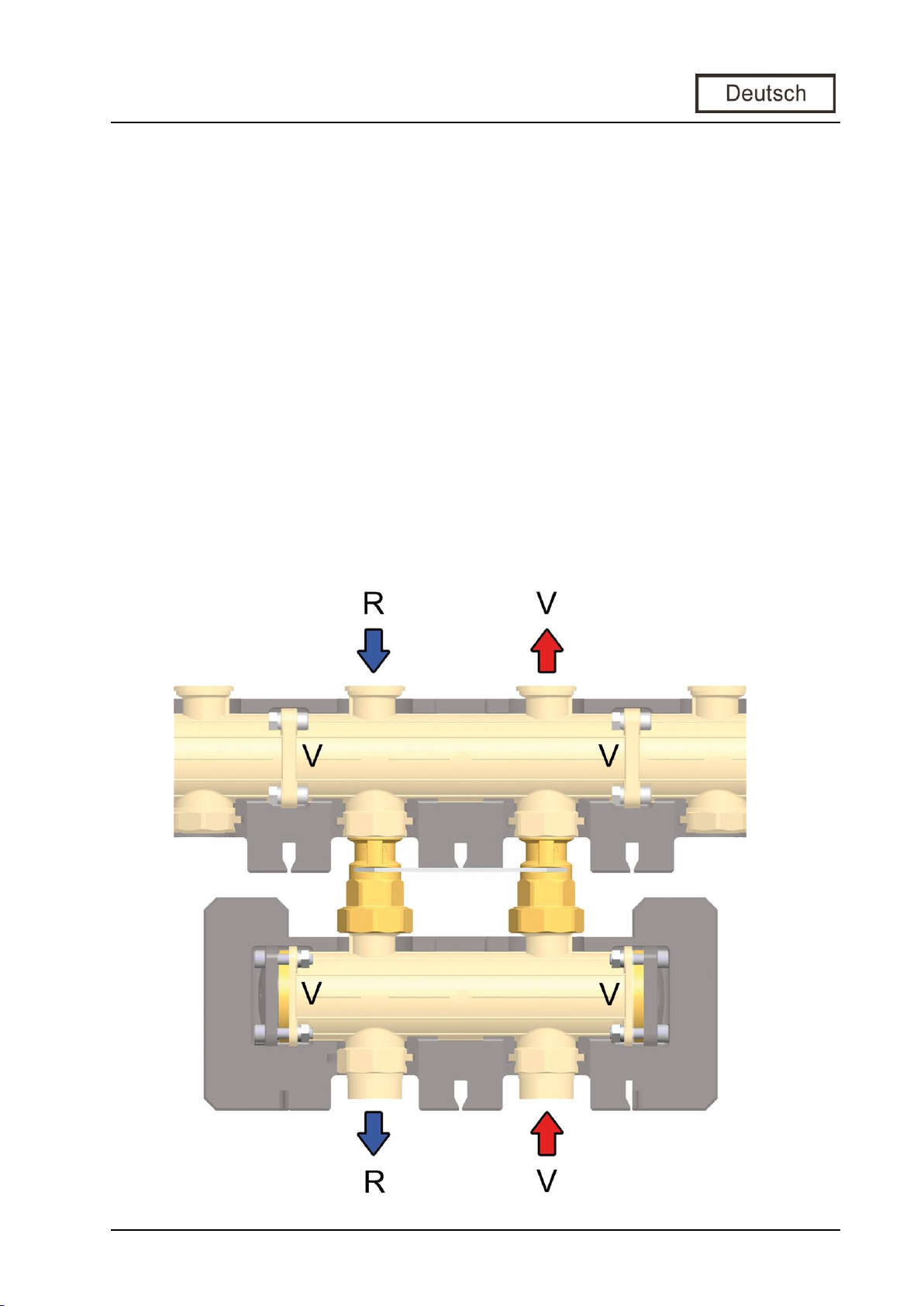
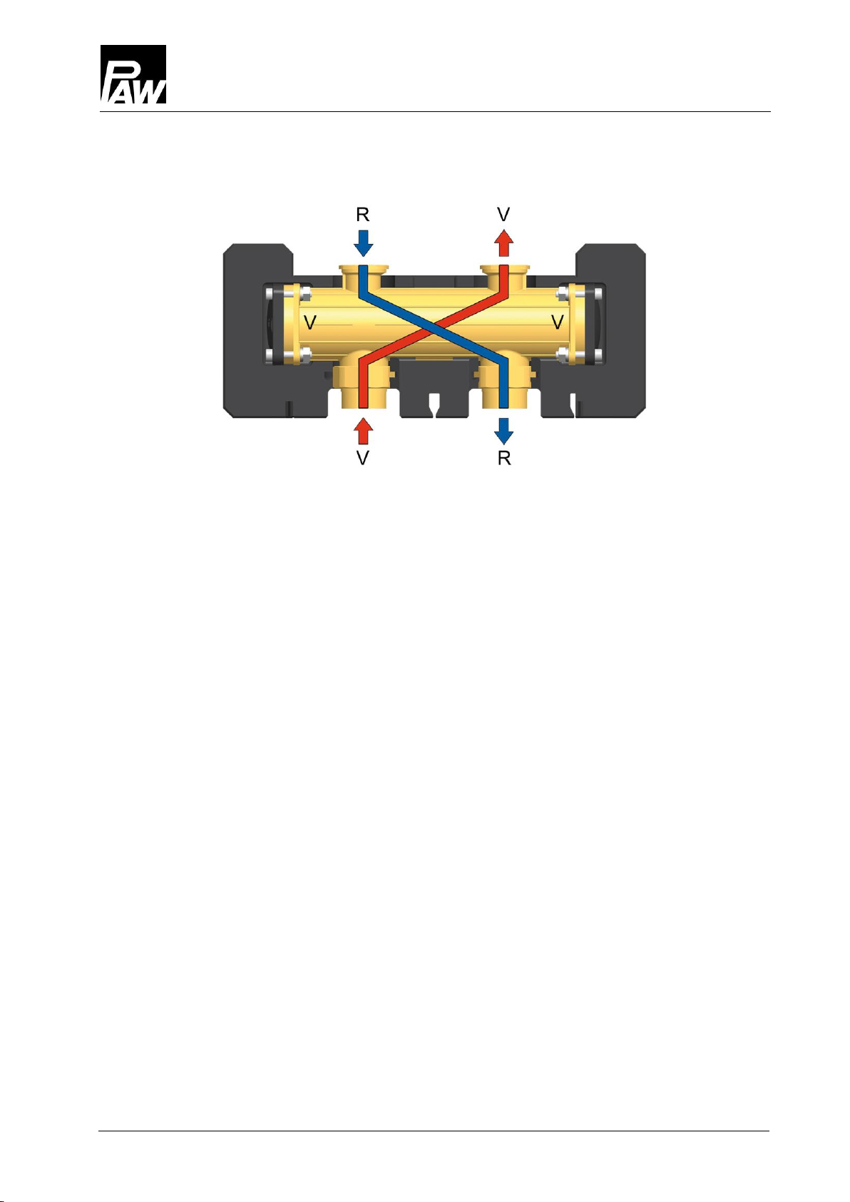
Die hydraulische Weiche von PAW erfüllt alle diese Anforderungen, hat aber dennoch
einen "geführten" Vor- und Rücklauf!
Die hydraulische Weiche hat im Inneren eine Vorlauf- und eine Rücklaufkammer.
Vorlauf und Rücklauf verlaufen über Kreuz.
Die Distanzringe am rechten und linken Ende stellen eine Verbindung von Vorlauf- und
Rücklaufkammer her.

4Montage [Fachmann]
2017/01 993x4203-mub-ml –V01 7
4Montage [Fachmann]
Montagemöglichkeiten:
Sie können die hydraulische Weiche unter einem einzelnen Modulheizkreis montieren.
Sie können die hydraulische Weiche separat im Rohr montieren.
In diesem Fall benötigen Sie zusätzlich
für DN 25: 2 Verschraubungssätze, PAW-Artikelnummer 2151
für DN 32: 2 Verschraubungssätze, PAW-Artikelnummer 2152
Sie können die hydraulische Weiche unter einem Modulverteiler montieren
(siehe untenstehende Abbildung). Dazu benötigen Sie zusätzlich
für DN 25: 1 Halteplatte, PAW-Artikelnummer 3425
für DN 32: 1 Halteplatte, PAW-Artikelnummer 3725
Sie können die hydraulische Weiche auch senkrecht montieren.

4Montage [Fachmann]
8 993x4203-mub-ml –V01 2017/01
Beachten Sie, dass der Vorlauf an den mit "V" markierten Anschlussstutzen angeschlossen
werden muss, der Rücklauf an den mit "R" markierten Anschlussstutzen. Vorlauf und Rücklauf
verlaufen über Kreuz (siehe Abbildung).
Alle mit "V" bezeichneten Stutzen sind mit der Vorlaufkammer verbunden, alle mit "R"
bezeichneten Stutzen sind mit der Rücklaufkammer verbunden.
Vorlauf
Vorlauf
Rücklauf
Rücklauf
Kesselanschluss
Heizkreisanschluss

5Lieferumfang [Fachmann]
2017/01 993x4203-mub-ml –V01 9
Bei der senkrechten Montage müssen Sie den Vorlaufanschluss des Heizkreises
(Verbrauchers) oben anschließen und –entsprechend der Anordnung der Kammern
im Verteilermodul –den Kesselvorlauf unten anschließen (siehe unten). Nur so ist eine
einwandfreie Funktion gewährleistet.
5Lieferumfang [Fachmann]
HINWEIS
Reklamationen und Ersatzteilanfragen/-bestellungen werden ausschließlich unter Angabe
der Seriennummer bearbeitet!
Die Seriennummer befindet sich auf der hydraulischen Weiche.
Rücklauf
Rücklauf
Vorlauf
Vorlauf
Heizkreisanschluss
Kesselanschluss

5Lieferumfang [Fachmann]
10 993x4203-mub-ml –V01 2017/01
5.1 Ersatzteile DN 25 (Artikelnummer 344203)
5.2 Ersatzteile DN 32 (Artikelnummer 374203)

6Technische Daten
2017/01 993x4203-mub-ml –V01 11
6Technische Daten
Hydraulische Weiche
DN 25
DN 32
Abmessungen
Rohranschluss unten
1½" AG / 1" IG
2" AG / 1¼" IG
Rohranschluss oben
1" PAW-Flansch
1¼" PAW-Flansch
Achsabstand
(Vorlauf / Rücklauf)
125 mm
125 mm
Einbauhöhe
128 mm
156 mm
Breite
375 mm
375 mm
Technische Daten
Max. zulässiger Druck
6 bar
6 bar
Max. zulässige Temperatur
110 °C (kurzzeitig 130 °C)
Empfohlener Einsatzbereich bis:
1600 l/h
2600 l/h
Werkstoffe
Fittings / Gehäuse
Messing
O-Ringe / Dichtungen
EPDM
Isolierung
EPP

1General information
2017/01 993x4203-mub-ml –V01 B-1
BEnglish
Contents
1General information ..................................................................................................... B-2
1.1 Scope of these instructions ...................................................................................... B-2
1.2 Designated use ........................................................................................................ B-2
2Safety instructions ....................................................................................................... B-3
3Function...................................................................................................................... B-4
4Assembly [specialist] ................................................................................................... B-5
5Scope of delivery [specialist]........................................................................................ B-7
5.1 Spare parts DN 25 (Item number 344203)................................................................ B-8
5.2 Spare parts DN 32 (Item number 374203)................................................................ B-8
6Technical data............................................................................................................. B-9

1General information
B-2 993x4203-mub-ml –V01 2017/01
1General information
Carefully read these instructions before installation and commissioning.
Save these instructions in the vicinity of the installation for future reference.
1.1 Scope of these instructions
These instructions describe the installation, commissioning, function and operation of the
hydraulic separators DN 25 and DN 32. The chapters called [specialist] are intended for
specialists only.
1.2 Designated use
The hydraulic separators may only be used in heating circuits taking into consideration
the technical limit values indicated in these instructions.
The heating circuit must not be used in domestic water applications.
Improper usage excludes any liability claims.
Only use PAW accessories in combination with the hydraulic separator.
The wrapping materials are made of recyclable materials and can be disposed of
with recyclable materials.

2Safety instructions
2017/01 993x4203-mub-ml –V01 B-3
2Safety instructions
The installation and commissioning of the solar station as well as the connection of electrical
components require technical knowledge commensurate with a recognised vocational
qualification as a fitter for plumbing, heating and air conditioning technology, or a profession
requiring a comparable level of knowledge [specialist].
The following must be observed during installation and commissioning:
Relevant local and national prescriptions
Accident prevention regulations of the professional association
Instructions and safety instructions mentioned in this manual
CAUTION
Personal injury and damage to property!
The hydraulic separator must only be used in heating ciruits filled
with heating water according to VDI 2035 / Ö-Norm H 5195-1.
The distribution manifold must not be used in domestic water applications.
NOTICE
Material damage due to mineral oils!
Mineral oil products cause lasting damage to seals made of EPDM, whereby the sealant
properties get lost. We do not assume liability nor provide warranty for damage to property
resulting from sealants damaged in this way.
It is imperative to avoid that EPDM gets in contact with substances containing
mineral oils.
Use a lubricant based on silicone or polyalkylene and free of mineral oils, such as
Unisilikon L250L and Syntheso Glep 1 of the Klüber company or a silicone spray.

3Function
B-4 993x4203-mub-ml –V01 2017/01
3Function
Hydraulic separators are used when there are one or more heat generation circuits/primary
circuits with pump and one or more consumer/secondary circuits with distribution pump in
one system. Due to the working conditions in such systems, pumps affect each other and
changes in throughput and delivery height can occur. The hydraulic separator causes a
neutralization of the connected circuits. Thus, the primary and secondary circuit can work
independently. With a correct dimensioning of the hydraulic separator, the flow in one circuit
does not cause any flow in the other circuit.
When a hydraulic separator is used, each circuit (the primary and the secondary circuit) must
be equipped with a pump! Thus, a boiler circuit/primary circuit can be provided with constant
throughput and a consumer circuit/secondary circuit can be provided with variable flow.
These are the typical functioning conditions for modern heating and air conditioning systems.
The PAW hydraulic separator fulfills these requirements, but has a "guided" flow and return
line!
The hydraulic separator has a flow and a return chamber.
The flow and the return cross each other.
The distance rings at the right and left end connect the flow and return chamber.

4Assembly [specialist]
2017/01 993x4203-mub-ml –V01 B-5
4Assembly [specialist]
Assembly positions:
The hydraulic separator can be installed under an individual heating circuit.
The hydraulic separator can be installed separately in the pipe.
In this case, additional accessories are needed:
for DN 25: 2 connection sets, PAW item no. 2151
for DN 32: 2 connection sets, PAW item no. 2152
The hydraulic separator can be installed under a distribution manifold (see figure below).
In this case, additional accessories are needed:
for DN 25: 1 mounting plate, PAW item no. 3425
for DN 32: 1 mounting plate, PAW item no. 3725
The hydraulic separator can also be installed vertically.

4Assembly [specialist]
B-6 993x4203-mub-ml –V01 2017/01
Keep in mind that the flow is connected to the pipe connection marked "V" and the return
is connected to the pipe connection marked "R". The flow and the return cross each other
(see figure).
All connections marked "V" must be connected to the flow chamber, all connections marked "R"
must be connected to the return chamber.
Flow
Flow
Return
Return
Boiler connection
Heating circuit connection

5Scope of delivery [specialist]
2017/01 993x4203-mub-ml –V01 B-7
When the hydraulic separator is mounted vertically, the flow line to the heating circuit must be
connected to the upper connection and the flow line from the boiler must be connected to the
lower connection (see below). Only in this way, an optimum function can be guaranteed.
5Scope of delivery [specialist]
NOTICE
Complaints and requests/orders of spare parts will only be processed with information on the
serial number!
The serial number is placed on the hydraulic separator.
Return
Return
Flow
Flow
Heating circuit connection
Boiler connection

5Scope of delivery [specialist]
B-8 993x4203-mub-ml –V01 2017/01
5.1 Spare parts DN 25 (Item number 344203)
5.2 Spare parts DN 32 (Item number 374203)

6Technical data
2017/01 993x4203-mub-ml –V01 B-9
6Technical data
Hydraulic separator
DN 25
DN 32
Dimensions
Pipe connections bottom
1½" ext. thread/
1" int. thread
2" ext. thread/
1¼" int. thread
Pipe connections top
1" PAW flange
1¼" PAW flange
Centre distance (flow / return)
125 mm
125 mm
Installation height
128 mm
156 mm
Width
375 mm
375 mm
Technical data
Maximum permissible pressure
6 bars
6 bars
Max. permissible temperature
110 °C,
short-term 130 °C
110 °C,
short-term 130 °C
Recommended range
of application up to
1 600 l/h
2 600 l/h
Materials
Fittings / body
Brass
O-rings / gaskets
EPDM
Insulation
EPP
This manual suits for next models
1
Table of contents
Languages:
Popular Water Filtration System manuals by other brands

Parker
Parker TGE 308 operating instructions

Oase
Oase Filtral 2500 UVC operating instructions

Cisco
Cisco Nexus 7000 Series Replacement instructions

Master Water Conditioning
Master Water Conditioning Alliance MP-MCA Series Installation and operation manual

Premier
Premier WP-5 Nstallation, operation and maintenance manual

Hagen
Hagen ELITE JET-FLO 50 user manual