Payter APO01 PAY V1-X Series User manual
User Manual
V1.3 - 202301
Page 1 of 43
Payter B.V.
Rozenlaan 115
3051 LP Rotterdam
The Netherlands

User Manual
V1.3 - 202301
Page 2 of 43
Apollo terminal series
User manual v1.3 (2023-01-10)
Copyright © 2023 PAYTER B.V.
All rights reserved.
Payter reserves the right to modify specifications stated in this manual.
Liability
Payter B.V. accepts no liability for claims arising from improper use other than that stated in this
manual of from not obeying (safety) instructions and precautions in this manual. Although
considerable care has been taken to ensure a correct and suitably comprehensive description of
the product, this manual may nonetheless contain errors and inaccuracies.
Warranty
Payter B.V. warrants to the original purchaser that this product is free from defects in material or
workmanship for the period of one year from the date of purchase. This warranty does not apply
to damage incurred due to misuse, incorrect handling, unapproved repairs or unapproved
alterations.
How to contact us
If you have any comments or queries concerning any aspect related to the product, do not
hesitate to contact us:
Payter B.V.
Rozenlaan 115
3051 LP Rotterdam
t +31 (0)8 54 01 23 80

User Manual
V1.3 - 202301
Page 3 of 43
About this manual
This manual is intended for professionals responsible for the integration, installation,
configuration or problem solving of the Apollo and/or ApolloMax terminal.
What you need to know
You will have a better understanding of how the terminal works if you are familiar with:
−Ethernet network technologies
−The MDB protocol
Reference documents
Professionals responsible for configuration or installation may also refer to:
−Response code and error list
−Payter session protocol document
−Payter Cloud Payments Service document
Professionals responsible for integration of the Apollo terminal into the host machine, may also
refer to:
−Mechanical integration manual
You can find request these additional documents at through your account representative or via
To ensure proper operation, read this manual thoroughly before using the product
and retain the information for future reference.
User Manual
V1.3 - 202301
Page 4 of 43
Terms and abbreviations
Abbreviation
Description
3G/4G
Third / Fourth Generation (i.e. a mobile communication system)
APN
Access Point Name
CCI
Coffee Credit Interface
DC
Direct Current
DHCP
Dynamic Host Control Protocol
DNS
Domain Name Server
EMV
Europay Mastercard Visa
EVA
European Vending Association
GPRS
General Packet Radio Service (i.e. a mobile communication system)
GSM
Global System for Mobile communication
HSPA
High Speed Packet Access (i.e. a mobile communication system)
IP
Internet Protocol
LAN
Local Area Network
MDB
Multidrop Bus (i.e. a communications bus standard for vending machines).
ms
Milliseconds
NAMA
National Automatic Merchandising Association
NFC
Near Field Communication
PSP
Payment Service Provider
QR
Quick Response
PVP
Payter Vending Protocol
RTP
Remote Terminal Protocol
SDK
Software Development Kit
SIM
Subscriber Identification Module
USB
Universal Serial Bus
VMC
Vending Machine Controller
PCI
Payment Card Industry Security Standards Council
SRED
Secure reading and exchange of data
DUKPT
Derived Unique Key per Transaction
AES
Advanced Encryption Standard
TDES
Triple - Data Encryption Standard
RSA
Rivest, Shamir, & Adleman Algorithm
SHA
Secure Hash Algorithm
HMAC
Hash-Based Message Authentication Code
CMAC
Cipher-Based Message Authentication Code
User Manual
V1.3 - 202301
Page 5 of 43
Table of Contents
1. Introduction.......................................................................................................7
2. Safety.................................................................................................................8
Safety symbols....................................................................................................................... 8
AC Adapter ............................................................................................................................ 8
Terminal ................................................................................................................................ 8
Security.................................................................................................................................. 8
3. The Apollo Terminal ...........................................................................................9
Package contents .................................................................................................................. 9
Supported cards schemes ..................................................................................................... 9
Apollo terminal.................................................................................................................... 10
ApolloMax terminal............................................................................................................. 11
Connections......................................................................................................................... 12
Contactless Card Reader ..................................................................................................... 12
Power connection ............................................................................................................... 13
Dimensions Power supply ................................................................................................... 13
Accessories.......................................................................................................................... 13
Dimensions Antenna ........................................................................................................... 14
Installation........................................................................................................................... 14
Placing the antenna............................................................................................................. 14
4. Interfaces, connections and terminal configuration..........................................15
Internet connection............................................................................................................. 15
5. Modes of operation..........................................................................................16
Machine Interface ............................................................................................................... 16
MDB mode .......................................................................................................................... 16
6. Internet connection..........................................................................................17
Firewall network settings for the Payter Payment Terminal............................................... 17
7. User Interface ..................................................................................................18
Customisation ..................................................................................................................... 18
Example Payment flow........................................................................................................ 18
8. Configuration ...................................................................................................19
Access.................................................................................................................................. 19
9. Mechanical Integration ....................................................................................20
Front mounting ................................................................................................................... 20
EVA mounting...................................................................................................................... 21
9.2.1 Device opening.................................................................................................................... 21
9.2.2 EVA mounting option 1: studs in machine.......................................................................... 22
9.2.3 EVA mounting option 2: no studs in machine..................................................................... 23
Dimensions Apollo terminal................................................................................................ 24
Dimensions ApolloMax terminal......................................................................................... 25
10. Merchant Responsibilities Security...................................................................26
Receipt and Storage ............................................................................................................ 26
Deployment......................................................................................................................... 26
Transactions and reconciliation .......................................................................................... 27
Usage and Management ..................................................................................................... 27
Battery and storage............................................................................................................. 27
Security................................................................................................................................ 27
Faulty, lost, stolen, or damaged/tampered Terminals........................................................ 28
11. PCI Security ......................................................................................................29
Model Name and Appearance ............................................................................................ 29
Product Type ....................................................................................................................... 29
Identification....................................................................................................................... 29
11.3.1 Hardware............................................................................................................................. 29
11.3.2 Firmware ............................................................................................................................. 30
Location of Identifiers ......................................................................................................... 30
User Manual
V1.3 - 202301
Page 6 of 43
Installation and User Guidance ........................................................................................... 30
11.5.1 Initial Inspection.................................................................................................................. 30
11.5.2 Installation........................................................................................................................... 30
Environmental Conditions................................................................................................... 31
Communications and Security Protocols ............................................................................ 31
Configuration Settings......................................................................................................... 31
12. Operation and Maintenance.............................................................................31
Periodic Inspection.............................................................................................................. 31
Self-Test............................................................................................................................... 31
Passwords and Certificates ................................................................................................. 32
Tamper Response................................................................................................................ 32
Privacy Shield ...................................................................................................................... 32
Patching and Updating........................................................................................................ 32
Decommissioning ................................................................................................................ 32
13. Security measures ............................................................................................32
Software Development Guidance ....................................................................................... 32
Signing................................................................................................................................. 33
Account-data Protection..................................................................................................... 33
Algorithms Supported ......................................................................................................... 33
Key Management ................................................................................................................ 33
Key Loading ......................................................................................................................... 33
Key Table............................................................................................................................. 33
References........................................................................................................................... 35
14. Technical specifications....................................................................................36
15. Troubleshooting...............................................................................................37
HTTP Error codes................................................................................................................. 37
Creditcall/NMI Error codes.................................................................................................. 38
Issuer Decline Codes ........................................................................................................... 39
16. End-of-life ........................................................................................................39
17. Declaration of Conformity ................................................................................40
18. FCC...................................................................................................................41
Radiofrequency radiation exposure Information:............................................................... 41
Electronic Label ................................................................................................................... 41
19. Family Letter ....................................................................................................42
20. RoHS-3 Certificate of Compliance .....................................................................43
User Manual
V1.3 - 202301
Page 7 of 43
1. Introduction
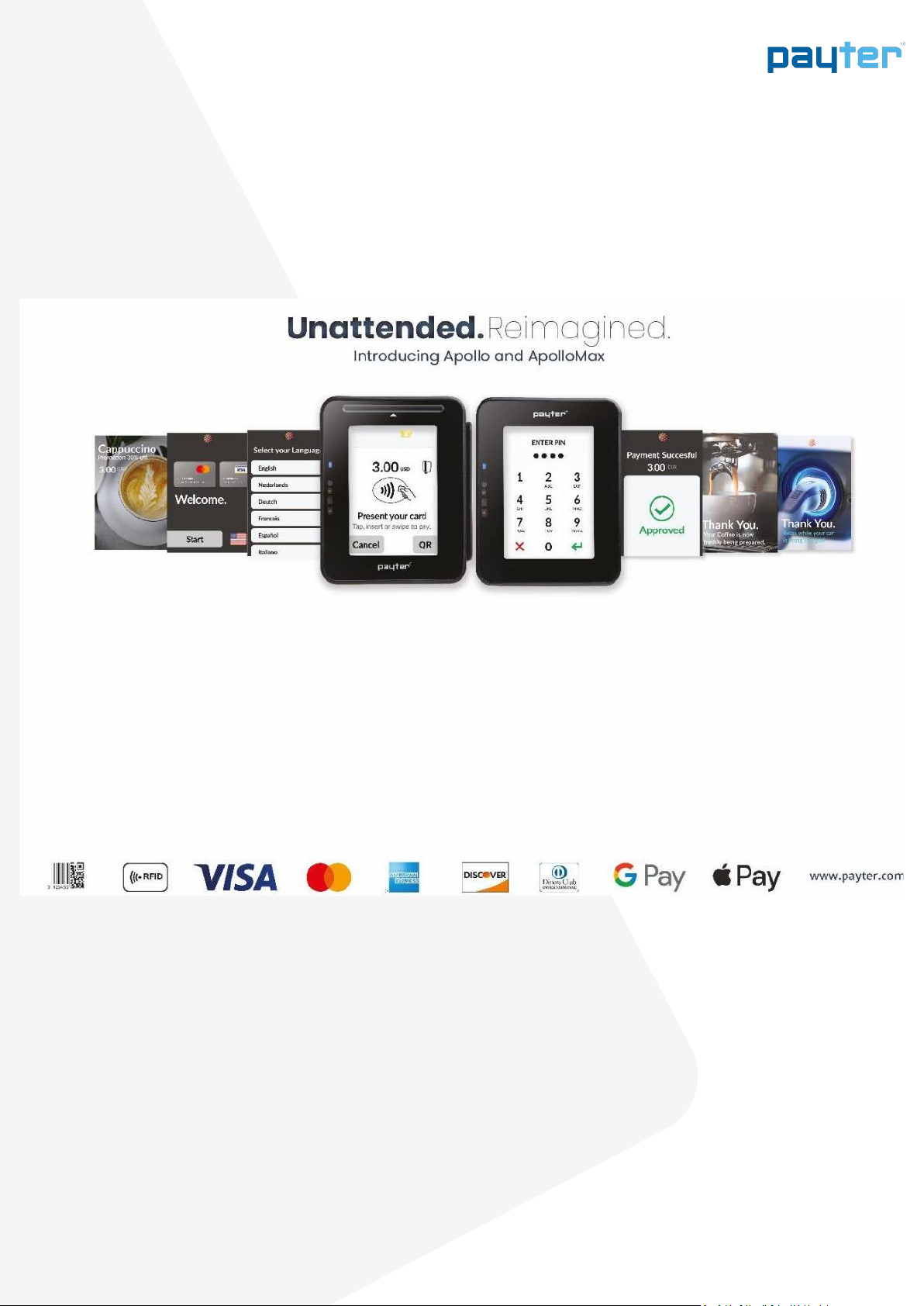
Thank you for choosing an Apollo series payment terminal for your host application. The Apollo
terminals are designed for use in unattended points of sale, such as food and beverage vending
machines, EV-Chargers, parking ticket machines and more.
The terminals support many payment schemes and can be used as a drop-in replacement for an
existing host application, using industry standard interfaces such as multidrop bus (MDB) or
potential free pulse contact. Also available are proprietary interface options (PSP and cloud API)
that use Ethernet, USB or RS232 to connect the Apollo terminal to a host system.
An internet connection to the terminal, required for transaction processing, can be realized by
connecting to a LAN network. If no LAN is available, an optional 4G modem can provide a high-
quality internet connection, ensuring your transaction processing performance will not degrade
because of a low internet speed.
The Apollo terminal series supports reliable remote management functionality for firmware
updates and configuration changes.
Please leave your terminal on and connected to the internet on a regular basis, in
order to make sure that it can be managed properly at any time.
Failure to charge the batteries at notification by the MyPayter Terminal
management System can result in tampering the terminal. A tampered terminal
need to be returned to Payter for analysis, possible replacement of the batteries and
key injection.

User Manual
V1.3 - 202301
Page 8 of 43
2. Safety
Safety symbols
In this manual, safety instructions and precautions are marked with a symbol. Always read and
follow the safety instructions before reading on. This manual uses the following symbols:
Warning!
Risk of (serious) injury to the user or serious damage to the product if the user does
not carefully follow the instructions.
Caution!
Risk of damage to the product if the user does not carefully follow the instructions.
Attention!
A remark meant to point the user to a potential problem.
AC Adapter
•Use only power adapters that come with the terminal.
•Do not use the AC adapter if the cord is damaged.
•Do not disassemble the AC adapter. Only qualified technicians may service
the adapter.
•The AC adapter is intended for indoor use only. Do not expose to rain or
snow.
•Do not use the AC adapter in high-moisture environments.
•Never touch the AC adapter when your hands or feet are wet.
•Do not immerse the AC adapter or the terminal in fluid; these devices are
not waterproof.
Terminal
•Do not place the terminal near electrical appliances or other devices that
cause excessive voltage fluctuations or that emit electrical noise.
•Do not use where there is high heat, direct sunlight, humidity moisture,
caustic chemicals or caustic oils.
Security
All Payter Point of Sale terminals are certified by the card schemes according to the latest
standards and accredited through various acquirers to securely process transactions. The integrity
of the payment terminals is crucial, because they process sensitive card data.
To ensure safe use, prevent fraud and compliance to related Scheme Rules, please follow all
instructions as described in the chapters 10 Merchant Responsibilities Security, 11.5 Installation
and User Guidance and 12 Operation and Maintenance.

User Manual
V1.3 - 202301
Page 9 of 43
3. The Apollo Terminal
The Apollo and ApolloMax are PIN Entry Devices (PED) for payment processing in unattended
environments. The terminals have the ability to provide contact, contactless and magstripe
transactions.
The terminals supports the following main features
•TFT LCD with capacitive touch
•Chip Card Reader
•Contactless Reader
•Magnetic Stripe Reader
•Ethernet
•USB
•Wifi, Blue Tooth
•MDB
•Optional 4G Modem
Package contents
The package contains the following items:
1. Cover plate
2. Terminal
3. Terminal Rubber gasket
4. Rear rubber gasket
5. Mounting frame
6. M4Screws, and bolts set
Figure 1: Components Apollo terminals
Supported cards schemes
The Apollo terminal support the following cards and card schemes.

User Manual
V1.3 - 202301
Page 10 of 43
Apollo terminal
Figure 2: Front of the Apollo terminal
No.
Item
Description
1
LEDs (4)
Multi colour status LEDs
2
Camera and Locator light
Enabling QR-Code reading
3
Proximity sensor
4
WiFi & Bluetooth Module
5
3,5 Inch touch screen
6
Speaker
1
2
4
5
3
6

User Manual
V1.3 - 202301
Page 11 of 43
ApolloMax terminal
Figure 3: Front of the ApolloMax terminal
No.
Item
Description
1
LEDs (4)
Multi colour status LEDs
2
Camera and Locator light
Enabling QR-Code reading
3
Proximity sensor
4
Chip Card Reader
5
WiFi & Bluetooth Module
6
Magnetic Stripe reader
7
3,5 Inch touch screen
8
Speaker
1
2
4
6
8
5
3
7

User Manual
V1.3 - 202301
Page 12 of 43
Connections
Figure 4: Rear side of the Apollo terminal
No.
Item
Description
1
USB-C port
Host and Slave Connector
2
Micro Fit MDB connector
Port to connect with the internet through the LAN.
3
4G/ GPS modem
Modem with GPS functionality (optional)
4
RJ 45 LAN Connector
Port for USB-C cable to interface with the terminal from the
host machine.
5
Antenna connectors
MMCX Connector for 4G Antenna
6
GSSN Connector
Connector for GSSN (GPS) antenna
Contactless Card Reader
The Apollo and ApolloMax have a contactless reader that supports all contactless EMV cards
including ApplePay, Google Pay, ISO14443 Type A & B (T=CL), Mifare Classic, Desfire cards as well
as the ISO18092: NFC Protocol.
Cards and phones are best read when positioned over
the center of the contactless icon.
Antenna Location
Contactless landing Plane Icon
1
3
2
4
5 6
User Manual
V1.3 - 202301
Page 13 of 43
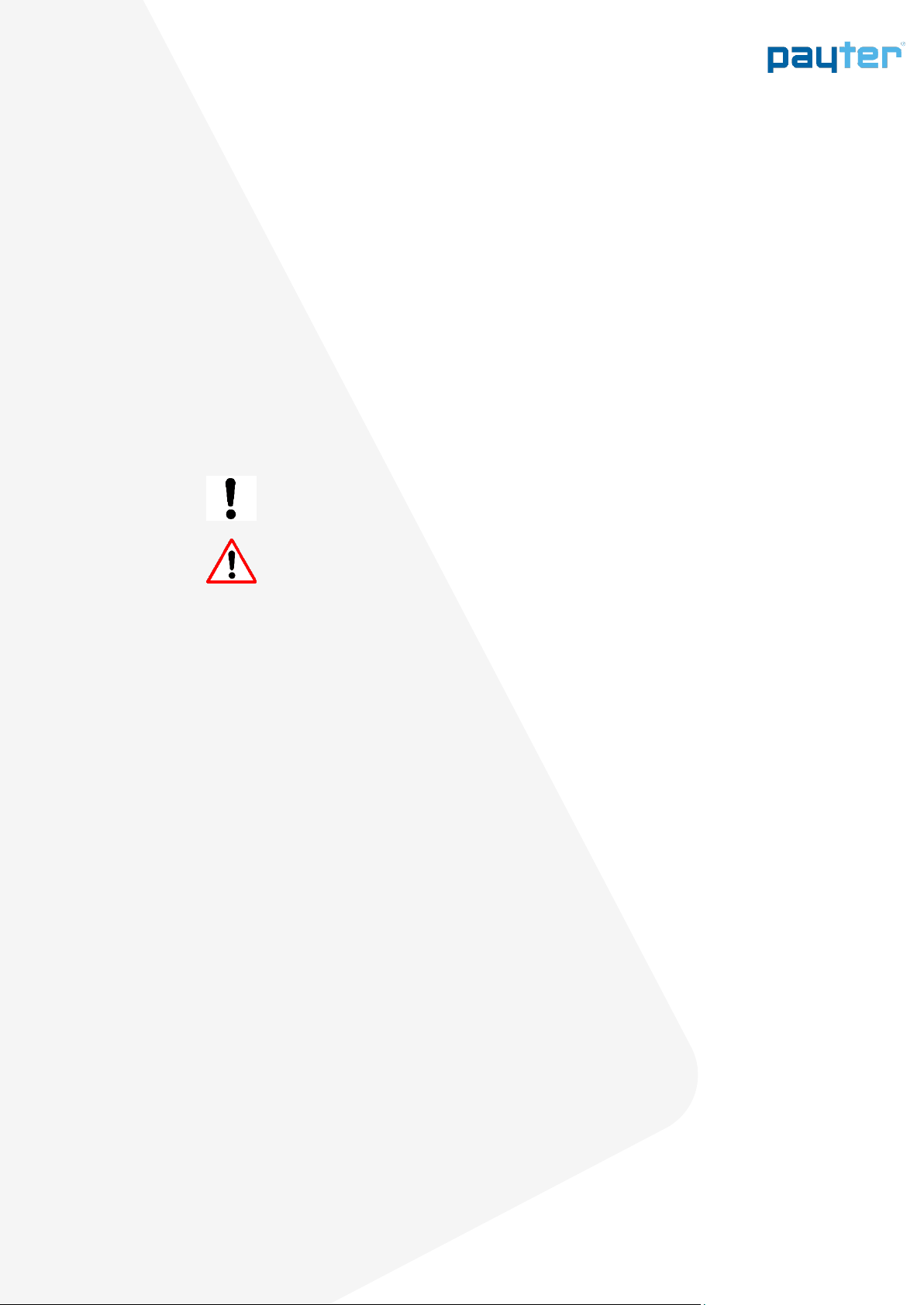
Power connection
The terminals require an external power supply for operation, using two options through the
Micro fit connector:
-Provided 220V power supply
-MDB or similar bus
Please find below the specification for connecting the terminal:
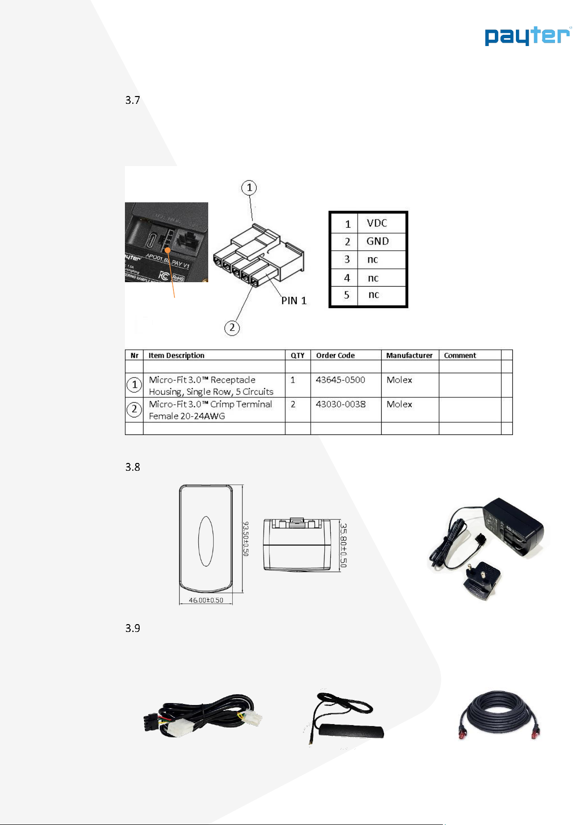
Dimensions Power supply
Accessories
The following accessories are available for integration and connection.
MDB/Power
Cable
LAN Cable
10 meter
Stick on GSM
Antenna
MDB or Power supply
VDC = 12..24V
P = 18W max.
User Manual
V1.3 - 202301
Page 14 of 43
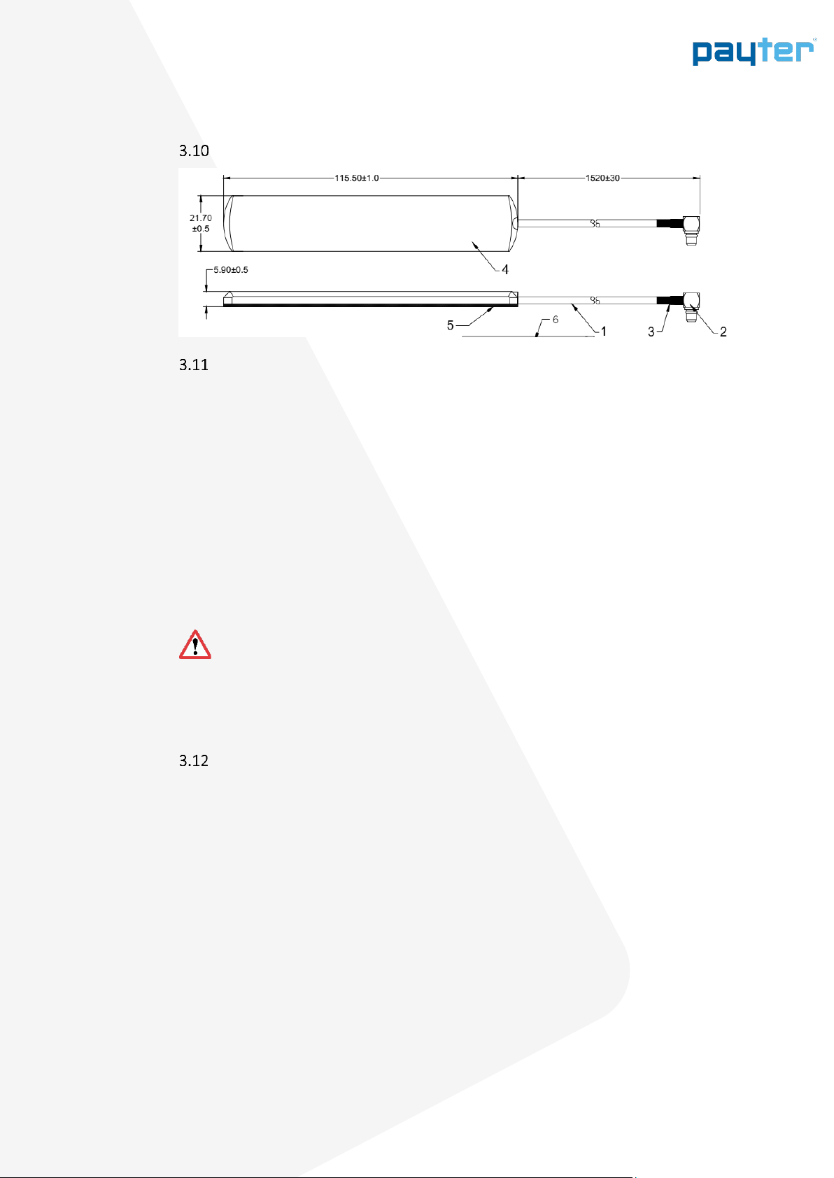
Dimensions Antenna
Installation
Only use cables and mounting materials provided with the terminal, proper function of the
terminals is not guaranteed when 3rd party accessories are used with the exception of the LAN
cable.
-Always place the rubber gasket provided with the terminals
-Do not install the ApolloMax in a position where it is exposed to direct rain or hostile
weather.
-to avoid reflections and guarantee readability, do not expose the display to direct
sunlight
When supporting pin entry
-for the security of the card-holder, make sure that PIN privacy is guaranteed:
-locating the display outside the field of vision of cameras, mirrors and so on, and away
from stairs
-check all local regulations and requirements for PIN privacy
Metal environments will influence the performance of the contactless operating field.
Please ensure that the Apollo terminals are not completely enclosed in a metal
environment otherwise the operating distance will be reduced. An offset of 5 mm along the sides
and rear of the terminal will provide enough distance. If you have any questions with regards to
the mechanical integration, please contact the Payter support desk.
Placing the antenna
1. Place antenna externally for better signal strength. (Recommended)
2. If signal strength is strong inside the machine (2+ bars) internal installation could be
considered..
3. Make sure the antenna is not completely surrounded by metal or mounted on metal.
(reception loss)
4. Use caution when fastening the external antenna cable to MMCX connector on the terminal,
too much force can damage the connection.
You get the Most Consistent & Reliable Results by placing the antenna on top of the machine.
An optional External Mount Dome Antenna can be provided to help with Performance & Security
Things to consider…
•Radio waves move in a straight line between our antenna and the antenna on the cell
tower
•They do not go around obstacles, they go through them if they can
•Glass and wood are no problem but steel and concrete pose a real challenge
•Consider heating ducts, plumbing and other such obstacles

User Manual
V1.3 - 202301
Page 15 of 43
4. Interfaces, connections and terminal configuration
The Apollo terminal series supports various different interfaces to connect to a host machine.
Section Error! Reference source not found. gives an overview of the available interfaces.
For more information on the use of the interfaces and the configuration of the relevant
parameters, see chapter 0.
Interface mode
Description
MDB
Multidrop bus (MDB) is an industry standard for interfacing with vending machines. If your
machine supports an MDB cashless device, then integrating and connecting to the cashless
device is easy, provided that the MDB standard has been implemented properly in your
machine. An advantage of MDB is that the interface also supplies power to the terminal,
requiring no additional power supply.
Executive
The Apollo series terminals can be combined with the VendBox to enable executive mode
functionality. The VendBox is a Payter product and acts as a converter between the
executive and the MDB interface.
Potential Free
Pulse Contact
A configurable potential free pulse contact is available to signal your application that a
payment transaction has been successfully processed. In addition, an input port is available
to enable or disable the terminal, if, for example, the machine is out of order. Although the
potential free pulse contact interface is widely used, there is no standardization and
attention must be paid to electrical details before it can be used.
RTP
The Remote Terminal Protocol (RTP) is used to manage the functionality of the terminal
from your software application from anywhere in a LAN or through a USB connection.
PVP
The message-based Payter Vending Protocol (PVP) provides basic functionality for
machine-to-terminal communication, over an RS232 connection.
CCI
The message-based Coffee Credit Interface (CCI) is used in certain coffee machines and
communicates over RS232.
Table 1: Available host machine interfaces
Internet connection
Table 2 lists the available options to connect the terminal to the internet.
Internet
connection
Description
LAN
A LAN port allows the Apollo series terminals to connect to the internet through a LAN
network.
3G/HSPA modem
If there is no access to a LAN network, a 3G/HSPA modem is optionally available.
Table 2: Available internet connections
User Manual
V1.3 - 202301
Page 16 of 43
5. Modes of operation
Machine Interface
The Apollo terminal family support several different interfaces to connect to your machine.
Choosing an interface will largely depend on the interface that is supported by your machine, and
the preferred method of powering the terminal. Table 1 gives a summary of available options.
Interface
Mode
Description
Remarks
MDB
The Multi Drop Bus is an industry standard interface for vending
machines. If your machine supports an MDB - Cashless Device, then
this will require little effort to reach a working solution, provided that
the MDB standard is correctly implemented in your machine. An
advantage of MDB is that the interface also supplies power to the
terminal, requiring no additional power supply.
PSP
This message based protocol provides basic functionality for machine
to payment terminal communication, over an RS232 or TCP/IP
connection.
Cloud
This API provides methods to manage payment sessions on Payter
terminals, in this mode of operation the terminal is slaved to the Payter
Cloud API.
Potential
Free Pulse
Contact
A configurable potential free pulse contact is available to signal your
application that a payment transaction was successfully processed. In
addition, an input port is available to enable/disable the terminal, if for
example the machine is out of order.
Although a Potential free pulse contact interface is widely used, there
is no standardization, and requires attention to electrical details before
it can be used.
Require Accessory
Table 5.1 –Available Host Machine interface modes.
For detailed and in depth information about the various interfaces, please check the Payter
website for documentation or ask your Payter account representative.
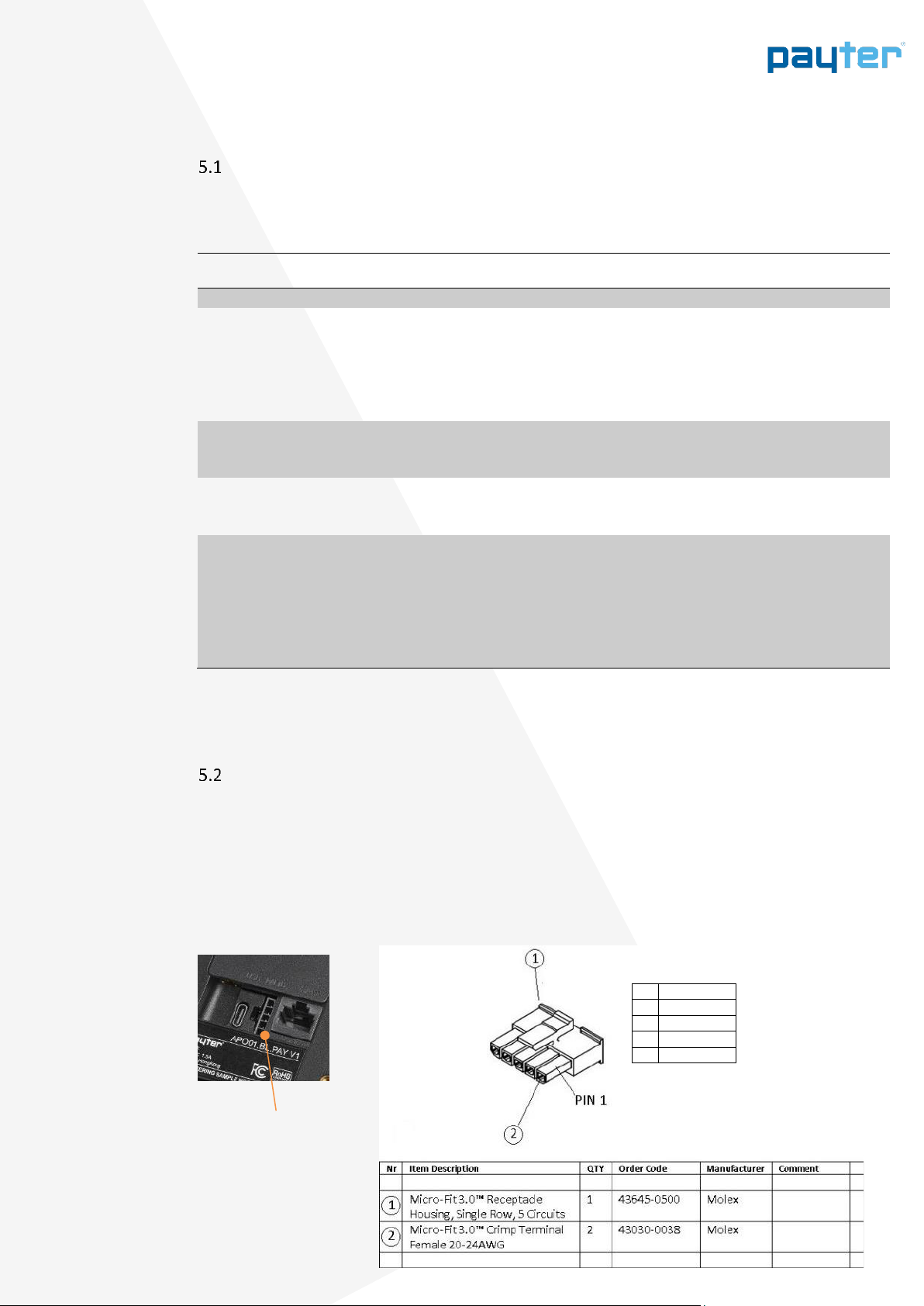
MDB mode
MDB stands for multidrop bus. Since the 1980, the multidrop computer bus has been used by
vending machine controllers to communicate with the vending machine's components, such as a
currency detector. It is now an open standard of the National Automatic Merchandising
Association (NAMA).
The Apollo series terminals are classified as MDB Cashless Devices and support levels 1 to 3 of the
MDB specification v4.2, including the always idle mode. For a detailed description of the MDB
interface, see the MDB v4.2 specification documentation.
MDB or Power supply
1
VDC
2
GND
3
Master_TX
4
Master_RX
5
ISO GND
VDC = 12..24V
P = 18W max.

User Manual
V1.3 - 202301
Page 17 of 43
6. Internet connection
An internet connection to an Apollo series terminal is required, for configuration of the terminal
and online verification of payments, remote management functionality
and telemetry.
The following options are available to connect to the internet:
−LAN connection using the onboard RJ45 connector LAN port
oEthernet (100BASE-TX, 10base-10) network port
−Mobile internet connection using an optional 4G/GSSN modem.
During the booting process, the terminal will check the connection to all configured
payment hosts. If a payment host cannot be reached, an error will be displayed
revealing the host that cannot be reached. This problem must be resolved before
you continue.
Firewall network settings for the Payter Payment Terminal
When the terminal is connected through the LAN Cable or WiFi, it will require open ports in the
Firewall. Below you will find a schedule with the required network settings.
Please ensure the firewall accepts URL’s not just IP addresses.
Application
URL
Port
Internet protocol
Payter Terminal Management System
curo-api.payter.nl
3185
TCP
Gateway NMI/ CreditCall
https://live.cardeasexml.com
443
TCP / IP
Cloud Host
https://cps-rtp.mypayter.com
3185
TCP
PayPlaza requires different ranges with IP-addresses. All the ranges below need to be configured
in the network.
Application
IP address
Port
Internet protocol
Payment PayPlaza
Range 201
109.237.16.201
1443-1449; 2443-2449;
3443-3449; 4443-4449
TCP
Payment PayPlaza
Range 202
109.237.16.202
1443-1449; 2443-2449;
3443-3449; 4443-4449
TCP
User Manual
V1.3 - 202301
Page 18 of 43
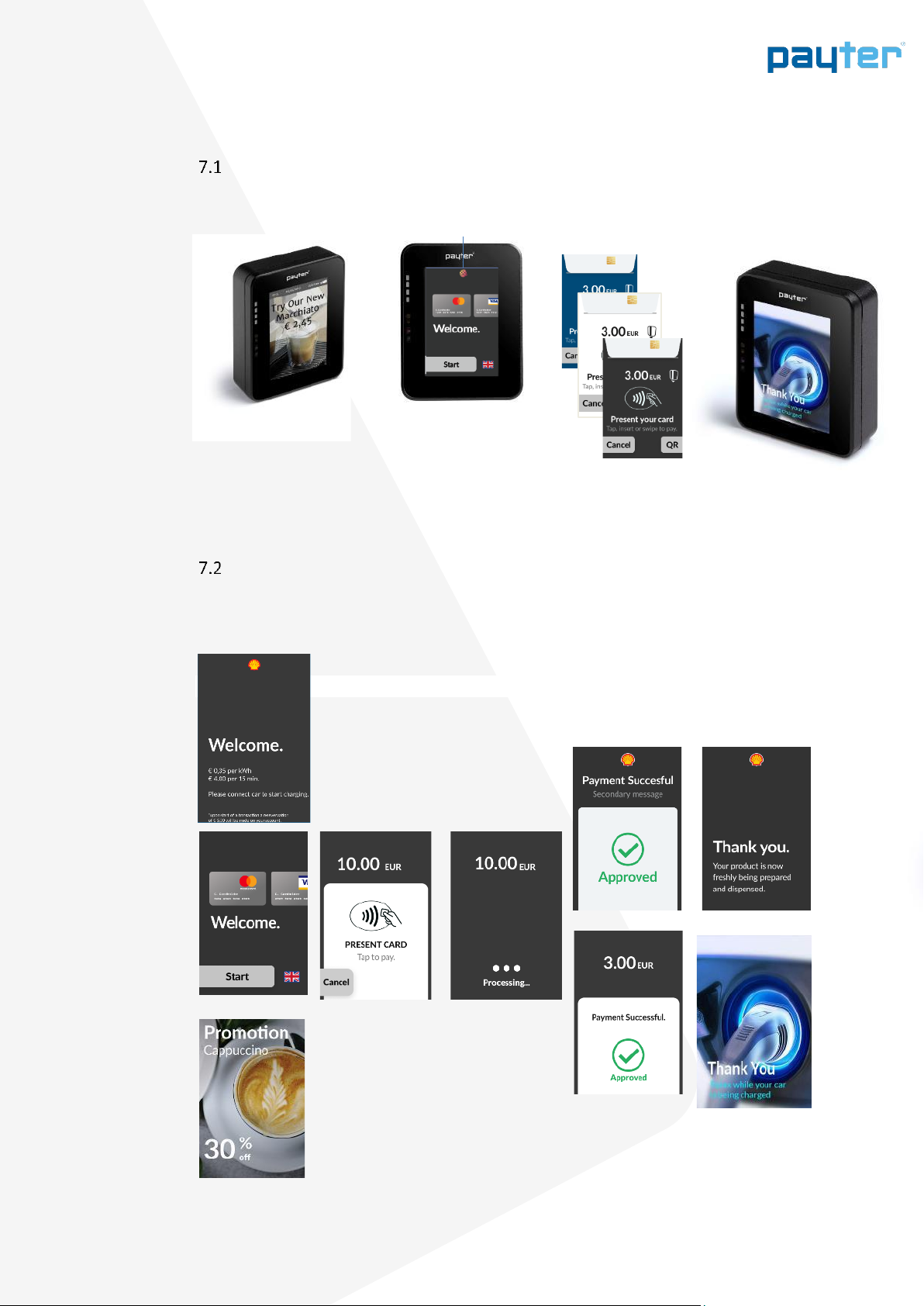
7. User Interface
Customisation
The following parts of the user Interface can be customized to reflect your company brand:
Example Payment flow
Idle screens Scanning for card Authorising Transaction Thank message
Rotating Result
Customised
Small Logo in display Background colour Thank you message
Idle screens prior to the start of
transaction, i.e. with product
placement

User Manual
V1.3 - 202301
Page 19 of 43
8. Configuration
The Apollo terminals are continuous connected to the Payter Terminal Management System
(TMS). The configuration of the terminals, including Key loading can only be done through the
MyPayter TMS portal.
The MyPayter portal allows:
•Efficient and timely deployment of keys, configuration updates and payment device
firmware
•Remote management of large quantities of Payter Terminals
•Future proof system in which changes in functionality can be applied easily, safely, and
quickly, while reducing the Cost of Ownership.
•Continued EMV compliance
The MyPayter Portal provides detailed insight
into your transactions and the ability to create
customized reports. Thanks to the real-time
connection with the terminals, you’ll have an
instant overview of which terminals are on-line.
Access
You will receive an email invitation to set a
password for your account. The ‘Set Password’
button will lead you to our Reset password site.
We have generated a unique secure code for
you, in case the code is not automatically
populated, please copy this code from the
invitation email.

User Manual
V1.3 - 202301
Page 20 of 43
9. Mechanical Integration
Front mounting
The Apollo series terminals can be directly mounted on the front panel of a machine.
The mounting footprint of Figure 5 is applicable for both the Apollo and the ApolloMax terminal.
Make sure that there is an opening in your machine large enough to accommodate
the placement of the MDB/power cable and antenna cable or the LAN cable
indicated by the orange rectangular in below figure.
Figure 5: Mounting footprint with dimensions in millimeters (left) and side view (right)
This manual suits for next models
1
Table of contents
Other Payter Payment Terminal manuals


