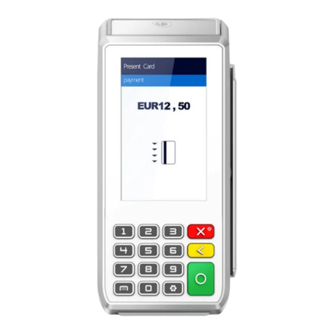
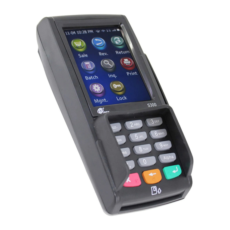
Payter P6 Series User manual

Copyright © 2010 Payter..
All rights reserved. No part of this document may be reproduced in any form by print, photo print, microfilm, electronic copy or any other
means without written permission by Payter BV.
P6X User Manual
Document version : 3.0
Document status : Release
Date : 30-01-2017
Document ID : PTR-40-10-ML-C-0003-03
NOTICE
This manual contains intellectual property, including but not limited, to trade
secrets and know-how, operating procedure and production procedures that
belong solely to Payter B.V.
Disclosure and/or use and/or reproduction of any part of this document strictly
forbidden, except under a written license from Payter B.V.
Payter B.V.
Rozenlaan 115
3051 LP Rotterdam
The Netherlands
P6X User Manual

P6X Series User Manual
Page 2 / 50
Copyright © 2014 PAYTER
BV. All rights reserved. No
part of this document may be
reproduced in any form by
print, photo print, microfilm,
electronic copy or any other
means without written
permission by Payter BV.
Revision History
Rev
Change
Author
0.1
Concept version
Payter
0.2
Added Vend Settings Tool items
Payter
1.0
Comments and minor modifications, R1
Payter
2.0
Updated Vending setting screenshots, minor
corrections
Payter
3.0
Added P66, P66S models
Payter

P6X Series User Manual
Page 3 / 50
Copyright © 2014 PAYTER
BV. All rights reserved. No
part of this document may be
reproduced in any form by
print, photo print, microfilm,
electronic copy or any other
means without written
permission by Payter BV.
Abbreviation list
Abbreviation
Description
3G
Third Generation (mobile communication system)
CCI
Coffee Credit Interface
DC
Direct Current
DHCP
Dynamic Host Control Protocol
DNS
Domain Name Server
EDGE
Enhanced Data for GSM (Global System for Mobile communication) Evolution
EMV
Europay Mastercard Visa
EVA
European Vending Association
GPRS
General Packet Radio Service (mobile communication system)
HSPA
High Speed Packet Access (mobile communication system)
IP
Internet Protocol
LAN
Local Area Network
MDB
Multidrop Bus, Communications bus standard for Vending Machines
ms
Miliseconds
PSP
Payment Service Provider
PVP
Payter Vending Protocol
RTP
Remote Terminal Protocol
SAM
Secure Authentication module
SDK
Software Development Kit
SIM
Subscriber Identification Module
USB
Universal Serial Bus
VMC
Vending Machine Controller

P6X Series User Manual
Page 4 / 50
Copyright © 2014 PAYTER
BV. All rights reserved. No
part of this document may be
reproduced in any form by
print, photo print, microfilm,
electronic copy or any other
means without written
permission by Payter BV.
Table of Contents
Revision History .............................................................................................. 1
1. Introduction........................................................................................... 6
2. Document Scope.................................................................................... 6
3. P6X Terminal Overview .......................................................................... 7
P68 3in1 terminal ............................................................................................................. 7
P66 Contactless Only Terminal ......................................................................................... 8
P66 Split Build on Top terminal ........................................................................................ 9
Rear view ........................................................................................................................ 10
4. Basic Connectivity Features.................................................................. 11
Host Machine Interface .................................................................................................. 12
Internet Connection........................................................................................................ 12
Terminal Configuration................................................................................................... 13
5. Payment Flow ...................................................................................... 14
Description...................................................................................................................... 14
Accepted Card types ....................................................................................................... 14
Transaction & Display messaging ................................................................................... 15
6. Modes of Operation............................................................................. 17
MDB mode...................................................................................................................... 17
6.1.1 Description.............................................................................................................. 17
6.1.2 Connecting the terminal ......................................................................................... 17
6.1.3 Pay flow .................................................................................................................. 18
6.1.4 Applicable Settings ................................................................................................. 18
Executive Mode .............................................................................................................. 19
6.2.1 PROTOCOL A (EXECUTIVE) ...................................................................................... 19
6.2.2 Vendbox.................................................................................................................. 19
6.2.3 Applicable settings.................................................................................................. 19
Potential Free Pulse Contact (Autoscan mode) .............................................................. 20
6.3.1 Description.............................................................................................................. 20
6.3.2 Connecting the terminal ......................................................................................... 20
6.3.3 Pay flow .................................................................................................................. 20
6.3.4 Applicable Settings ................................................................................................. 20
RTP Mode ....................................................................................................................... 22
6.4.1 Description.............................................................................................................. 22
6.4.2 Applicable Settings ................................................................................................. 22
CCI Mode ........................................................................................................................ 23
6.5.1 Description.............................................................................................................. 23
6.5.2 Connecting the Terminal ........................................................................................ 23
6.5.3 Pay flow .................................................................................................................. 23
6.5.4 Applicable Settings ................................................................................................. 23
PVP Mode ....................................................................................................................... 24
6.6.1 Description.............................................................................................................. 24
6.6.2 Connecting the Terminal ........................................................................................ 24
6.6.3 Applicable Settings ................................................................................................. 24
7. Setting Up Internet .............................................................................. 25
LAN connection............................................................................................................... 25
7.1.1 Applicable Settings ................................................................................................. 25
GPRS/EGDE/3G/HSPA MODEM ...................................................................................... 27
7.2.1 Connection Setup ................................................................................................... 27
7.2.2 Applicable Settings ................................................................................................. 28
8. Terminal Configuration ........................................................................ 29
Installing Vending Settings Tool...................................................................................... 29
Connecting to the terminal............................................................................................. 29
9. Dimensions & Mounting....................................................................... 30
Device opening ............................................................................................................... 30

P6X Series User Manual
Page 5 / 50
Copyright © 2014 PAYTER
BV. All rights reserved. No
part of this document may be
reproduced in any form by
print, photo print, microfilm,
electronic copy or any other
means without written
permission by Payter BV.
Mounting options ........................................................................................................... 31
1.1.1........................................................................................................................................ 31
Dimensions P68 The Arc ................................................................................................. 33
Dimensions P66 The Plane.............................................................................................. 34
Dimensions The Angle Casing ......................................................................................... 35
Installation P66 Split ....................................................................................................... 36
Dimensions P66S Split Unit............................................................................................. 37
1.1.2........................................................................................................................................ 37
10. Technical Specifications ....................................................................... 38
11. Troubleshooting................................................................................... 39
Result Codes ................................................................................................................... 39
LAN troubleshooting....................................................................................................... 41
Mobile Internet troubleshooting .................................................................................... 43
12. Warnings ............................................................................................. 44
AC Adapter...................................................................................................................... 44
Terminal.......................................................................................................................... 44
13. Contact ................................................................................................ 44
14. Installation Guide................................................................................. 45
15. FCC Compliance Statement (P68 only) .................................................. 47
16. CE Declaration of Conformity ............................................................... 48
17. Licenses ............................................................................................... 50
LWIP................................................................................................................................ 50
SPIFFS.............................................................................................................................. 50

P6X Series User Manual
Page 6 / 50
Copyright © 2014 PAYTER
BV. All rights reserved. No
part of this document may be
reproduced in any form by
print, photo print, microfilm,
electronic copy or any other
means without written
permission by Payter BV.
1. Introduction
Thank you for choosing a P6X Series Payment Terminal for your application.
These terminals are designed for use in unattended points of sale such as Food and Beverage
vending machines or parking ticket machines, that require no PIN.
With the objective of creating a cost efficient multifunctional payment terminal, a P6X Series
Terminal can support many payment schemes and a large variety of host applications.
The Terminal can be used as a drop-in replacement for your existing application using industry
standard interfaces such as Multi Drop Bus (MDB) or potential free pulse contact. Also available
are proprietary interface options (RTP, PVP), that uses either Ethernet, USB or RS232 to connect
the P6X terminal using a Payter proprietary protocol.
An internet connection, required for transaction processing, can be provided to the terminal by
connecting to a LAN network. If no LAN is available, an optional 3G/HSPA Modem can provide a
high-quality internet connection, ensuring your transaction processing performance will not
degrade because of a low internet speed.
The P6X Terminal series support reliable remote management functionality for firmware updates
and configuration changes. It is highly recommended that you always leave your terminal on and
connected to the internet, to ensure that your it can be managed properly.
2. Document Scope
This manual is intended for technicians or operators that want to familiarize him/herself with the
functionality of the P6X Terminal Series. The Terminals that are discussed in this document are
the P68 The Arc, and P66 The Plane. The two terminals have Quite similar functionality, and
where applicable the differences are explained in the relevant chapters.
It is also a good starting point for developers and integrators who intend to integrate the a P6X
terminal in their(vending)Machine, although additional documents would be required, and are
available upon request.

P6X Series User Manual
Page 7 / 50
Copyright © 2014 PAYTER
BV. All rights reserved. No
part of this document may be
reproduced in any form by
print, photo print, microfilm,
electronic copy or any other
means without written
permission by Payter BV.
3. P6X Terminal Overview
P68 3in1 terminal
Fig. 1 - Front view
Nr.
Item
Description
1
Led Indicators
Transaction status indication
2
Status Display
Blue Backlight
Shows transaction information and basic
device diagnostics.
3
Contactless Symbol
Location for tapping Contactless Cards
4
Contact Card Slot
Push/Pull type
5
Magnetic Stripe Card Swipe Slot
3 Track Reader
6
Triangle Button
Multifunction button
Buzzer
Indicates a successful/failed transaction
Table 1 –Front Item description
1
5
2
3
6
4

P6X Series User Manual
Page 8 / 50
Copyright © 2014 PAYTER
BV. All rights reserved. No
part of this document may be
reproduced in any form by
print, photo print, microfilm,
electronic copy or any other
means without written
permission by Payter BV.
P66 Contactless Only Terminal
Fig. 2 - Front view
Nr.
Item
Description
1
Led Indicators
Transaction status indication
2
Status Display
Blue Backlight
Shows transaction information and basic
device diagnostics.
3
Contactless Symbol
Location for tapping Contactless Cards
4
Triangle Button
Multifunction button
Buzzer
Indicates a successful/failed transaction
Table 2 –Front Item description
1
3
4
2

P6X Series User Manual
Page 9 / 50
Copyright © 2014 PAYTER
BV. All rights reserved. No
part of this document may be
reproduced in any form by
print, photo print, microfilm,
electronic copy or any other
means without written
permission by Payter BV.
P66 Split Build on Top terminal
The P66 Split is the ideal solution for machines which has minimum space to integrate a terminal
such as snack walls and toilets. P66S is identical to the P66 terminal with the exception that the
card reader and the communication is split into two parts. The card reader can be mounted on
top of any machine, while the communication unit is located inside the machine.
Vending Machine
Section View
Front (Reader) Unit
Ribbon Cable
Communication Unit

P6X Series User Manual
Page 10 / 50
Copyright © 2014 PAYTER
BV. All rights reserved. No
part of this document may be
reproduced in any form by
print, photo print, microfilm,
electronic copy or any other
means without written
permission by Payter BV.
Rear view
This Part of the casing is similar for P68 & P66
Fig. 3 –Rear View
Nr.
Item
Description
1
3G/HSPA Modem
The Modem is placed behind a hatch
labeled MODEM
2
Antenna Connector
(SMA-Female)
Connect a suitable 3G/HSPA BAND
antenna to this connector.
3
USB port
Host Machine Interface
4
RS232 Port
Host Machine Interface
5
MDB Port
Host Machine Interface
6
DC Input Port
Power Supply Adapter connection.
7
Ethernet Port
Host Machine Interface and/or Internet
connection.
8
SAM slots
The SAM slots are located behind a
Hatch labeled SAM MODULES.
9
Ribbon Cable connector
(Split units only)
To connect the Card Reader front unit in
the P66 Split configuration
Table 3 –Rear view item description
1
2
3
4
5
6
1
7
8
9

P6X Series User Manual
Page 11 / 50
Copyright © 2014 PAYTER
BV. All rights reserved. No
part of this document may be
reproduced in any form by
print, photo print, microfilm,
electronic copy or any other
means without written
permission by Payter BV.
4. Basic Connectivity Features
Host Machine Interface
The P6X terminal supports many interfaces available to connect to your
host machine. Chapter 4.1 gives an overview on the available machine
interfaces.
Internet Connection
Payment transactions that the terminal performs may require online
authorization. The terminal will connect with the Payment service
provider through an available internet connection. Chapter 4.2 gives an
overview on the available methods to connect to the internet.
Terminal Configuration
The P6X terminal requires a Configuration to function properly. This
configuration consists of multiple parts and is further detailed in chapter
4.3.
Table 4 –Basic Connectivity Features
Fig. 4 - Connectivity Diagram
Terminal
Configuration
LAN, 3G
Internet
Host Machine
Hardware
Remote Terminal
Management
Payment
Service
Provider
Host Machine
MDB
Ethernet
Pulse i/0
Etc.

P6X Series User Manual
Page 12 / 50
Copyright © 2014 PAYTER
BV. All rights reserved. No
part of this document may be
reproduced in any form by
print, photo print, microfilm,
electronic copy or any other
means without written
permission by Payter BV.
Host Machine Interface
The P6X terminal series support several different interfaces to connect to your host machine.
Choosing an interface will largely depend on the interface that is supported by your machine,
and the preferred method of powering the terminal. Table 1 gives a summary of available
options.
Interface
Mode
Description
MDB
The Multi Drop Bus is an industry standard interface for vending machines. If your
machine supports an MDB - Cashless Device, then this will require little effort to reach
a working solution, provided that the MDB standard is correctly implemented in your
machine. An advantage of MDB is that the interface also supplies power to the
terminal, requiring no additional power supply.
Executive
a P6X Terminal can be combined with the VendBox to enable “Executive Node”
functionality. The VendBox is sold separately from the terminal and acts as a
converter between Executive and MDB.
Potential
Free Pulse
Contact
A configurable potential free pulse contact is available to signal your application that
a payment transaction was successfully processed. In addition, an input port is
available to enable/disable the terminal, if for example the machine is out of order.
Although a Potential free pulse contact interface is widely used, there is no
standardization, and requires attention to electrical details before it can be used.
RTP
Remote Terminal Protocol, is used to control the terminal functionality from
anywhere on a LAN, or through USB, directly from your software application.
PVP
This message based protocol provides basic functionality for machine to payment
terminal communication, over an RS232 connection.
CCI
This message based protocol is used in certain coffee machines, and communicates
over RS232.
Table 5 –Available Host Machine interface modes.
Internet Connection
For most applications, involving a P6X terminal, a stable internet connection is required, the
available options described in table 2.
Interface Type
Description
Ethernet
a P6X Terminal can be connected to a LAN, through its onboard Ethernet port,
and connect to the Internet through the LAN.
3G/HSPA
modem
In case there is no access to a LAN network a 3G/HSPA MODEM is optionally
available
Table 6 –Available Internet connection
Refer to chapter 7 for more detailed information about configuring internet.

P6X Series User Manual
Page 13 / 50
Copyright © 2014 PAYTER
BV. All rights reserved. No
part of this document may be
reproduced in any form by
print, photo print, microfilm,
electronic copy or any other
means without written
permission by Payter BV.
Terminal Configuration
The Terminal configuration covers multiple aspects that need to be configured before a
successful transaction can be performed. Most of the settings are determined when a terminal is
ordered for a specific Payment host provider. Settings related to a terminal interface mode or
network communication are usually set correct by default, in some cases settings have to be
modified for the terminal to function properly.
Configuration
Description
Secure
Configuration Files
These files contain the settings that determine the certified terminal
configuration and cannot be modified without consulting the
manufacturer.
Terminal Settings
These settings need to be configured for each mode in which the
terminal is operating, to allow communication with the host Machine
and payment service provider. Each chapter gives an overview of the
related settings.
Optional SAM
The SAM module contains cryptographic key material that is needed to
set up a secure connection, and authenticate the terminal, with the
payment service provider.
Optional Data SIM
A 3G/HSPA MODEM option requires a data SIM with access to mobile
internet services. A SIM card can be provided by either your local
mobile internet provider or by Payter.
Table 7 –Terminal Configuration items

P6X Series User Manual
Page 14 / 50
Copyright © 2014 PAYTER
BV. All rights reserved. No
part of this document may be
reproduced in any form by
print, photo print, microfilm,
electronic copy or any other
means without written
permission by Payter BV.
5. Payment Flow
Description
A Host machine is always responsible for initiating a payment on the terminal, the only exception
is Auto Scan mode. This chapter describes how a payment is performed by a user, and how to
interpret the feedback that is given by the terminal. Some operational modes can introduce a
slight difference in this behavior, these details will be covered in chapter 6 for each respective
mode, if applicable.
Accepted Card types
The P68 terminal accepts one of these three card types, from any of the configured payment
schemes to perform a payment. The P66 terminal is a contactless payment only terminal and
therefore only accepts Contactless Cards and Mobile phones. The terminal can also accept
proprietary card types for example for loyalty applications, or a closed user group application.
Card Type
Description
Contactless Card/
Mobile phones
When prompted to do so, tap the Card or Phone with NFC
on the Contactless Symbol on the front of the terminal.
Keep the Card in place until the terminal indicates that the
card can be removed.
Contact Chip Card
Insert the Chip Card in the illuminated card slot. Do not
remove the card until you are prompted to do so.
Magnetic Stripe
Card
The user can swipe a magnetic stripe card through the
swipe slot as indicated on the P68 terminal.
Table 8 - Accepted card types
Fig. 5 –Accepted payment types

P6X Series User Manual
Page 15 / 50
Copyright © 2014 PAYTER
BV. All rights reserved. No
part of this document may be
reproduced in any form by
print, photo print, microfilm,
electronic copy or any other
means without written
permission by Payter BV.
Transaction & Display messaging
When the host machine initiates a transaction, the following display message will prompt user to
pay on the terminal:
Fig. 6 –Initiating transaction.
State
Display message
LED indicators
Buzzer sound
Initiating Transaction
“Your card please” + Amount
1
Contactless Card Presented
Cards Read OK
“Card read OK remove card”
1,2,3,4
Authorizing Transaction
“Authorizing remove card”
1,2,3,4
Transaction Approved
“You have paid”
Success tone
Transaction Declined
"Not accepted pay differently"
Error tone
Contact Chip Card Presented*1
Confirm Amount
"Press Start for OK”
Authorizing Transaction
“Processing please wait”
Transaction Approved
“You have paid Remove card”
Success tone
Transaction Declined
“Not accepted Remove card”
Error tone
Magnetic Stripe Card Presented*1
Authorizing Transaction
“Authorizing”
Transaction Approved
“You have paid”
Success tone
Transaction Declined
"Not accepted pay differently"
Error tone
Table 9 –Basic pay flow messages.
*1 P68 only functionality
Some messages may be presented differently for different payment service provider, but in
essence the pay flow is the same.

P6X Series User Manual
Page 16 / 50
Copyright © 2014 PAYTER
BV. All rights reserved. No
part of this document may be
reproduced in any form by
print, photo print, microfilm,
electronic copy or any other
means without written
permission by Payter BV.
Display message
Description
Possible Solution
"Try another card"
Unable to read (contactless) card /
contactless card not supported.
Try to present card again. If
persistent, try a different card.
"You have waited too long"
The transaction initiation timed out
Retry Transaction
“Transaction canceled”
Transaction was canceled by the
User
"One card only"
Two contactless cards were detected
by the terminal simultaneously
"Chip cannot be read"
Unable to read contact card /contact
card not supported
Check if contact card is inserted
properly.
"Try other interface"
The transaction cannot be
Initiated using the current interface.
Use another card interface, for
example try contact interface
instead of contactless.
“Service Code nnn”
A processing error occurred; the
specific error code “nnn” provides
details about the error.
Refer to chapter 11.1 for error
code details
Table 10 –Additional messages
Error messages
If during the transaction a fault occurs that is not indicated by one of the previous messages a
result code may be returned. Refer to chapter 11.1 for the meaning of the result code.

P6X Series User Manual
Page 17 / 50
Copyright © 2014 PAYTER
BV. All rights reserved. No
part of this document may be
reproduced in any form by
print, photo print, microfilm,
electronic copy or any other
means without written
permission by Payter BV.
6. Modes of Operation
MDB mode
6.1.1 Description
The majority of the Vending Machines support the MDB or Executive communication protocol.
MultiDrop Bus (MDB)
“The multidrop bus used by vending machine controllers to communicate with the vending
machine's components, such as a currency detector, is also called MDB. In use since the 1980s, it
is now an open standard of the National Automatic Merchandising Association, or NAMA.”
In general:
The Payter Vending terminals will support all Vending Machines that comply with the MDB
specifications. Level 1-3.
This mode of operation is commonly used for vending machines.
The vending machine controller(VMC) and the terminal are physically connected using a single
cable for power and communication. The VMC is the BUS master and instructs the terminal when
to initiate a transaction.
All electrical and datalink aspects are covered by the MDB standard, this simplifies the
integration of the terminal to a plug and play experience. With only a few settings that require
attention. The terminal is classified as an MDB Cashless Device, and supports Level 3
functionality including “always idle mode” from the MDB specification v4.2.
For a detailed description on the MDB interface, consult the MDB v4.2 specification
documentation.
6.1.2 Connecting the terminal
Note: Always Turn off the vending machine when installing a new MDB device!
Connect the P6X terminal to the VMC using the supplied MDB Cable. Power up the vending
machine, the terminal should power up as well. After boot-up has completed the terminal should
automatically register with the VMC.
Fig. 7 –P6X Terminal VMC connection.
Vending Machine Controller
(VMC)
MDB Cable

P6X Series User Manual
Page 18 / 50
Copyright © 2014 PAYTER
BV. All rights reserved. No
part of this document may be
reproduced in any form by
print, photo print, microfilm,
electronic copy or any other
means without written
permission by Payter BV.
6.1.3 Pay flow
Depending on the type of vending machine, there are two possible ways to initiate a vend cycle.
If the vending machine supports MDB feature level 3 “always idle mode”, the user can initiate a
vend cycle by selecting a product. When “always idle mode” is not supported the vend cycle can
be initiated by pressing the “Start Button” on the terminal, and then selecting a product.
After product selection the user will be prompted to pay as described in chapter 5.
After a successful payment, the product will be dispensed. With most machines, the payment is
canceled if the vend is unsuccessful, but support for this depends on the features of the vending
machine. Contact your vending machine supplier for details.
6.1.4 Applicable Settings
The following behavioral settings require attention in MDB mode:
Fig. 8 –MDB settings
Setting
Description
MDB Level
[1,3] determines the capability level reported to the vending
machine. Should be left at 3 unless the terminal and vending
machine do not register correctly.
Session Timeout
Indicates the time period, in ms, for selecting a product after
the START button is pressed.
Note this is only applicable when not in “always idle” mode.
Session Amount
The amount, in cents, that the Terminal provides as Credit to
the vending machine at the start of a session.
Note this is only applicable when not in “always idle” mode.
Table 11 - MDB settings

P6X Series User Manual
Page 19 / 50
Copyright © 2014 PAYTER
BV. All rights reserved. No
part of this document may be
reproduced in any form by
print, photo print, microfilm,
electronic copy or any other
means without written
permission by Payter BV.
Executive Mode
6.2.1 PROTOCOL A (EXECUTIVE)
“Also known as Executive, this protocol was developed by Mars Electronics International in the
early 1980's to interface peripherals to electronically controlled vending machines. The definitive
Protocol A specification is produced by Mars Electronics International.”
Support for the MDB comes standard with the Payter terminal in case the Vending Machine only
supports the Executive protocol an additional converter (Payter VendBox) is required which can
be placed in between the terminal and the Vending Machine.
Vending Machine VendBox P6X Terminal
Fig. 9 –Executive Protocol functionality
6.2.2 Vendbox
The Vendbox acts as a bridge between the Executive vending protocol, and the MDB protocol,
and is designed to be used in combination with a Payter contactless terminal. When connected
to an Executive vending machine, the Vendbox acts as the Executive Master and delegate
commands to the Vending Machine Controller (VMC). It will also act as MDB VMC and send vend
requests to the MDB cashless device connected to the MDB bus.
For detailed specifications and installation instructions, please refer to the Vendbox manual.
6.2.3 Applicable settings
The terminal will be configured as a regular MDB device, see previous chapter.
MDB
(Cable provided with terminal; Not
included in the Vendbox)
Executive Connection
Power

P6X Series User Manual
Page 20 / 50
Copyright © 2014 PAYTER
BV. All rights reserved. No
part of this document may be
reproduced in any form by
print, photo print, microfilm,
electronic copy or any other
means without written
permission by Payter BV.
Potential Free Pulse Contact (Autoscan mode)
6.3.1 Description
Connecting a P6X Terminal to existing, coin mechanism only, applications can be challenging. To
be able to integrate a P6X Terminal in these existing applications, a potential free pulse contact
was added to the terminal features. Allowing the terminal to replace the coin mechanism or be
used in parallel.
A potential free pulse contact can signal a host machine that a payment was performed
successfully, the concept is similar to a pulse output on a coin mechanism interface.
In addition, a P6X terminal has an inhibit input that can be used to enable/disable payments on
the terminal, for example when the Host machine is out of order.
6.3.2 Connecting the terminal
Implementing this mode of operation requires attention to electrical details to which this
interface is bound. The pulse output is highly configurable in polarity, pulse width, pulses per
transaction etc. For a detailed description of the potential free pulse contact features, please
inquire with your local supplier about “Pulse I/O” documentation. This documentation describes
the electrical properties and the settings that are important for integration with your device.
6.3.3 Pay flow
When the terminal is powered up, it will automatically start scanning for cards. Every time a card
is presented, a transaction is performed for the indicated amount, and a pulse is given for each
successful transaction. It is the responsibility of the host machine to capture all the pulses that
are send by the terminal. When the host machine is not able to capture pulses or provide the
service for which is to be paid, the terminal should be disabled. By either powering down the
terminal or through enabling the terminal inhibit input. When the host machine functionality is
restored the terminal can be enabled again to resume operation.
6.3.4 Applicable Settings
The following settings control the behavior of the Autoscan Pulse Contact mode.
Fig. 10 –Autoscan Pulse settings
This manual suits for next models
3
Table of contents
Other Payter Payment Terminal manuals


