PCB Load & Torque, Inc. Toll-Free in USA 866-684-7107 716-684-0001 www.pcbloadtorque.com
S-TYPE LOAD CELL OPERATION MANUAL
4
6.1.2 Hysteresis
The difference between the ascending and descending
measured readings at 40% of full scale is used to calculate the
hysteresis value.
6.1.3 Best Fit Output
The best fit calibration second-order equation has been
calculated from the calibration data by the method of least
squares. Deviation between measured output and best-fit
output is calculated and displayed in the column next to the
best-fit output for each measurement increment. The
deviations (% Full Scale) of measured outputs from the
calculated best fit are tabulated for each measured reading.
6.1.4 Strain Gage Measurements
6.1.5 Shunt Calibration Standard Resistor
All S-type load cell calibrations use a 60K Ohm (0.1%)
precision resistor shunt calibration value that is supplied into
the calibration report.
6.1.6 Static Error Band (SEB)
The static error band (SEB) is determined by the maximum
deviations of the ascending and descending calibration points
from the best fit straight line through zero output. The SEB
includes the effects of nonlinearity, hysteresis, and non-return
to minimum load.
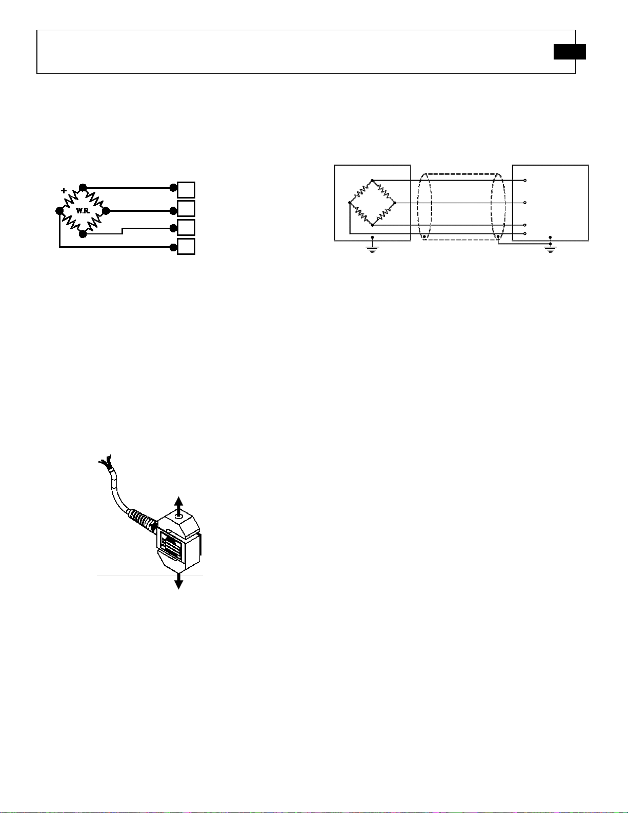
7.0 SHUNT CALIBRATION DESCRIPTION
Shunt calibration is used to simulate a known tension or
compression load on a load cell. The calibration certificate
will indicate which leg of the bridge to apply the shunt resistor
to for both tension and compression load simulation. Typically
tension is simulated by inserting the shunt resistor between the
+P and +S connector leads. Compression loading is simulated
by inserting the shunt resistor between the +S and –P
connector leads.
7.1 Resistor Value
S-type load cells have a nominal 2.0 mV/V full scale output.
For a 350 ohm strain gage bridge the precision shunt resistor
is, 60,000 ohms ±0.1%, simulates an output of approximately
73% of the full scale output for the load cell. The calibration
values for each bridge are found on the calibration certificates
supplied with each load cell.
7.2 Shunt Calibration Process
To perform the shunt calibration, use the following procedure:
1. Stabilize all forces on the load cell. If possible,
remove all loads.
2. Allow the powered sensor and signal conditioner to
warm up for a minimum of 30 minutes
3. Set the load indicator display to read exactly 00.000.
4. Connect the shunt resistor to the terminals specified
in the calibration certificate, and adjust the span or
gain until the display reads the force value stated on
the certificate.
5. Repeat steps 1-3 to verify that a valid calibration
setting has been obtained.
6. If possible, apply a known load to the measurement
system to further verify that the calibration has been
accurately set up.
7.3 Estimating Shunt Resistor for a Given Load
The following formula can be used to estimate the
approximate value of shunt resistor required to simulate a
mechanical load.
R
cal
= (250* R
b
) / (Output
FS
* L
cal
)
Where: R
cal
= Shunt Resistor (K ohms)
R
b
= Bridge Resistance (ohms)
Output
FS
= Full Scale output of the load cell (mV/V)
L
cal
= Load to be simulated, % of Load Cell Capacity
8.0 MAINTENANCE
Routine maintenance of the S-type load cell should include
cleaning the electrical connectors, housings, and mounting
surfaces with solutions and techniques that will not harm the
physical material of construction. Make sure liquids are not
allowed to migrate into devices that are not hermetically
sealed. Such devices should only be wiped with a damp cloth,
and never be submerged or have liquids poured on them.
Never use a pressure washer on the load cells.
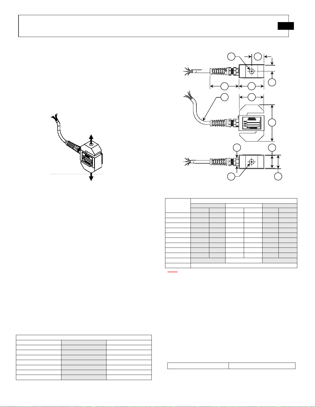
Bridge Resistance: 350 Ohm Nominal
Excitation: +P(A) to –P(D) Ohms
Signals: +S(B) to –S(C) Ohms
Leakage to Ground: > 5k GOhm
Bridge Unbalance: ±1.0% Full Scale
Output: 2.0 mV/V Nominal
Maximum Voltage: 20 VDC
Table 5 – Strain Gage Measurements