Kidde EG4 Series Assembly instructions

© 2020 Carrier 1 / 4 P/N 3102554-EN • REV 002 • ISS 31AUG20
Genesis LED EG4 Series Wall
Notification Appliance Installation
Sheet
Description
Genesis LED EG4A horns, EG4V strobes, and EG4VA horn-strobes
are wall-mounted plug-in fire alarm notification appliances designed for
indoor dry applications. See Table 1 to Table 3 for a list of models.
Table 1: EG4A horn models
Catalog number
Description
EG4
ARF Wall horn, red, FIRE
EG4
ARN Wall horn, red, no marking
EG4
AWF Wall horn, white, FIRE
EG4
AWN Wall horn, white, no marking
Table 2: EG4V strobe models
Catalog number
Description
E
G4VRF Wall strobe, red, FIRE
E
G4VRN Wall strobe, red, no marking
E
G4VWF Wall strobe, white, FIRE
E
G4VWN Wall strobe, white, no marking
Table 3: EG4AV horn-strobe models
Catalog number
Description
E
G4AVRF Wall horn-strobe, red, FIRE
E
G4AVRN Wall horn-strobe, red, no marking
E
G4AVWF Wall horn-strobe, white, FIRE
E
G4AVWN Wall horn-strobe, white, no marking
Genesis LED EG4 Series notification appliances feature:
• Field-configurable horn and strobe outputs. See Figure 2.
• Enhanced synchronization circuitry to comply with the latest
requirements of UL 1638 and CAN/ULC-S526.
• Input wiring test points on the front of the appliance when the
cover is removed.
Note: Synchronized operation requires a separately installed
synchronization device. See the control unit or power supply
compatibility list for compatible synchronization devices.
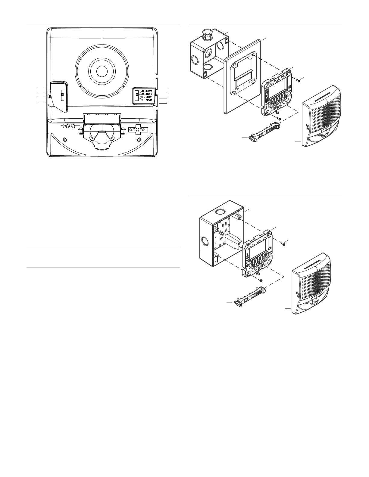
Configuration
Caution: Equipment damage hazard. Using excessive force when
removing the appliance cover may damage the cover and prevent it
from latching in place.
To configure the notification appliance:
1. Remove the appliance cover. See Figure 1.
Insert a small, flat-bladed screwdriver into the slot at the bottom of
the appliance.
Gently pull up on the screwdriver to pry the bottom of the
appliance cover down and away from the appliance.
Lift the bottom of the cover out and over the top of the appliance.
2. On horns and horn-strobes, set the sound output switch for the
required value. See Figure 2.
3. On strobes and horn-strobes, set the light output for the required
value. See Figure 2.
4. Replace the appliance cover.
Figure 1: Removing and replacing the cover
2 / 4 P/N 3102554-EN • REV 002 • ISS 31AUG20
Figure 2: Light and sound output settings
(1) Constant, low dB
(
2) Constant, high dB
(
3) T3 temporal, low dB
(4) T3 temporal, high dB
(5) 110 candela
(
6) 75 candela
(
7) 30 candela
(8) 15 candela
Note: Temporal 3 coding is the required output for fire notification
devices per NFPA 72. Any device coding other than Temporal 3 is at
the discretion and approval of the local authority having jurisdiction
(AHJ).
Installation
Install and wire this device in accordance with applicable national and
local codes, ordinances, and regulations.
Caution: Electrical supervision requires that you break the wire run at
each terminal. Do not loop the notification circuit field wires around the
terminals.
To install the appliance:
1. Using the screws supplied with the wiring plate, attach the wiring
plate and, if used, the trim plate to the electrical box. See Figure 3
and Figure 4. Do not overtighten the screws.
The trim plate is ordered separately.
2. Connect the field wiring. Observe signal polarity for the appliance
to operate properly. See Figure 4.
3. Remove the shorting clip (Figure 3, item 6). Retain for future use.
4. Plug the appliance into the wiring plate by setting the appliance on
the top of the wiring plate, and then snapping the bottom into
place. See Figure 5.
To unplug the appliance, press the spring clip on the bottom, and
then lift the appliance away from the wiring plate.
5. Test the unit for proper operation.
Figure 3: Typical electrical box mounting
(1) Electrical box
(2) Trim plate (optional)
(3) Wiring plate (required)
(4) Machine screw (2X, supplied with wiring plate)
(5) Notification appliance
(6) Shorting clip
Figure 4: Typical surface box mounting
(1) Surface box
(2) Wiring plate (required)
(3) Plastite screw (2X, supplied with surface mount box)
(4) Notification appliance
(5) Shorting clip
(1)
(2)
(3)
(4)
(5)
(6)
(7)
(8)
(3)
(4)
(2)
(1)
(5)
(6)
(1)
(2)
(3)
(5)
(4)
P/N 3102554-EN • REV 002 • ISS 31AUG20 3 / 4
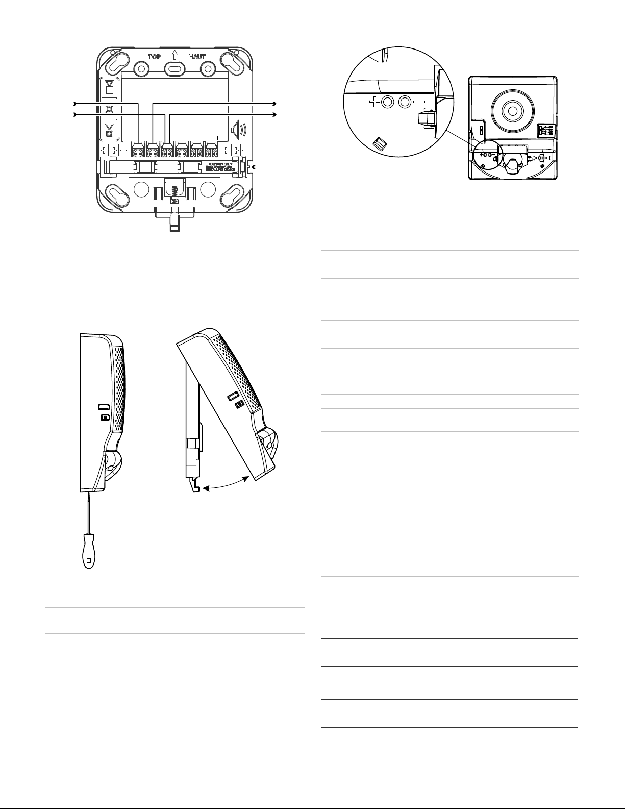
Figure 5: Wiring
(1) Horn/strobe circuit in (signal polarity shown in the active condition)
(2) Horn/strobe circuit out
(3) Shorting clip
Note: To maintain circuit continuity, do not remove the shorting clip
(Figure 4, item 3) until you are ready to install the notification
appliance.
Figure 6: Removing and replacing the appliance
Maintenance and testing
Caution: Equipment damage hazard. To maintain the required agency
listings, do not change factory-applied finishes.
This unit is not serviceable or repairable. If the unit fails to operate,
contact the supplier for a replacement.
Perform a visual and operational inspection in accordance with
applicable codes and standards or as directed by the local authority
having jurisdiction.
Input wiring test points are available on the front of the appliance when
the cover is removed. The test points let you easily spot check the field
circuit wiring without the need to remove the appliance from the wall.
See Figure 6.
Figure 7: Test points
Note: Marking indicates signal polarity when the circuit is active.
Specifications
Operating voltage
16 to 33 VDC, 16 to 33 VFWR
Operating current
See Table 4 to Table 6
Horn signal type
Constant or temporal (TC3)
Sound output
See Table 7
Sound pattern
See Table 8
Light output
15, 30, 75, or 110 cd
Strobe flash rate
1 fps (flash per second) approx.
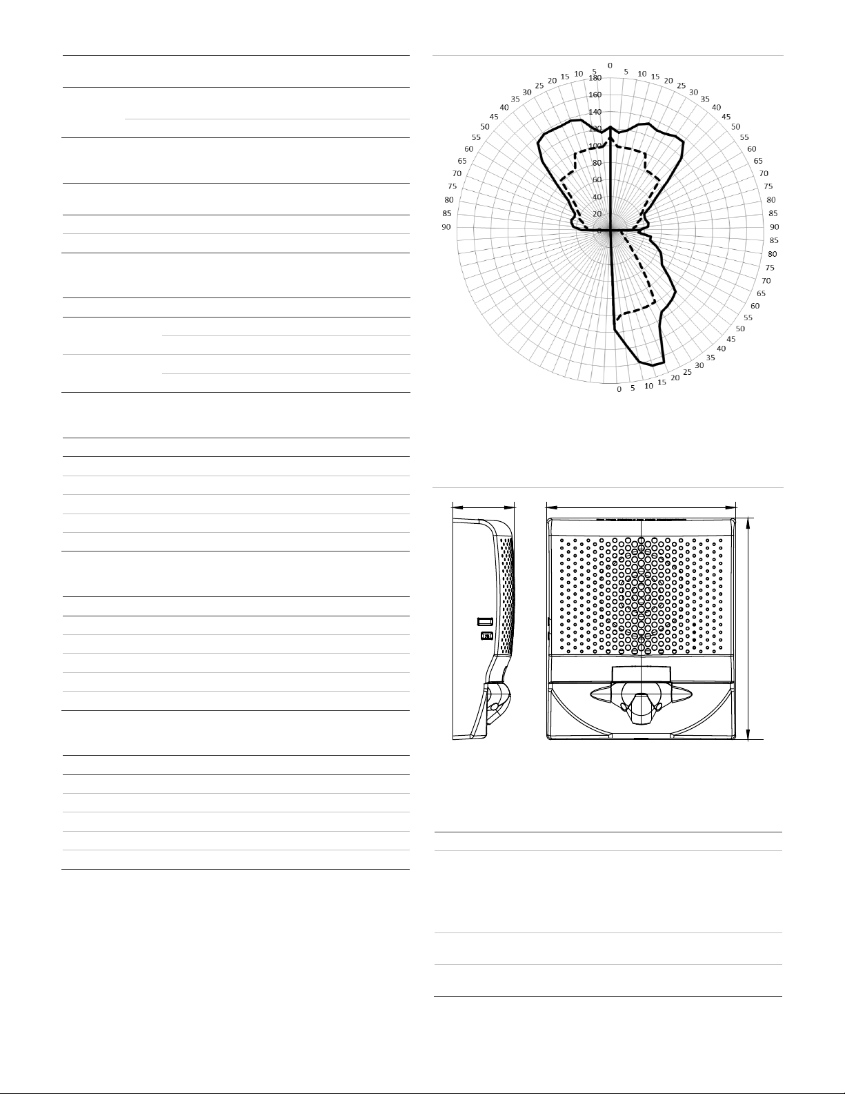
Light distribution
See Figure 7
Synchronization
20 Ω max. between any two devices.
To determine allowed wire resistance, refer to
these specifications, and the specifications
for the synchronized signal source.
Dimensions
See Figure 8
Strobe
-to-box center
offset
−1.70 in (−4.32 cm)
Compatible electrical
boxes
1-gang, 2-gang, 4-inch square, G4RSB,
G4WSB
Wiring plate
GRSW
Wire size
12 to 18 AWG (0.75 to 2.50 mm²)
Screw torque
Mounting screws
Terminal screws
10 lbf-in (1.2 N-m) max.
12 lbf-in (1.4 N-m) max.
Trim plate
s EG4TR, EG4TW
Replacement covers
See Table 9 to Table 11
Operating
environment
Temperature
Relative humidity
32 to 122°F (0 to 50°C)
0 to 93% noncondensing
Storage temperature
-40 to 158°F (-40 to 70°C)
Table 4: Operating current (horn models)
Sound setting
16 to 33 VDC
16 to 33 VFWR
C
-LOW, T-LOW 18 mA 22 mA
C
-HIGH, T-HIGH 28 mA 38 mA
Table 5: Operating current (strobe models)
Strobe setting
16 to 33 VDC
16 to 33 VFWR
15, 30, 75
, 110 28 mA 36 mA
(1) –
+(2)
(3)
–
+
N.C.
4 / 4 P/N 3102554-EN • REV 002 • ISS 31AUG20
Table 6: Operating current (horn-strobe models)
Strobe
setting
Sound setting
16 to 33 VDC
16 to 33 VFWR
15, 30, 75
,
110
C-LOW, T-LOW 40 mA 48 mA
C-HIGH, T-HIGH 50 mA 60 mA
Table 7: Sound output (horn and horn-strobe models)
Sound
setting Reverberant
(UL 464)
Anechoic
(CAN/ULC-S525)
C
-LOW, T-LOW 80 dBA 86 dBA
C
-HIGH, T-HIGH 86 dBA 92 dBA
Table 8: Sound pattern (ULC)
Axis
Angle Change in output
Horizontal
135° and 45°
–3 dBA
150° and 30° –6 dBA
Vertical
135° and 40° –3 dBA
150° and 30° –6 dBA
Table 9: EG4A horn replacement covers
Catalog number
Description
EG4
ARF-CVR Cover, wall horn, red, FIRE
EG4
ARN-CVR Cover, wall horn, red, no marking
EG4
AWA-CVR Cover, wall horn, white, ALERT
EG4
AWF-CVR Cover, wall horn, white, FIRE
EG4
AWN-CVR Cover, wall horn, white, no marking
Table 10: EG4V strobe replacement covers
Catalog number
Description
EG4
VRF-CVR Cover, wall strobe, red, FIRE
EG4
VRN-CVR Cover, wall strobe, red, no marking
EG4
VWA-CVR Cover, wall strobe, white, ALERT
EG4
VWF-CVR Cover, wall strobe, white, FIRE
EG4
VWN-CVR Cover, wall strobe, white, no marking
Table 11: EG4AV horn-strobe replacement covers
Catalog number
Description
EG4
AVRF-CVR Cover, wall horn-strobe, red, FIRE
EG4
AVRN-CVR Cover, wall horn-strobe, red, no marking
EG4
AVWA-CVR Cover, wall horn-strobe, white, ALERT
EG4
AVWF-CVR Cover, wall horn-strobe, white, FIRE
EG4
AVWN-CVR Cover, wall horn-strobe, white, no marking
Contact information
For contact information, see www.kidde-esfire.com.
Figure 8: 110 cd light distribution
(1) Horizontal left
(
2) Horizontal right
(3) Vertical bottom
──────── Measured
─
────UL minimum
Figure 9: Dimensions
(1) 1.62 in. (4.11 cm)
(2) 4.95 in. (12.57 cm)
(3) 5.78 in. (14.68 cm)
Regulatory information
UL rating
Regulated 24 DC and 24 FWR
FCC compliance
This device complies with part 15 of the FCC
Rules. Operation is subject to the following two
conditions: (1) This device may not
cause harmful
interference, and (2) this device must accept any
interference received, including interference that
may cause undesired operation.
Industry Canada
compliance
This Class A digital apparatus complies with
Canadian ICES-003.
Environmental
class
Indoor, dry
(1) (2)
(3)
(3)
(1) (2)
This manual suits for next models
4
Other Kidde Industrial Equipment manuals


