ABB Sace TMAX XT XT4 ELECTRONIC Installation instructions

—
INSTRUCTION HANDBOOK
1SDH002295A1001 - ECN000285442
TMAX XT XT4 THERMOMAGNETIC
Disassembly instructions


3
Disassembly instruction tmaX Xt Xt4 tHermomaGnetic
1. SCOPE
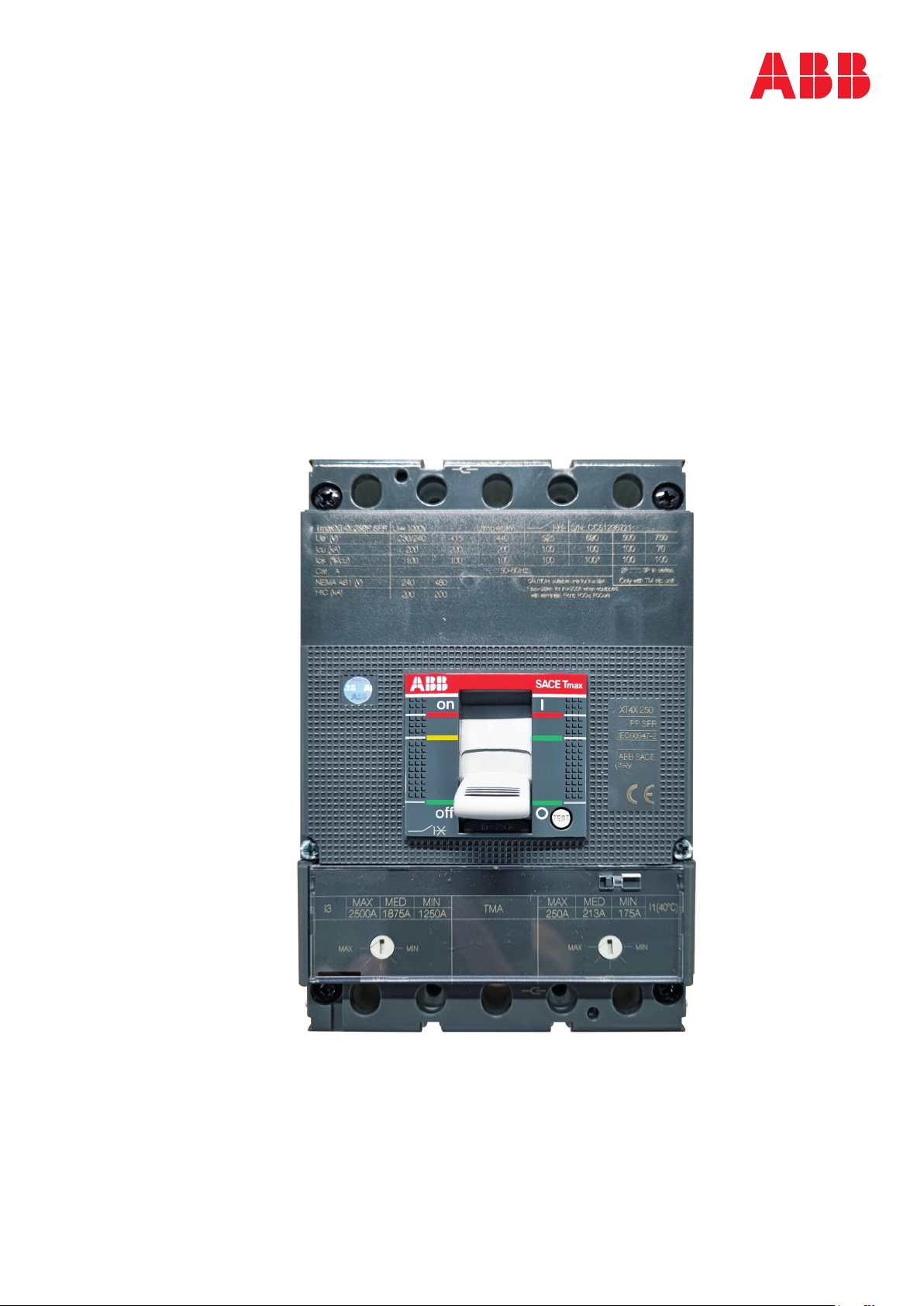
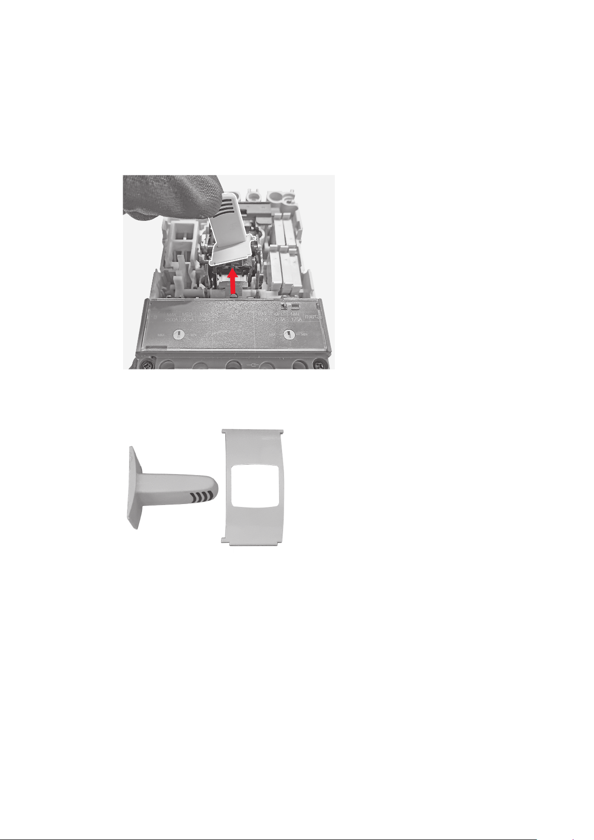
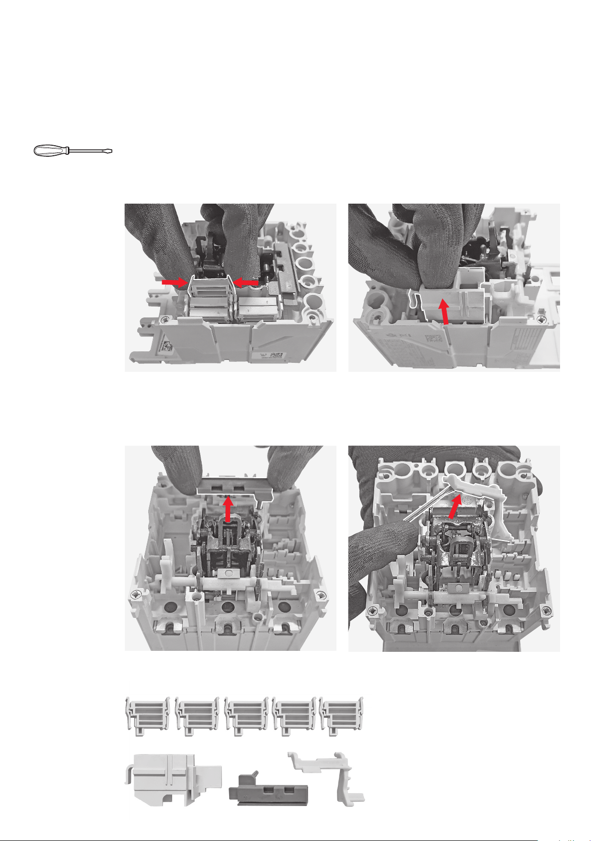
Scope of this document is to illustrate the step-by-step disassembly process of ABB SACE Tmax XT XT4
moulded case circuit breaker equipped with a thermomagnetic trip unit.
Document is focused on Tmax XT XT4 3p IEC version, anyway it allows to cover other versions of Tmax
XT XT4 circuit breaker equipped with a thermomagnetic trip unit with just few slight differences to be
taken into account.
Gloves Glasses Safety shoes Protective clothes
4. TOOLS
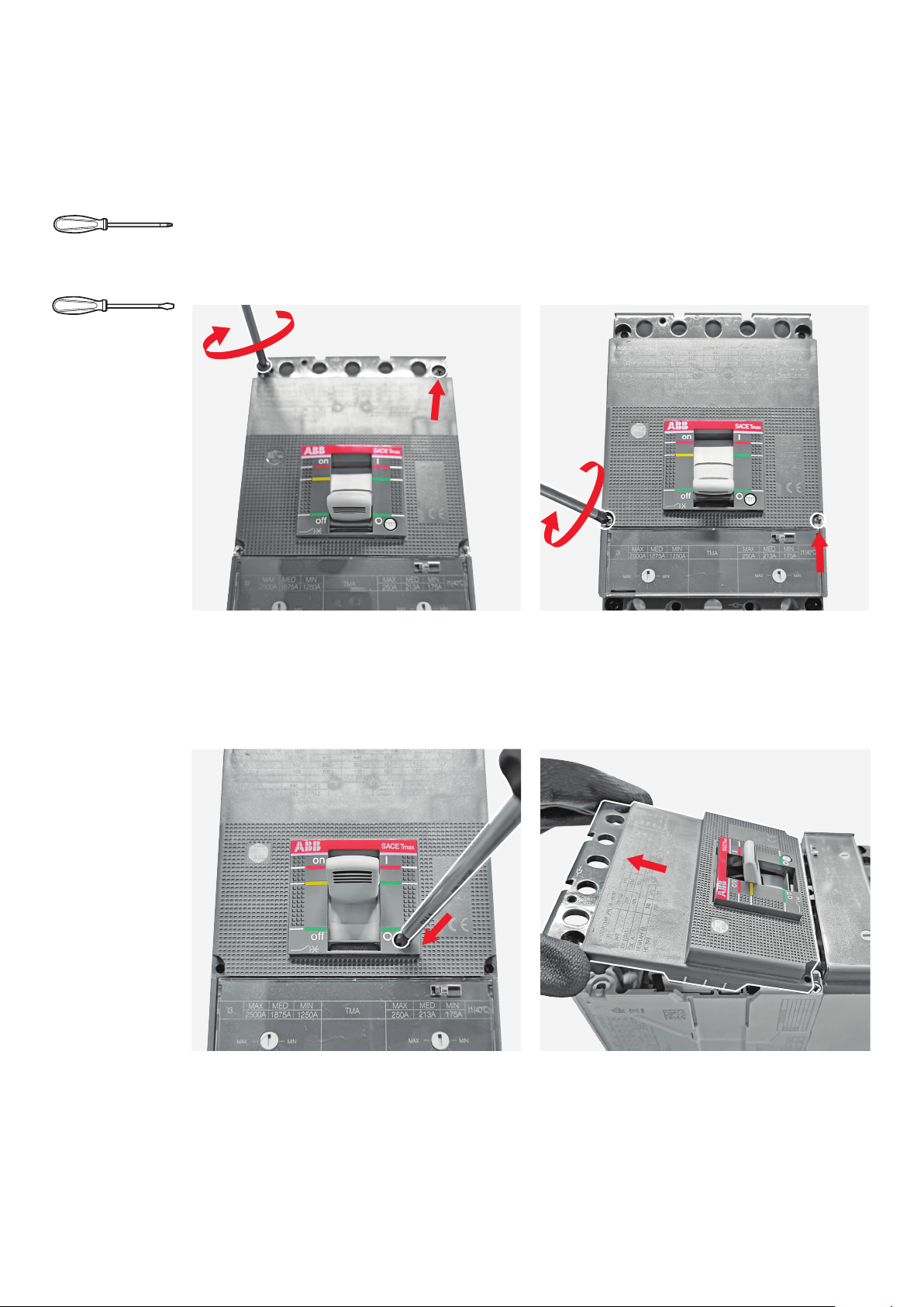
Disassembly operations require the use of tools (e.g. screwdriver, torx key, pliers, …); tools to be used
are specified inside each phase of the disassembly process (see Chapter 6).
3. PERSONAL PROTECTIVE EQUIMENT (PPE)
When performing disassembly, following safety Personal Protective Equipment (PPE) must be worn:
2. SAFETY NOTES
Before proceeding with any disassembly operation, it’s mandatory to put the circuit breaker in open
position.
Disassembly operations of circuit breakers must be performed by qualified and skilled personnel in
the electrical field (IEV 195-04-01: person with relevant education and experience to enable him or her
to perceive risks and to avoid hazards which electricity can create) and having a detailed knowledge of
circuit breakers.
Disassembly activites must be performed in an ergonomic workspace able to ensure protection of per-
sons demanded to perform disassembly activities.
Applicable national legislation and international standards in force at the time of disassembly of circuit
breakers must be taken into account in addition to prescriptions illustrated in this document.
ABB declines any responsibility for injury to people or damage to property resulting from a failure to
comply with the instructions set out in this document and with any applicable safety standard.

4
INSTRUCTION HANDBOOK
If disassembled parts require a separate treatment a specific indication is provided inside each phase
with reason why for the separate treatment (see Chapter 6).
Description Position inside circuit breaker Quantity
Cap kits In correspondence of circuit breaker connection terminals
Cases for microswitches In the right hole of the circuit breaker
Plug In the left hole of the circuit breaker
Rearming lever Mounted on the operating mechanism
Tripping shaft Mounted on the operating mechanism
Trip lever In the left hole of the circuit breaker
Open/close lever In the left hole of the circuit breaker
Case side protections Mounted on the breaking part
Trimmers Mounted on trip unit front
Magnetic shaft In the trip unit
6. DISASSEMBLY PROCESS
Circuit breakers disassembly process is constituted by a sequence of operations to be performed on
products after their dismounting from original installation. For each phase following information are
provided:
applicable)
5. SEPARATE TREATMENT
Table below lists parts requiring a separate treatment adding information about part location inside
circuit breakers and related quantity.

5
Disassembly instruction tmaX Xt Xt4 tHermomaGnetic
Tools
Allen key
Flat screwdriver
(Thermoplastics containing brominated flame retardants)
6.1 PHASE 1 – CAP KITS
1
By means of the allen key remove the screws
connected with the cap kits.
2
Insert the flat screwdriver as shown in Picture 2
and push it up in order to remove the cap kits.
Actions to be performed
Disassembled parts
6mm

6
INSTRUCTION HANDBOOK
Tools
Cross screwdriver
6.2 PHASE 2 – BREAKING PART FRONTAL
3
By means of the cross screwdriver unscrew
the 2 screws located in the upper part of the
breaking part frontal fixing the breaking part
frontal to the circuit breaker main structure.
5
By means of the cross screwdriver push the
trip test button.
6
Manually lift a little bit the breaking part
frontal and complete the removal pulling the
breaking part frontal as indicated by the arrow.
4
By means of the cross screwdriver unscrew
the 2 screws located in the lower part of the
breaking part frontal fixing the breaking part
frontal to the circuit breaker main structure*.
Actions to be performed
* Applicable to circuit breakers with V and X breaking
capacities only.
Flat screwdriverFlat screwdriver

7
Disassembly instruction tmaX Xt Xt4 tHermomaGnetic
7
By means of the flat screwdriver push up the
reset test rod and manually remove it.
Disassembled parts

8
INSTRUCTION HANDBOOK
6.3 PHASE 3 – TOGGLE AND ITS PROTECTION
8
Manually lift the toggle and its protection and
after separate the toggle from its protection.
Actions to be performed
Disassembled parts
Tools
–

9
Disassembly instruction tmaX Xt Xt4 tHermomaGnetic
6.4 PHASE 4 – TRIP UNIT
9
By means of the cross screwdriver unscrew the
2 screws fixing the trip unit frontal to the trip
unit main structure.
11
By means of the torx key unscrew the 3 screws
fixing the trip unit to the breaking part.
10
Manually disasseble the transparent protection
from the trip unit frontal.
12
Manually slightly pull the trip unit as indicated
by the arrow and after lift the trip unit in order
to complete the removal.
Actions to be performed
Tools
Cross screwdriver
Torx key
No. 15
Disassembled parts
*Trip unit will be furtherly disassembled (see Phases 6.11, 6.12 and 6.13)

10
INSTRUCTION HANDBOOK
6.5 PHASE 5 – PLASTIC PARTS MOUNTED ON THE BREAKING PART
13
Manually slightly push the 2 flaps present on
each case for microswitch located in the right
hole of the breaking part as indicated by the
arrows and after manually lift each case for
microswitch to complete the removal.
15
Manually lift cable crossing cover located in the
upper part of the breaking part.
14
By means of the flat screwdriver lift the plug
located in the left hole of the breaking part and
after manually complete the removal of the
plug.
16
By means of the flat screwdriver lift the white
plastic lever located in the upper part of the
breaking part and after manually complete the
removal of the white plastic lever.
Actions to be performed
Flat screwdriver
Disassembled parts
brominated flame retardants)
(Thermoplastics containing brominated flame
retardants)
Tools

11
Disassembly instruction tmaX Xt Xt4 tHermomaGnetic
6.6 PHASE 6 – REAR COVER
17
By means of the cross screwdriver unscrew the
2 screws fixing the rear cover to the breaking
part.
18
Manually remove the rear cover.
Actions to be performed
Disassembled parts
Cross screwdriver
Tools

12
INSTRUCTION HANDBOOK
Torx key
Tools
No. 20
Flat screwdriver
Pliers
6.7 PHASE 7 – OPERATING MECHANISM AND TRIPPING SHAFT
Actions to be performed
19
By means of the torx key (size 20) unscrew
the 4 screws located in the back part of the
breaking part.
20
By means of the flat screwdriver unhook the 2
springs mounted on the operating mechanism.
22
By means of the pliers remove the spring
mounted in the middle of the operating
mechanism.
21
Manually lift the operating mechanism and
remove it .

13
Disassembly instruction tmaX Xt Xt4 tHermomaGnetic
25
By means of the flat screwdriver and by means
of the pliers dismount the pin and remove the
pin and the 2 springs mounted on the pin.
23
Manually remove the tripping shaft from the
operating mechanism pulling it as indicated by
the arrow.
24
By means of the flat screwdriver remove the
metal plate mounted on the tripping shaft.
Disassembled parts
flame retardants)
(Thermoplastics containing brominated flame
retardants)

14
INSTRUCTION HANDBOOK
Tools
6.8 PHASE 8 – BREAKING PART COVER AND CONNECTED PARTS
Actions to be performed
Flat screwdriver
Pliers
Cross screwdriver
26
By means of the cross screwdriver unscrew the
2 screws located at the bottom corners of the
breaking part cover*.
28
Manually lift the breaking part cover.
27
By means of the cross screwdriver uncrew the
6 screws fixing the breaking part cover to the
breaking part base.
29
Manually lift the motor operator lever located
between the hole previously hosting the
operating mechanism and after complete
removal operation.
Torx key
No. 8
key must be used to unsrew the 2 screws.

15
Disassembly instruction tmaX Xt Xt4 tHermomaGnetic
30
By means of the pliers remove the hood
mounted on the motor operator lever removed
at previous step.
32
By means of the flat screwdriver remove the
3 plugs located in the bottom part of the
breaking part.
31
By means of the flat screwdriver slightly push
on the right the the trip lever mounted in the
bottom part of the breaking part and then lift
the lever in order to complete the removal.
33
By means of the cross screwdriver unscrew
the 3 screws located in the bottom part of
the breaking part; the terminals connections
between the breaking part and the trip unit
will fall from the breaking part by gravity.

16
INSTRUCTION HANDBOOK
34
Manually separate the plastic part from the
metals parts constituting the terminals
connections removed at previous step.
36
lever.
35
By means of the flat screwdriver remove the
metal plate from the plastic part constituting
terminals connections.
Disassembled parts
(Thermoplastics containing brominated flame
retardants)
(Thermoplastics containing brominated flame
retardants)

17
Disassembly instruction tmaX Xt Xt4 tHermomaGnetic
37
Manually remove the block lever.
39
By means of the pliers remove the 2 plugs
mounted on the moving contacts assembly*.
38
Manually lift the moving contacts assembly.
40
By means of the pliers remove the 2 plugs
mounted on the breaking part base.
6.9 PHASE 9 – MOVING CONTACTS AND ARCHING CHAMBERS
Actions to be performed
Tools
Flat screwdriver
Pliers
* Applicable to circuit breakers with V and X breaking capacities
only.

18
INSTRUCTION HANDBOOK
41
By means of the flat screw driver lift the
arching chambers and after manually complete
the removal operation.
42
Manually separate the arching chambers from
their supports.
Disassembled parts
Note:
unique assembly and by means of a flat screwdriver plates can be removed from the arching
chamber case.

19
Disassembly instruction tmaX Xt Xt4 tHermomaGnetic
6.10 PHASE 10 – FIXED CONTACTS
Actions to be performed
Tools
Flat screwdriver
Cross screwdriver
43
By means of the cross screw driver unscrew
the 6 screws located in the back part of the
breaking part base*.
45
Manually separate the plastic part from the
metal part constituting the fixed contacts.
44
Manually push the fixed contacts as indicated
by the arrow.
46
By means of the flat screwdriver remove the
metal plate mounted on the the plastic part
constituting the fixed contacts.
Torx key
No. 20
* To unscrew the 3 bottom screws mounted on circuit breakers

20
INSTRUCTION HANDBOOK
47
By means of the flat screwdriver unscrew the
screw fixing the case side protection to the
breaking part base.
48
By means of the flat screwdriver complete the
removal of the case side protections.
Disassembled parts
* Applicable to circuit breakers with V and X breaking capacities
only.
* Applicable to circuit breakers with V and X breaking capacities
only.
flame retardants)
Other manuals for Sace TMAX XT XT4 ELECTRONIC
1
Table of contents
Other ABB Industrial Equipment manuals
Popular Industrial Equipment manuals by other brands

Victron energy
Victron energy Phoenix Multi Series installation manual

Rauch
Rauch AERO ISOBUS Complementary instructions

Siemens
Siemens HMS-S installation instructions

SKF
SKF TMHP 15/260 Instructions for use

Schaeffler
Schaeffler ProLink instruction manual

Bosch
Bosch Rexroth ActiveMover Assembly instructions

CommScope
CommScope HELIAX FiderFeed DFJ-4S112B Technical publication

Parkside
Parkside MAGNETIC TORCH STAND PBHM 16 A1 Operation and safety notes

CAB
CAB 3014 Assembly instructions

Trane
Trane AFDH installation instructions

Lumen Dynamics Group
Lumen Dynamics Group OmniCure LX400+ user guide

KTC
KTC GOD80E instruction manual