Max-Air Systems Max Electric ME C 004 Series Manual

Rev: 10/10/22
Website
Max-Air Technology, Inc. • 114 Resource Drive • Wentzville, MO 63385 • United States of America
Tel +1.636.272.4934 • Toll Free 888.842.9998 • Fax 636.272.4937 • www.maxairtech.com • [email protected]
1
File Name: Max-Air_IOM_ME_C004_LVHV_Mod_converted.pdf
ME C 004 Series LV/HV | MOD
Installation, Operation and Maintenance Instructions
Throughout the installation phases and operation of this equipment,
safety procedures take precedence over all other activities. As a minimum:
1. Read and follow all instructions in this IOM.
2. Risk of electric shock! All wiring must be in accordance with applicable local
codes, regulations and the NEC. Be aware that there may be hazardous voltages
present which can shock, burn, or possibly cause permanent injury or even death.
3. Before handling electrical connections, disconnect power feeds. There may
be multiple power feeds connected to this unit. Check all terminal connections
carefully when servicing the actuator.
4. This is a mechanical gear train system with high torque outputs. Connected
mechanical linkages can and will cause personal injury if the user encounters a
pinch-point during movement.
Safety First!
Handling & Storage:
1. This device is an electrically powered mechanical transmission
system. It is comprised of a DC motor, an asynchronous AC motor,
or a polyphase AC motor, logic control PC boards, various discrete
electronic components and electrical storage devices, all of which
are susceptible to damage from high humidity. For this reason, this
device must be protected from direct contact with water and/or high
humidity storage environments.
2. Protect the device from physical damage while awaiting the
completion of installation processes.
3. If this product is installed in water valve systems and remains
unpowered during construction phases, condensate will accumulate
and possibly damage the product. This product MUST be powered up
at all times once it is installed in active piping systems.
Installation:
1. Conrm correct voltage and control before wiring and powering up
this actuator.
2. This device has been permanently lubricated at time of assembly.
Maintain proper lubrication level by ensuring the actuator is mounted
with the top cover at or above horizontal. This device is NOT designed
to mount with the top cover below horizontal.
3. Use approved conduit entry components to protect the interior of
the unit from ingress of foreign materials (including water). Utilize drip
loops to prevent conduit condensate from accumulating and entering
the actuator throught the EMT port(s).
4. Refer to the dimensional diagram (pg 4) for proper clearance on
all sides as well as the top cover clearance requirements. Determine
proper access space for the manual override system.
5. When mounting this device to a valve or damper, ensure the mating
between the valve stem (or coupling) is NOT deeper than the socket
depth in the bottom of the actuator. Use the proper length and thread
bolts for mounting. (See dimensional diagram pg 4).
6. Ensure the actuator is concentrically mounted to the valve stem.
Non-concentricity causes premature actuator or valve-stem seal
failure, or actuator stalling due to high-torque during travel.
7. Use properly sized power supplies and wire gauge over distance to
prevent actuator failure from stalling and overheating.
8. Refer to the wiring diagram sheet (folded, inserted under the
actuator cover) for wiring connections. You can also scan the QR code
above and navigate to the Max-Air website to obtain a full-size wiring
diagram.
9. Do NOT parallel wire multiple on-o actuators to the same eld
control terminals. This WILL cause unexpected movement of the
actuator(s), overheating and premature failure.
10. After installation and testing, do NOT operate the actuator with any
covers removed.
11. It is recommended to operate the actuator for at least ten minutes
once per month, as a minimum.
12. The internal heater is to be used in ALL applications.
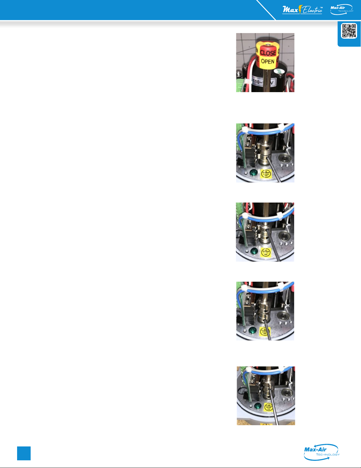
13. There are NO mechanical stops on this actuator. When using the
manual override on the bottom of the actuator, pay attention to the 3D
position indicator (Fig 1) on the top side to prevent overtravel outside the
intended travel range.
Caution! The entire top-works cam shaft, potentiometer drive
and position indicator on this model actuator rotates in the
OPPOSITE direction as the main output shaft at the bottom of the
actuator. The OUTPUT shaft of this actuator rotates CW to CLOSE
an attached valve. However the INDICATOR and shaft rotate CCW
to CLOSE. Follow the cam adjustment directions for this actuator
using THIS manual.

ME C 004 Series LV/HV | Mod
(con't) Installation, Operation and Maintenance Instructions
Rev: 10/10/22
Website
Max-Air Technology, Inc. • 114 Resource Drive • Wentzville, MO 63385 • United States of America
Tel +1.636.272.4934 • Toll Free 888.842.9998 • Fax 636.272.4937 • www.maxairtech.com • [email protected]
2
File Name: Max-Air_IOM_ME_C004_LVHV_Mod_converted.pdf
This actuator has been factory calibrated to operate between 0° and 90°.
Most quarter-turn products will not require recalibration of these settings.
Default Operating Mode:
This actuator leaves the factory with the following default settings:
Input signal is 4-20mA, response is direct acting (20mA = full CCW - OPEN), feedback is
4-20mA, Unit is set for 90° travel, and sensitivity is set at "3" (0.5% full scale).
This manual is written for proportional control actuators with DC or single phase AC
drive motors. (This may NOT the same as the power supply feeding the actuator).
This actuator must be calibrated prior to putting into service. If this is a stand-alone
actuator, follow all the steps given here after mounting the actuator to the driven device
(valve, damper or other). If this actuator has been factory mounted to the driven device,
more than likely it has already gone thru calibration and nothing further needs to be
done.
1. The bare actuator normally ships in the full CW (Closed) position. This can be veried
by observing the top-mounted 3D position indicator before the top cover is removed.
When in the full CW position, the color showing is RED and "CLOSE" is visible thru the
window. (Fig 1)
2.
Do NOT apply power at this time.
3.
Set the CW end of travel cam
.
a. Use the side-mounted 5mm hex manual override drive socket to drive the actuator
out to about 15~20 degrees open, then back to the desired CLOSED (CW) position. If
you have driven the device too far, you must drive back out to 15~20 degrees before
again approaching the correct CW stop. You cannot set the stop when driving in a CCW
direction due to cam dwell angle.
b. Using a 2.5mm hex key on CAM #2 (Fig 2), loosen the cam set screw and rotate the
cam CCW by pushing the hex key to the LEFT a few degrees. Lightly snug up on the set
screw until resistance is felt against the cam shaft. Pull the hex key to the RIGHT SLOWLY
until you hear a "click" from the associated (#2) cam switch and snug up on the cam
setscrew. Do not move the actuator. No need to overtighten the cam setscrew.
4.
Set the CW auxiliary switch.
a. Using the 2.5mm hex key on CAM #4 (Fig 3) loosen the cam set screw and rotate the
cam CCW by pushing the hex key to the LEFT a few degrees. Lightly snug up on the set
screw until resistance is felt against the cam shaft. Pull the hex key to the RIGHT SLOWLY
until you hear a "click" from the associated (#4) cam switch and continue a few more
degrees in the same direction. (This assures the AUX switch trips before the actuator
reaches its end of travel. Snug up on the cam setscrew.
5.
Set the CCW end of travel cam
.
a. Use the side-mounted 5mm hex manual override drive socket to drive the actuator
out to about 75~80 degrees open, and then slowly to the desired FULL OPEN (CCW)
position. If you have driven the device too far, you must drive back out to 75~80 degrees
before again approaching the correct CCW stop. You cannot set the stop when driving
in a CW direction due to cam dwell angle.
b. Using a 2.5mm hex key on CAM #1 (Fig 4), loosen the cam set screw and rotate the
cam CW by pushing the hex key to the RIGHT a few degrees. Lightly snug up on the set
screw until resistance is felt against the cam shaft. Pull the hex key to the LEFT SLOWLY
until you hear a "click" from the associated (#1) cam switch and snug up on the cam
setscrew. Do not move the actuator. No need to overtighten the cam setscrew.
6.
Set the CCW auxiliary switch.
a. Using the 2.5mm hex key on CAM #3 (Fig 5) loosen the cam set screw and rotate the
cam CCW by pushing the hex key to the RIGHT a few degrees. Lightly snug up on the set
screw until resistance is felt against the cam shaft. Pull the hex key to the LEFT SLOWLY
until you hear a "click" from the associated (#3) cam switch and continue a few more
degrees in the same direction. (This assures the AUX switch trips before the actuator
reaches its end of travel. Snug up on the cam setscrew.
If this actuator has left the Max-Air factory as a valve assembly, the analog
response has already been calibrated and should require no adjustments.
Should another calibration be needed, proceed cautiously with the
following steps:
ME C 004 Series LV/HV | MOD
(con't) Installation, Operation and Maintenance Instructions
Fig 1 - 3D position indicator
identies the rotation angle
of the actuator.
Fig 2 - CW EOT Cam
adjustment
Fig 3 - CW AUX Cam
adjustment
Fig 4 - CCW EOT Cam
adjustment
Fig 5 - CCW AUX Cam
adjustment

ME C 004 Series LV/HV | Mod
(con't) Installation, Operation and Maintenance Instructions
Rev: 10/10/22
Website
Max-Air Technology, Inc. • 114 Resource Drive • Wentzville, MO 63385 • United States of America
Tel +1.636.272.4934 • Toll Free 888.842.9998 • Fax 636.272.4937 • www.maxairtech.com • [email protected]
3
File Name: Max-Air_IOM_ME_C004_LVHV_Mod_converted.pdf
7. Set the signal processing for the actuator.
Use the table below to set the eight (8) DIP switches to establish signal type,
response and fault modes of operation. (yellow cells are default settings)
DIP S1 S2 S3 S4 S5 S6 S7 S8
MODE INPUT FEEDBACK RESPONSE LOSS OF SIGNAL
4-20MA ON OFF OFF ON OFF OFF = DIR
CW OFF ON
CCW ON OFF
LAST ON ON
2-10VDC OFF ON ON OFF ON ON = REV
CW ON OFF
CCW OFF ON
LAST ON ON
8. Set the signal response. (ref Fig 6) Remove power. Generate a 20mA control signal
from your eld controller. Also attach a 4-20mA reader between terminals 11(-) & 12(+).
Manually position the actuator to about 50% open, and then re-apply power. The
actuator will travel in a CCW direction until it reaches its full CCW (OPEN) end of travel
position (set by cam#1 in step 5 above). Turn VR1 (see Fig) 10~12 turns CCW or until the
GRN LED turns o. Then slowly rotate VR1 CW until the GRN LED just starts to turn back
on. This sets the 20mA response.
9. Without moving the actuator, turn VR51 (CW to decrease feedback signal or CCW to
increase the feedback signal) until your loop reader shows 20mA. If the GRN LED should
turn o while adjusting VR51, turn VR1 CW until the GRN LED turns back on.
10. Generate a 4mA control signal from your eld controller. The actuator will travel in
a CW direction until it reaches its full CW (CLOSED) end of travel position (set by cam#2
in step 3 above). Turn VR2 10~12 turns CCW or until the RED LED turns o. Then slowly
rotate VR2 CW until the RED LED just starts to turn back on. This sets the 4mA response.
11. Without moving the actuator, turn VR52 (CW to decrease feedback signal or CCW to
increase the feedback signal) until your loop reader shows 4mA. If the RED LED should
turn o while adjusting VR52, turn VR2 CW until the RED LED turns back on.
12. After setting the analog response, check the operation of the actuator in response
to your input signals to make sure operation is as intended. After verication that all
settings are correct, generate a 4mA input signal to drive the actuator to its full CW
position, and wait for it to stop.
13. Cycle power any time a DIP setting changes or trimmers are adjusted to get the new
settings into the microprocessor logic.
This completes the calibration of the actuator.
ME C 004 Series LV/HV | MOD
(con't) Installation, Operation and Maintenance Instructions
Fig 6 - Calibrating the four trimmers VR1, VR2,
VR51, VR52 for proper analog response and
feedback.
GRN & RED
LED's
VR1
VR2
VR52
VR51

ME C 004 Series LV/HV | Mod
(con't) Installation, Operation and Maintenance Instructions
Rev: 10/10/22
Website
Max-Air Technology, Inc. • 114 Resource Drive • Wentzville, MO 63385 • United States of America
Tel +1.636.272.4934 • Toll Free 888.842.9998 • Fax 636.272.4937 • www.maxairtech.com • [email protected]
4
File Name: Max-Air_IOM_ME_C004_LVHV_Mod_converted.pdf
ME C 004 Series LV/HV | MOD
(con't) Installation, Operation and Maintenance Instructions
ME C004
Supply Torque Output (in-lb / Nm) 445 in-lb / 50Nm
12V
Starting Current - DC Amps 3.0A
Running Current - DC Amps 2.5A
Speed (90°) @DC, seconds @ rated load 34 sec
Motor, Voltage, Type, Class 12VDC 2-Pole Brush, Class F
Motor Power 10W
Duty Cycle 100% (EN 60034) / Class A/B/C (ISO 22153)
24V
Starting Current - DC Amps 2.0A
Running Current - DC Amps 1.4A
Speed (90°) @DC, seconds @ rated load 36 sec
Motor, Voltage, Type, Class 24VDC 2-Pole Brush, Class F
Motor Power 10W
Duty Cycle 100% (EN 60034) / Class A/B/C (ISO 22153)
120V
Starting Current - AC Amps 2.0A
Running Current - AC Amps 0.7A
Speed (90°) @60Hz, seconds @ rated load 27 sec
Motor, Voltage, Type, Class 120VAC Split-Phase Cap Run TENV Class F
Motor Power 10W
Duty Cycle 100% (EN 60034) / Class A/B/C (ISO 22153)
230V
Starting Current - AC Amps 3.0A
Running Current - AC Amps 0.4A
Speed (90°) @60Hz, seconds @ rated load 25 sec
Motor, Voltage, Type, Class 230VAC Split-Phase Cap Run TENV Class F
Motor Power 10W
Duty Cycle 100% (EN 60034) / Class A/B/C (ISO 22153)
ALL
Environmental Rating NEMA 4/4X & IP67
Electrical Entry 1/2'' EMT x 2
Control Open/Close, Modulating, 2 Position, 3 Position
Auxiliary Switch - End of Travel (2) Form C Volt-Free, Rated 10A @ 250vac, 5A @ 30VDC
Ambient Operating Range -22°F~+149°F (-30°C~+65°C)
Humidity Range 0-95% RH
Altitude Limit 9850 ft / 3000 m
Weight (kg / lbs) 3 kg / 6.6 lbs
* All Amperage and speed specications based on Open/Close Standard Duty motors @ 40°C ambient.
Specifications
72
2.842
57
2.244
106
4.185
ON/OFF
[199]
7.835
MODULATING
[232]
9.133
20
0.787
45°
17 mm DSQ
BCD
70 mm
2.756 in
M6*1.20P
18 mm DEPTH
4 POSITIONS
(ISO 5211 F07)
BCD
50 mm
1.969 in
M6*1.0P
15 mm DEPTH
4 POSITIONS
(ISO 5211 F05)
69
2.717
57
2.244
5 mm HEX KEY
OVERRIDE SOCKET
1/2" NPT (2)
CONDUIT ENTRIES
COVER REMOVAL CLEARANCE
[120]
4.724
[153]
6.023
ON/OFF
MODULATING
DIMENSIONS IN
[mm]
in
D
C
B
A
A
B
C
D
1
2
3
4
5
6
7
8
8
7
6
5
4
3
2
1
THE INFORMATION CONTAINED IN THIS
DRAWING IS THE SOLE PROPERTY OF
MAX-AIR TECHNOLOGY, INC. ANY
REPRODUCTION IN PART OR AS A WHOLE
WITHOUT THE WRITTEN PERMISSION OF
MAX-AIR TECHNOLOGY, INC., IS
PROHIBITED.
PROPRIETARY AND CONFIDENTIAL
DRAWN
CHECKED
ENG APPR.
MFG APPR.
DATE
NAME
TITLE:
SIZE
B
REV
WEIGHT:
SCALE: 1:5
0
FDMVF
4/1/22
ELECTRICAL DIMENSIONAL
DRAWING
SHEET 1
/1
DRAWING NO
DWG. NO.
Max-Air Technology, Inc.
114 Resource Dr.
Wentzville, MO 63385
(888) 842-9998
www.maxairtech.com
Dimensional Drawing