PCE Health and Fitness PCE-PPS3300 Series User manual

PCE-PPS3300 series DC Power Supply User Manual 1/23
Preface
Dear Users:
Hello! Thank you for choosing this brand PCE device. In order to use this instrument
safely and correctly, please read this manual thoroughly, especially the Safety
Information.
After reading this manual, it is recommended to keep the manual at an easily
accessible place, preferably close to the device, for future reference.

PCE-PPS3300 series DC Power Supply User Manual 2/23
Copyright Information
PCE products are protected by patent rights in China and other countries, including
issued and pending patents.
PCE reserves the rights to any product specification and pricing changes.
PCE reserves all rights. Licensed software products are properties of PCE and its
subsidiaries or suppliers, which are protected by national copyright laws and
international treaty provisions. Information in this manual supersedes all previously
published versions.
If the product is proved to be defective within the warranty period, PCE reserves the
rights to either repair the defective product without charging any parts or labor, or
exchange the defected product to a working equivalent product. Replacement parts
and products may be brand new, or perform at the same specifications as brand new
products. All replacement parts, modules, and products are the property of PCE
The “customer” refers to the individual or entity that is declared in the guarantee. In
order to obtain the warranty service, "customer" must inform the defects within the
applicable warranty period to PCE, and to perform appropriate arrangements for the
warranty service. The customer shall be responsible for packing and shipping the
defective products to the designated maintenance center of PCE, pay the shipping
cost, and provide a copy of the purchase receipt of the original purchaser. If the
product is shipped domestically to the location of the PCE service center, PCE shall
pay the return shipping fee. If the product is sent to any other location, the customer
shall be responsible for all shipping, duties, taxes, and any other expenses.
This warranty shall not apply to any defects or damages caused by accidental,
machine parts’ wear and tear, improper use, and improper or lack of maintenance.
PCE under the provisions of this warranty has no obligation to provide the following
services:
a) Repair any damage caused by the installation, repair, or maintenance of the
product by non PCE service representatives.
b) Repair any damage caused by improper use or connection to an incompatible
device.
c) Repair any damage or malfunction caused by the use of a power source which
does not conform to the requirements of this manual.
d) Any maintenance on altered or integrated products (if such alteration or
integration leads to an increase in time or difficulty of product maintenance).
This warranty written by PCE for this product, and it is used to substitute any other
expressed or implied warranties. PCE and its distributors do not offer any implied
warranties for merchantability or applicability purposes.
For violation of this guarantee, PCE’s responsibility for the repair or replacement of
defective products is the only remedy available to customers. Regardless of whether
PCE or its distributors are informed that any indirect, special, incidental, or

PCE-PPS3300 series DC Power Supply User Manual 3/23
consequential damage may occur, the PCE and its distributors shall not be
responsible for any of the damages.

PCE-PPS3300 series DC Power Supply User Manual 4/23
Contents
Chapter 1 Safety Information........................................................................................6
1.1 Safety Terms and Symbols....................................................................................... 6
1.2 Safety Guidance........................................................................................................7
1.3 Safety Overview........................................................................................................7
Chapter 2 Panel Introduction..................................................................................... 9
2.1 Panel & Buttons........................................................................................................9
2.2 Main interface........................................................................................................ 11
Chapter 3 Functions...................................................................................................11
3.1 Set value................................................................................................................. 11
3.2 Output method.......................................................................................................11
3.3 Series/parallel connection......................................................................................12
3.4 Tracking function....................................................................................................13
3.5 Output tracking...................................................................................................... 13
3.6 Timer and delayer.................................................................................................. 13
3.7 Waveform display...................................................................................................15
3.8 Storage....................................................................................................................16
3.9 Utility...................................................................................................................... 17
3.10 Keypad lock...........................................................................................................18
3.11 Preset....................................................................................................................19
3.12 Home page........................................................................................................... 19
Appendix A: Performance Index.............................................................................. 21
Appendix B:Accessories.......................................................................................... 23
Appendix C: Maintenance and Cleaning................................................................. 23

PCE-PPS3300 series DC Power Supply User Manual 5/23
Features:
Dual equivalent channels with variable voltage output range: 0-30V
Channel 3 with fixed output: 2.5V, 3.3V, 5.0V
Superior load regulation and line regulation
Serial/parallel output
Programmable linear voltage/current
Timer, delayer, store/replay
Waveform display of voltage, current and power
Ultra-low output noise
Tracking function for channel voltage setting and output switch.
4.3 inch high resolution TFT color LED display, support display of multiple
parameters and status
Standard interface: USB Device, LAN
Easy-to-use multifunctional knob and keypad
Keypad lock to avoid faulty operation

PCE-PPS3300 series DC Power Supply User Manual 6/23
Chapter 1 Safety Information
1.1 Safety Terms and Symbols
The following terms may appear in this manual:
Warning: The conditions and behaviors may endanger life.
Note: The conditions and behaviors may cause damage to the product and other
properties.
The following terms may appear on the product:
Danger: This operation may cause immediate damage to the operator.
Warning: This operation may cause potential damage to the operator.
Note: This operation may cause damage to the product and devices connected to
the product.
The following symbols may appear on the product:
Alternating Current
Ground Terminal for Testing
Ground Terminal for Chassis
On/Off Button
High Voltage
Caution
Protective Ground Terminal
CE marking
CSA International
Spectrum Management Agency of Australia
Environmental Protection Use Period (EPUP)

PCE-PPS3300 series DC Power Supply User Manual 7/23
1SM1-A: This instrument belongs to SM Group1 Class A according to CISPR Article 4
ICES/NMB-001: This instrument complies with ICES-001
1.2 Safety Guidance
General
AC input
Fuse
1.3 Safety Overview
This instrument strictly complies with the GB4793 safety requirements for electrical
equipment and EN61010-1 safety standard during design and manufacturing. It
complies with the safety standards for insulated voltage standard CAT II 1000V and
pollution level II.
If the equipment is used in a manner not specified by the manufacturer, the
protection provided by the equipment may be impaired.
Please read the following safety preventative measures:
To avoid electric shock and fire, please use the dedicated PCE power supply
appointed to the local region or country for this product.
This product is grounded through the power supply ground wire. To avoid electric
shock, grounding conductors must be connected to the ground. Please be sure that
the product is properly grounded before connecting to the input or output of the
product.
Model 110V/120V 220V/230V
PCE-PPS3303 T4A/250(20X5mm) T2A/250(20X5mm)
PCE-PPS3305 T8A/250(20X5mm) T5A/250(20X5mm)
Do not block off the air intake and vent
Avoid crash and using the instrument improperly.
Do not discharge static electricity on the instrument
Non-specialized personnel is forbidden to use the
instrument
AC input voltage:110V/120V/220V/230V,50/60Hz
Ensure ground protection to avoid shock hazard.

PCE-PPS3300 series DC Power Supply User Manual 8/23
To avoid personal injury and prevent damaging the product, only trained personnel
can perform the maintenance program.
To avoid fire or electric shock, please notice rated operating range and product
marks. Do not use the product outside the rated range.
Please check the accessories for any mechanical damage before usage.
Only use accessories that came with this product.
Please do not put metal objects into the input and output terminals of this product.
Do not operate the product if you suspect it is faulty, and please contact PCE
authorized service personnel for inspection.
Please do not operate the product when the instrument box opens.
Please do not operate the product in humid conditions.
Please keep the product surface clean and dry.

PCE-PPS3300 series DC Power Supply User Manual 9/23
Chapter 2 Panel Introduction
2.1 Panel & Buttons
Front panel
Keypad
1.Number:
Number 0~9, decimal point “.”, “+/-”
Press decimal point “.” to fast switch unit
2.Functional knob
Rotate the functional knob to change number or direction, press this knob to select
function or confirm parameter settings.
3.Directional key
Keypad
ON/OFF
Display screen
Menu buttons Channel output terminal
PCE-PPS3300 series DC Power Supply User Manual 10 /23
Press left arrow key to backspace and delete the previous digit.
Move the position of the cursor
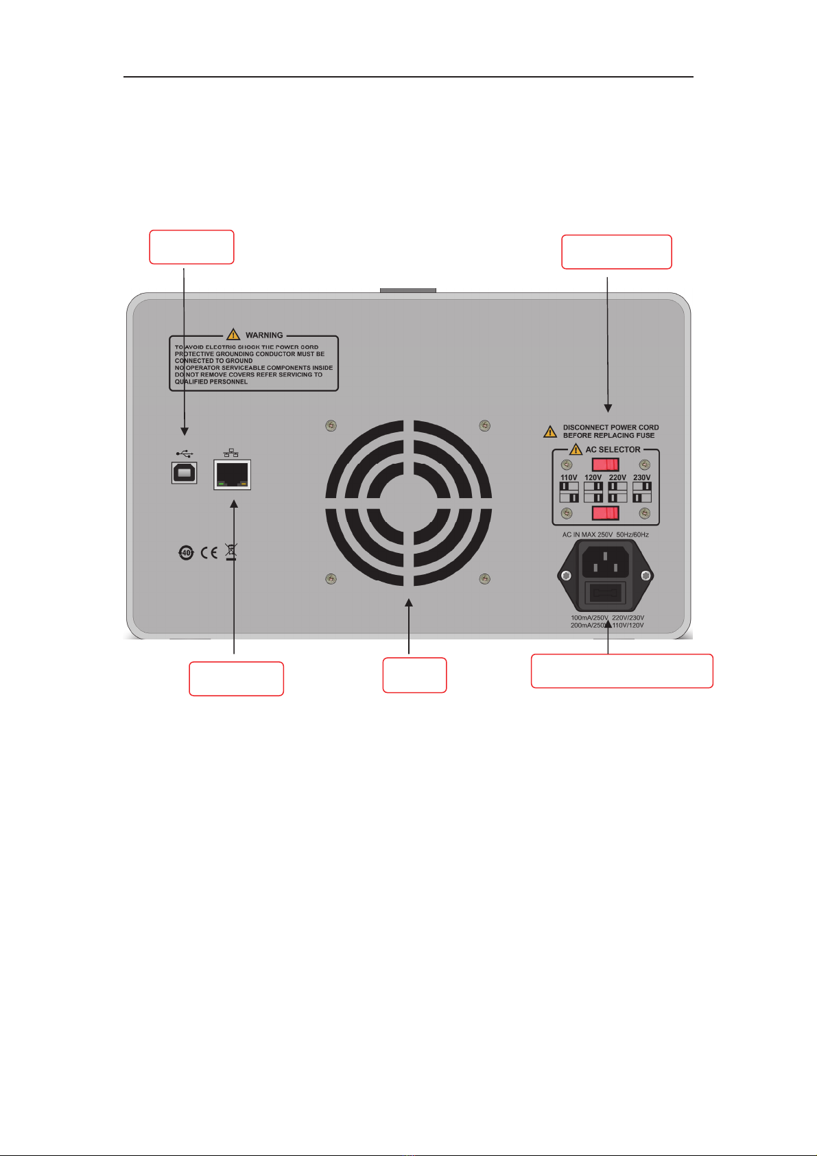
Back panel
Warning: For better heat emission, please do not block off the vent.
USB port
LAN port Vent Power input terminal
AC selector

PCE-PPS3300 series DC Power Supply User Manual 11 /23
2.2 Main interface
Chapter 3 Functions
3.1 Set value
Voltage setting:
Method 1: On main interface, press →menu button Voltage,rotate the knob and
directional key to change the number
Method 2: On main interface, on main interface, press →menu button Voltage
press the number key pad to input number directly, press the knob to confirm the
value. You can press to delete the value, press to exit the setting.
Current setting is similar to voltage setting method
Note: Channel 3 output voltage: 5V, 3.3V, 2.5V, press the menu button to select
directly, or press to fast switch
Limit value Set value
Load value
PCE-PPS3300 series DC Power Supply User Manual 12 /23
3.2 Output method
Adaptive mode: Output voltage/current varies according to the change of the load.
For example, set value: voltage: 10V, current: 2A, if the current ≤2A, the instrument
will enter into constant voltage operation automatically, the output voltage keeps
10V. If the current>2A, the instrument will enter into constant current operation, the
output current keeps 2A.
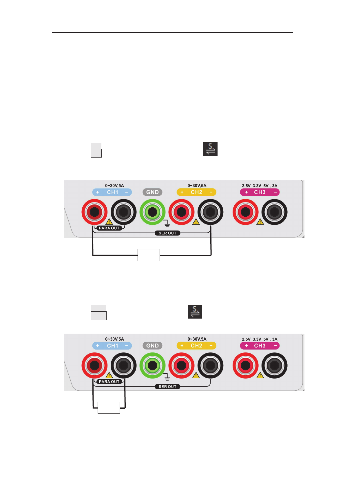
3.3 Series/parallel connection
Series connection
Series connection can provide higher output voltage which is the sum of that from
Channel 1 and Channel 2.
Run as: Press SER button, there is LED indicator with on the display screen.
Wiring method:
Parallel connection
Parallel connection can provide higher output current which is the sum of that from
Channel 1 and Channel 2.
Run as: Press PARA, there is LED indicator with on the display screen.
Wiring method:
Caution: Pay attention to the polarity.
R
R

PCE-PPS3300 series DC Power Supply User Manual 13 /23
3.4 Tracking function
When you open the tracking function, appears on the display. If you change
the voltage or current of one channel, the other will change accordingly. This
function is mainly used for operational amplifier or generating equivalent voltage.
Run as: On main interface, press the menu button Track, appears on the
display screen.
Note: Tracking function is only available on programmable value not the practical
output value.
3.5 Output tracking
After enabling tracking function, press UTILITY to turn on/off output tracking
ON: When you turn on/off the output of one channel, the other one will run
accordingly.
OFF: When you turn on/off the output of one channel, the other one will not be
influenced.
3.6 Timer and delayer
When you turn on the timer, the instrument will output the set value of
voltage/current (maximum 10 groups). Users can set the group quantity, voltage,
current and time. Output voltage and current are no longer restricted by the limit
value when the timer is on.
When you turn on the delayer, the instrument will turn on/off the output (maximum
10 groups) according to the status and delay time set before. Users can set the group
quantity, status and delay time of each group.
Users can save the edited parameters (Data format, timer:*.tmr. Delayer:*.dlr).
Setup:
Press TIMER/DELAYER to cycle switch Timer→Delayer→Exit
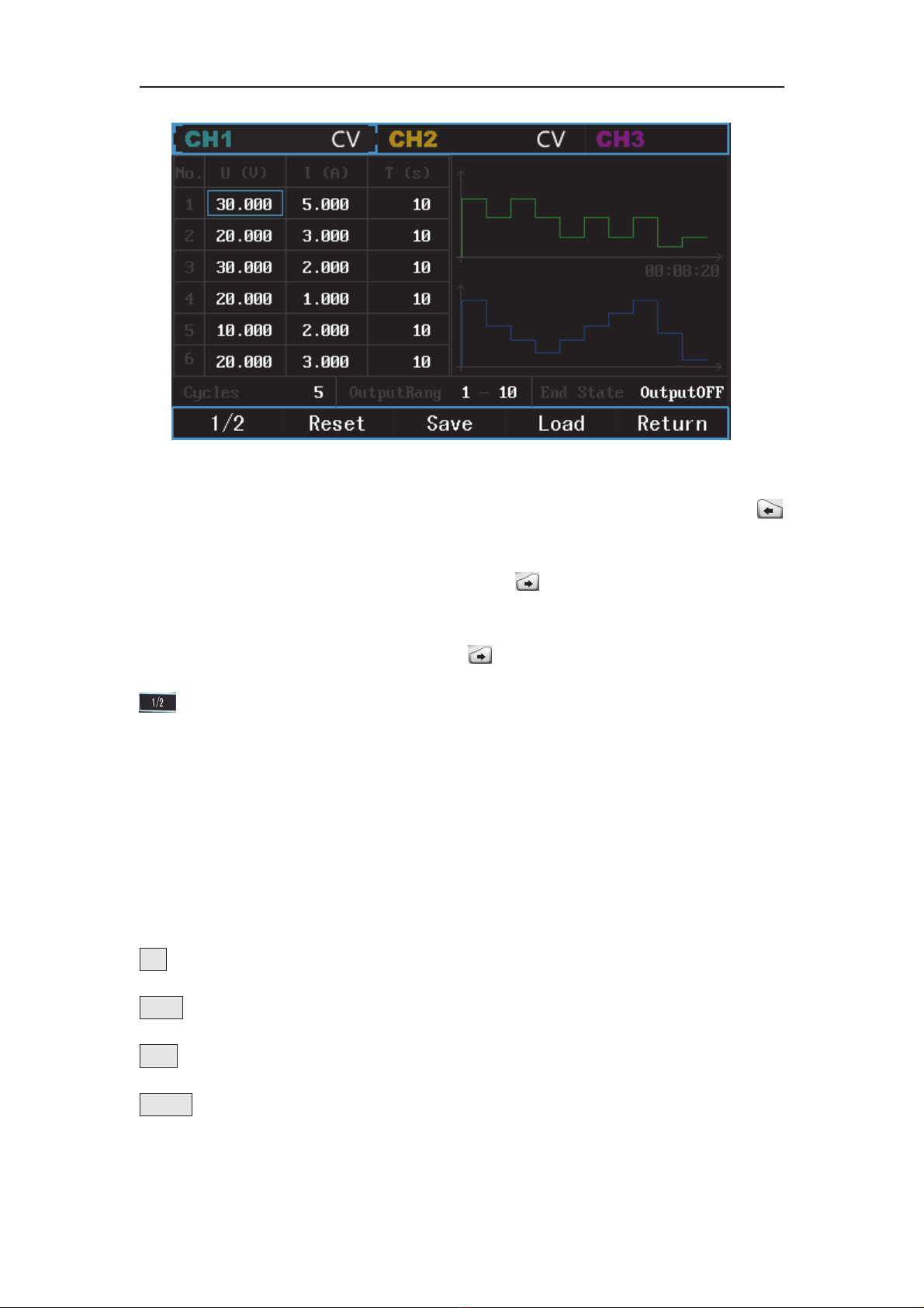
When you open the timer:
PCE-PPS3300 series DC Power Supply User Manual 14 /23
Voltage:
Press the number keypad to input value, press the knob to confirm. You can press
to delete the input value.
Current:
After the voltage setting, rotate the knob or press to switch to current bar,
number input method is similar to voltage.
Time setting is similar to voltage and current. After the setting of the first group,
rotate the knob or press the directional key to the next group. There are 10
groups in total, 6 in the first page. You can switch to the rest 4 groups by pressing
.
Note: On Channel 3 setting, press the knob to cycle switch the fixed voltage.
Output setting:
After the setting of voltage, current and time for each group, use the knob or the
number keypad to input output times: 0~9999; Output range means output groups.
Output status: output hold/output off. Output hold means when the timer is off, the
instrument remains the last output status. Output off means output is 0.
Menu buttons:
1/2:flip over
Reset:reset all data to 0
Load:Load all timer data saved in the instrument.
Return:return to main interface.
PCE-PPS3300 series DC Power Supply User Manual 15 /23
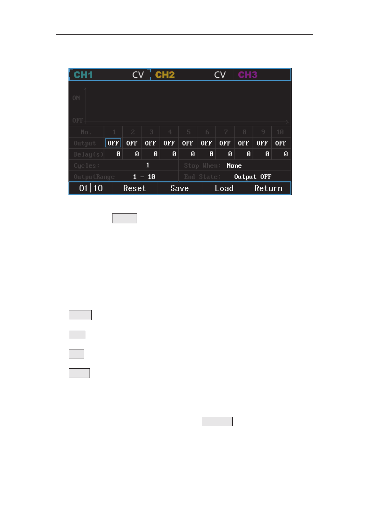
Delayer interface:
Output: Press 01|10 or press the knob to fast switch ON/OFF.
Delay: Please refer to voltage setting.
Output times: Please refer to timer
Stop when:none, <voltage value, >voltage value, <current value, >current value,
<power value or >power value.
Output range: groups quantity
End state: Output OFF/Output Hold, output hold means the output remains still
even the delayer is off. Output off means output zero signal.
Menu buttons:
01|10:Fast switch the output status
Reset:Reset all data to 0
Load:Load all delay data saved in the instrument.
Return:Return to main surface
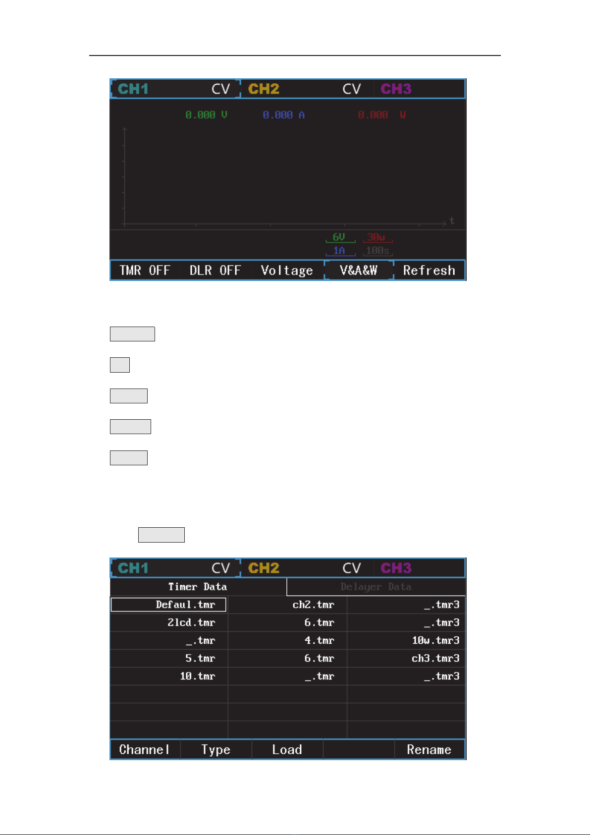
3.7 Waveform display
After the setting of timer and delayer, press WaveDisp to enter into waveform
display interface:
PCE-PPS3300 series DC Power Supply User Manual 16 /23
Menu button:
TMR OFF:Timer ON/OFF
DLR:Delayer ON/OFF
Voltage:Select voltage as the waveform type in display
V&A&W:Voltage, current and power are displayed at the same time
Refresh:Delete the waveform display
3.8 Storage
Press STORAGE to enter into storage interface
PCE-PPS3300 series DC Power Supply User Manual 17 /23
Menu button:
Channel:Select channel, or press , , to select channel.
Type:Switch between timer and delayer data.
Load:Load the saved data on timer or delayer interface.
Rename:Rename the data. Press RENAME, rotate the knob, input the name and
press confirm
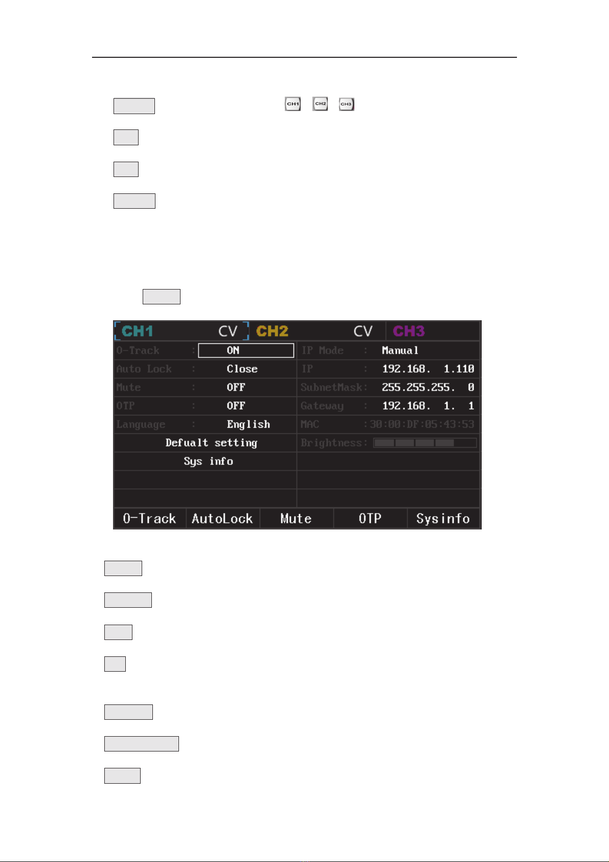
3.9 Utility
Press UTILITY to enter into utility setting interface:
Menu button:
O-track:Output tracking. Refer to Section 3.6
AutoLock:10mins/30mins/1hr
Mute:Buzzer ON/OFF
OTP:ON/OFF, to protect the instrument, the power supply will automatically shut
off when the inner temperature is relatively high.
Language:Chinese/English
Default setting:Reset to default setting.
Sysinfo:Display system information: model, software version, firmware version,

PCE-PPS3300 series DC Power Supply User Manual 18 /23
serial number, production date, boot times and working hours.
Brightness:Adjust brightness of the backlight
IP mode:Auto/Manual
IP address
IP address format: nnn.nnn.nnn.nnn. Range of the first nnn is 1 to 223, the other
nnn is 0 to 255. It is suggested that you ask the network administrator for an
available IP address. Select IP address, use the number keypad and directional
key to input IP address. This setting will be saved in NVM. When you start up the
instrument next time, the instrument will load the IP address automatically.
Sub-net mask
Sub-net mask format: nnn.nnn.nnn.nnn. Range of nnn is 0 to 255. It is suggested
that you ask the network administrator for an available Sub-net mask. Select
Sub-net mask, use the number keypad and directional key to input Sub-net mask.
This setting will be saved in NVM. When you start up the instrument next time,
the instrument will load the Sub-net mask automatically.
Gateway
Gateway format: nnn.nnn.nnn.nnn. Range of nnn is 0 to 255. It is suggested that
you ask the network administrator for an available gateway. Select Gateway,use
the number keypad and directional key to input gateway. This setting will be
saved in NVM. When you start up the instrument next time, the instrument will
load the gateway automatically.
MAC
MAC starts from 0, increase by 1 each time, therefore, the physical address
space increases linearly.
3.10 Keypad lock
To avoid faulty operation, press Lock/Unlock to lock the keypad, the button is
lightening. Press this button again to unlock the keypad and the light is off.
PCE-PPS3300 series DC Power Supply User Manual 19 /23
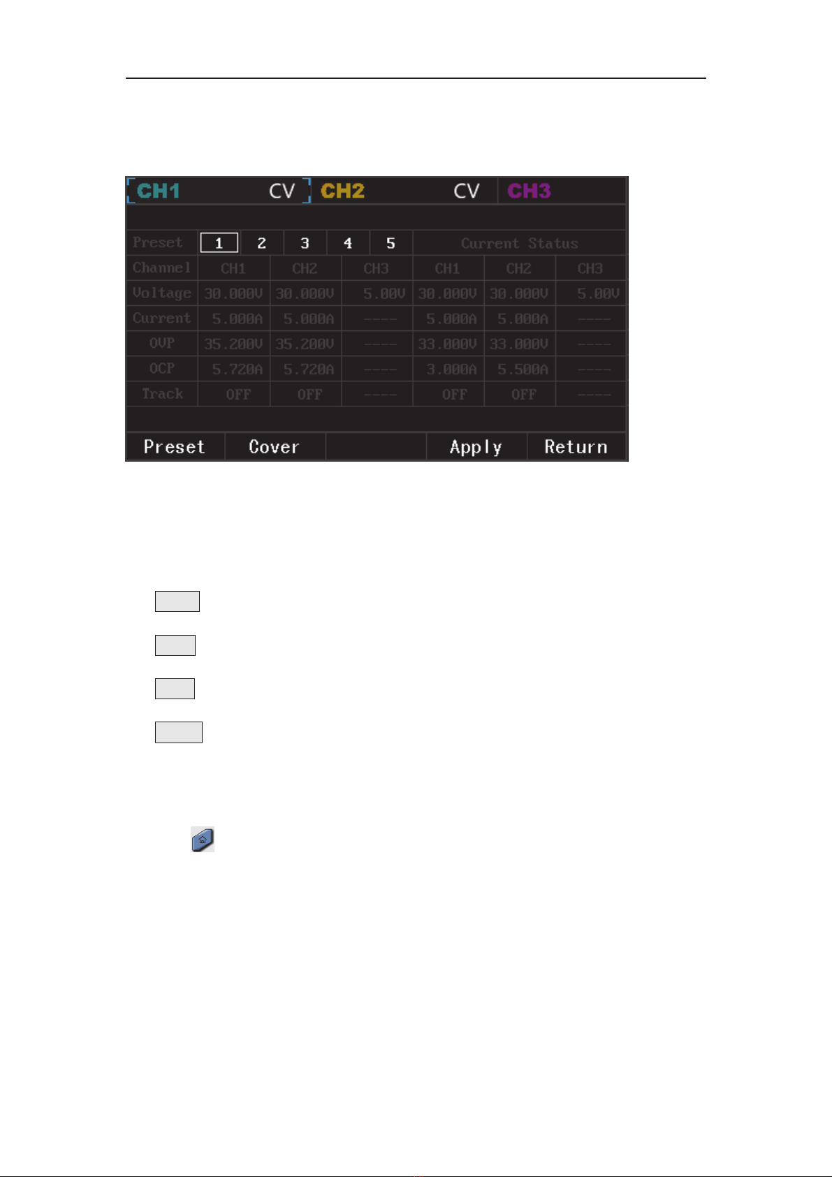
3.11 Preset
Press “PRESET” to display the preset parameters:
You can preview preset status value and present status value. The present status
value can be used to cover the preset value.
The present status value is the set value on the main interface.
Menu button:
Preset:Group selection, or you can use the knob to select.
Cover:Cover the preset status value with the present value
Apply:Apply the preset value to the present value.
Return:Return to the main interface.
3.12 Home page
Press at any page to return to the home page:

PCE-PPS3300 series DC Power Supply User Manual 20 /23
This manual suits for next models
2
Table of contents
Popular Power Supply manuals by other brands

Videx
Videx 520MR Installation instruction

Poppstar
Poppstar 1008821 Instructions for use

TDK-Lambda
TDK-Lambda LZS-A1000-3 Installation, operation and maintenance manual

TDK-Lambda
TDK-Lambda 500A instruction manual

Calira
Calira EVS 17/07-DS/IU operating instructions

Monacor
Monacor PS-12CCD instruction manual


