PCS Electronics CyberMax8000 Plus User manual
Brought to you by PCS Electronics, www.pcs-electronics.com
CyberMax8000+ STEREO/RDS
High performance DSP FM tereo encoder/proce or with 114x
over ampling
Manual

Brought to you by PCS Electronics, www.pcs-electronics.com
I M P O R T N T N O T E
Upon receiving your order inspect the packaging material and unit for apparent damage.
ny damage should be reported immediately so we can make a claim with the shipping
company. Take photos, if you can, they can be used as a proof.
Mains cable is typically not included with our mains power supplies and units. Since these
cables vary from country to country and we had trouble finding the exact type we decided
against including them, especially since finding them is so easy and cheap locally. They
can be obtained in any radio/computer/hardware shop at the cost of about 1 US$. It is the
type used in your PC for mains power.
Study local regulations and ensure you are operating in compliance.
Never ever operate any transmitter or amplifier without a properly tuned antenna!

Brought to you by PCS Electronics, www.pcs-electronics.com
Table of Contents
Introducing the CyberMax8000+ STEREO/RDS encoder......... 5
Why is CyberMax8000+ Stereo/RDS so great?.............................. 5
Technical specifications: ................................................................. 6
Thank you for purchasing CyberMax8000+ stereo rds encoder...... 6
Wiring, setup and testing.......................................................... 7
Front and back panel layout............................................................ 7
First power-up ................................................................................. 8
Setting up levels.............................................................................. 8
Some useful tips....................................................................... 9
Mains power supply and mains power cable................................... 9
Digital audio streaming.................................................................... 9
Which FM transmitters can be connected to CyberMax8000+ DSP
stereo /rds encoders ....................................................................... 9
CyberMax8000+ LCD control module .................................... 10
Lcd control module menu system: Power and DSP functions....... 10
<STEREO MODE> ....................................................................... 10
<TREBLE> and <BASS> .............................................................. 10
Compressor Settings (only with DSP stereo encoders) ................ 11
<LCD CONTRAST> ...................................................................... 12
Left and right channel volume ....................................................... 12
<FIRMWARE VER>...................................................................... 13
Introducing the CyberMax8000+ STEREO/RDS encoder....... 14
Under the hood: SE8000DSP+ board layout .......................... 14
Board layout.................................................................................. 14
Troubleshooting ..................................................................... 31
Troubleshooting ............................................................................ 31
Principles of operation............................................................ 34
INTRODUCTION - PRINCIPLES OF OPERATION ...................... 34
Some facts about stereo ............................................................... 35
The transmitter.............................................................................. 35
The receiver .................................................................................. 35

Brought to you by PCS Electronics, www.pcs-electronics.com
Circuit description ......................................................................... 35
Appendix B – Warranty and legal info .................................... 36
Warranty and servicing! ................................................................ 36
Legal info ...................................................................................... 36
Limitation of liability....................................................................... 36
Also available from www.pcs-electronics.com .............................. 37
Revisions and errata .............................................................. 38
Index ...................................................................................... 39

Brought to you by PCS Electronics, www.pcs-electronics.com
5
Introducing the CyberMax8000+ STEREO/RDS encoder
With DSP and digital audio input (USB) for completely noise-free audio experience
ased on the new SE8000DSP+ is a high performance stereo encoder with DSP digital processor, split supply rails
(via on- oard DC/DC), alanced input uffers, a fairly complex and incredi ly sharp filter with deep notch at
19KHz, pre-emphasis, limiter and LC MPX filter. Digital su system generates 19KHz pilot (32x oversampling) and
generates DSB signal. 114x oversampled MPX ensures crisp stereo sound with excellent stereo separation. SE8000
DSP+ can e upgraded to RDS functionality simply y plugging-in a RDS IO oard with integrated USB remote control via
PC. It is perfect for a demanding roadcaster.
Cy erMax8000+ will make sure your signal stays where you want it, providing high quality audio with excellent channel
separation without causing interference to near y channels. High quality components and printed circuit oard assure 24/7
operation for years. In this manual you will find all of its exciting secrets.
Why is CyberMax8000+ Stereo/RDS so great?
- Perfect for any mono FM transmitter (turning it into stereo)
- Mix of analog/digital technology produces crisp natural sounding audio
- When digital audio input is used you can enjoy completely noise-free audio. Ground loops are gone. You have to hear it to
elieve it. You can now stream audio digitally directly from your PC/Laptop.
- Extremely sharp 15kHz low pass filters and a very deep notch at 19KHz!
- On- oard XLR connectors
- Pilot level and pre-emphasis now selecta le from the LCD
- Works either with separate LCD module or can e connected to LCD module of our exciters (requires new LCD type with
encoder)
- Balanced XLR or un alanced RCA audio inputs. This effectively eliminates annoying ground loops and hum.
- LC filtered MPX output signal.
- Built-in limiter, low pass filter and true compressor.
- Excellent stereo separation
- Support for RDS daughter oard for easy upgrade to RDS
- MPXin/MPXout/19KHz header connects to IO oard with 3 BNC connectors
- MAXLINK II makes it possi le to connect to FM exciter without any soldering
.
Chapter
1
B

Brought to you by PCS Electronics, www.pcs-electronics.com
6
Technical specifications:
Audio Response: 10Hz-15KHz, 15kHz lowpass filtered (standards require upper level at 15KHz max)
19KHz notch filter, >-60 dB typ
Precise pre-emphasis, 50uS, 75uS or none selecta le from LCD display
Audio Input Impedance: 10K, alanced or un alanced
Audio Input Level: 0 dB
Digital audio input: USB connector, Windows/Linux/Mac compati le
Distortion: <0.01%
S/N ratio: >85 dB
Separation: >60 dB typ.
Pilot Frequency: 19 KHz, DSP generated with 114x oversampling
Output Impedance: 75 Ohms
Power Requirements: 12-15VDC / 200mA
PC Board Size: 120x100mm
Audio connectors: all RCA jacks are mounted on the oard, XLR are mounted on oard
Power connector: 3-pin header, center is positive
Output level: 4V
Thank you for purchasing CyberMax8000+ stereo rds encoder
We hope you will enjoy it as much as we do and if you do remem er to tell your friends and colleagues a out it. Please feel free
to leave your comments at our we site or post your experience in our forum. And if you encounter a pro lem please let us
know so that we may improve our products, offer advice and suggestion. From all of us we wish you happy roadcasting!
Your PCS Electronics team

Brought to you by PCS Electronics, www.pcs-electronics.com
7
Wiring, setup and testing
Front and back panel layout
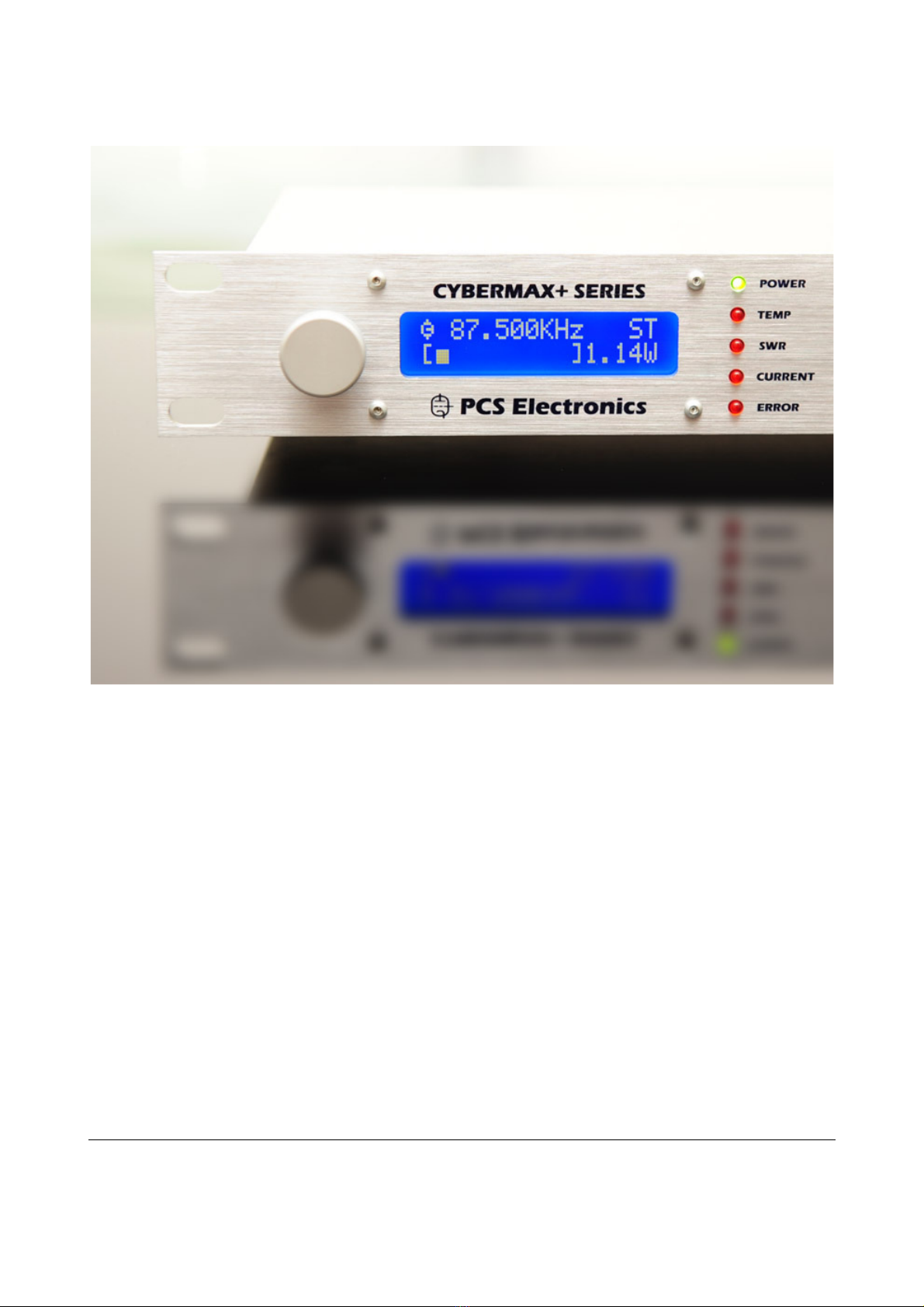
Front panel
Reference Function
1 Rotary utton or 3 keys
2 LCD display that lets you control the unit and monitor various parameters.
3 The green led. Green signals power is ON.
4 Red error leds.
5 Power switch
Description of front panel of Cy erMax8000+ stereo rds
Back panel
Reference Function
1 Power jack, center is positive. 12-15V DC, 3A (more for 25W model and up)
2 USB audio input (for PC)
3 Ventilation aperture, fan, not used for stereo processors
4 Antenna connector, BNC. Not used for stereo processors
5 BNC connectors for MPXin, MPXout and 19KHz pilot
6 RS232/USB for programming RDS parameters
7, 8 Audio inputs, RCA jacks for left and right channel.
9, 10 Balanced audio inputs, left and right channel XLR (Canon). Note XLR connectors are la eled wrong
(right is on the left and vice versa).
11 Not used for stereo processors
12 Optional Ethernet remote control port
Description of ack panel of Cy erMax8000+ stereo rds processors
Chapter
2
Brought to you by PCS Electronics, www.pcs-electronics.com
First power-up
Wiring up and testing transmitter is easy.
1. Place unit in a suita le well ventilated position. Connect audio inputs and connect MPX output to FM transmitters MPX
input, ensure all connectors are firmly secured. XLR ca les are more ro ust for inputs and are recommended.
2. Connect mains power supply and turn the unit on.
3. Turn on a radio receiver and set it to your intended transmitter frequency. Flip the POWER switch ON also for
transmitter and wait for the unit to turn on. Wait a few seconds for the power to ramp up. Your radio should now start
playing audio from your audio source or mute (if you did not connect any audio source yet).
4. You can now set MPX input level of your transmitter for correct deviation and verify audio performance. You should not
sound louder than other stations, in fact unless you have an expensive high performance software or hardware sound
processor you should sound a it quieter than other stations.
5. Verify whether the left and right channel are set correctly. This may not e important for music ut matters in movies.
Exchange channels if needed. To see audio levels set View type to display Audio Levels. Access menu View y pressing the
menu key or rotary utton until this is shown, than change value to Audio Levels.
6. If your unit supports RDS, you can set RDS PS (Station name – 8 characters) and RDS RT (RadioText – 64 characters)
and other RDS parameters. This requires connection to PC via USB or Ethernet to setup. Software setup is descri ed later
in this manual.
Setting up levels
Cy erMax8000+ stereo rds is very easy to setup. What we do have to do however is match the output level of the encoder
and input level of the transmitter so that the pilot tone (19 kHz) alone (no audio) gives a deviation of the exciter of 6.75 kHz
(9 percent). This automatically sets the remaining audio levels. If you’re using our line of FM exciters just connect the stereo
encoder to the transmitter, set encoder to Stereo, set audio level on the fm transmitter to zero and keep increasing it until
the stereo led on the receiver comes on.
Let’s assume that you don’t own an expensive peak:
1.) Disconnect one audio input source so that only one channel is connected. Apply audio to this source.
2.) Listen to the audio on a high-grade tuner and adjust the input volume pot for that audio channel so that the volume is
only half that of a commercial station. The reason we want this is to e sure we are inside the +/- 75 kHz andwidth. Over
deviation will cause degradation of the stereo separation. We now should have the encoder correctly setup with only one
channel of audio that is inside the +/-75 kHz andwidth so separation should e a le to e fine tuned without pro lems
such as over deviation affecting our measurements. Turn your amplifiers alance control so that you are listening to only the
channel with no audio on.
If everything is good and well then you should have this channel a lot quieter than the other channel. Turn the
amplifier up in volume so you can hear the crosstalk etween the channels. Now adjust trimmer (J) until the sound
in the opposite channel disappears or is at least arely noticea le. You should e a le to achieve your maximum
separation. You can now reconnect the other channel and apply your audio at the correct level. The encoder is now
aligned and ready for operation. DO NOT FORGET TO DISABLE PREEMPHASIS AT THE
TRANSMITTER WHEN YOU CONNECT IT TO THE STEREO PROCESSOR/ENCODER (failure
to do o re ult in very poor tereo eparation and di tortion).
Brought to you by PCS Electronics, www.pcs-electronics.com
Some useful tips
It is recommended that you read this section efore you power your unit up for the first time. Let us clear up some asics
you should know a out. You will also find some useful tips in our guides and forum at http://www.pcs-electronics.com.
Here is what you need to consider to get the est from your stereo encoder:
Mains power supply and mains power cable
Do not underestimate the importance of mains power supply, despite a undance of all kinds of cheap units availa le today
they unfortunately do not always meet requirements. What you need is a sta ilized DC 15V mains power supply that can
supply at least 100mA of continuous current without overheating, introducing uzzing, dropping the voltage down elow
12V (a classic case) or acting up in other way. Whenever in dou t please uy our mains power supply.
Digital audio streaming
If you want to drive your audio digitally, connect USB ca le to the USB port on the computer and the stereo encoder. Your
PC will detect the sound interface automatically. You can now play your audio digitally. In your media player look under
options and make sure you output your audio to the “USB audio adapter”. Whatever you play will e heard via your FM
transmitter.
Which FM transmitters can be connected to CyberMax8000+ DSP stereo /rds encoders
Any FM transmitter with MPX input.
Chapter
3

Brought to you by PCS Electronics, www.pcs-electronics.com
CyberMax8000+ LCD control module
Basically there are three push- uttons availa le for the menu system; UP, DOWN and MENU. By pushing UP or
DOWN you change the selected parameter in corresponding direction. The third utton (MENU) gives you an option to
select and setup many of the options and DSP functions of this unit. LCD display with rotary encoder has a different setup,
you need to press the rotary utton to select menu. Rotating up or down changes the paremeter value.
Lcd control module menu system: Power and DSP functions
The UP and DOWN keys are used to change parameter values. In normal mode the LCD simply shows audio level for
oth channels. Menu key can e used to enter the menu mode, repeatedly pressing this key rings up the following menus:
<STEREO MODE>, <TREBLE>, <BASS>, <COMPRESSION>, <THRESHOLD>, <ATTACK>, <DECAY>,
<INTEGRATION>, <LCD CONTRAST>, <RIGHT CH VOL>, <LEFT CH VOL>, <PILOT LEVEL>, ,
<PREEMPHASIS>, <FIRMWARE VER>. Pressing the UP or DOWN key selects the desired parameter and allows you
to modify its value. Another press on the MENU key and you’re ack to the normal mode. Note that all these settings
except power and frequency are already set as they should e so changing them should not e necessary and is not
recommended. Best values are marked with D, such as <50uS D>.
<STEREO MODE>
You can set your transmitter to MONO or STEREO here.
<TREBLE> and <B SS>
This option allows you to set the amount of TREBLE and BASS in your audio. Recommended values are marked with (D).
Setting tre le
Setting ass
Chapter
4
Brought to you by PCS Electronics, www.pcs-electronics.com
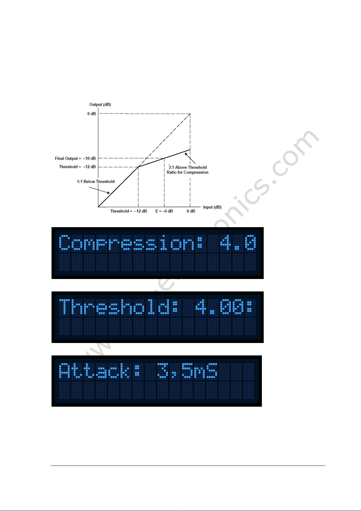
Compressor Settings (only with DSP stereo encoders)
A num er of MENU settings control the operation of the compressor. Lets assume that the audio signal enters the
transmitter at some low level. Compressor does nothing to the signal until at one point as the input signal increases the
signal reaches the compression threshold. Digital signal processor starts compressing the signal eyond that point. The
higher the compression ratio the higher the compression. For example, compression ratio of 1:
∞
would in effect e a
limiter.
Explanation of the compressor settings
Setting the compression level
Setting the compression threshold
Setting the attack time, this is the time etween the input signal and the actual response of the compressor
Brought to you by PCS Electronics, www.pcs-electronics.com
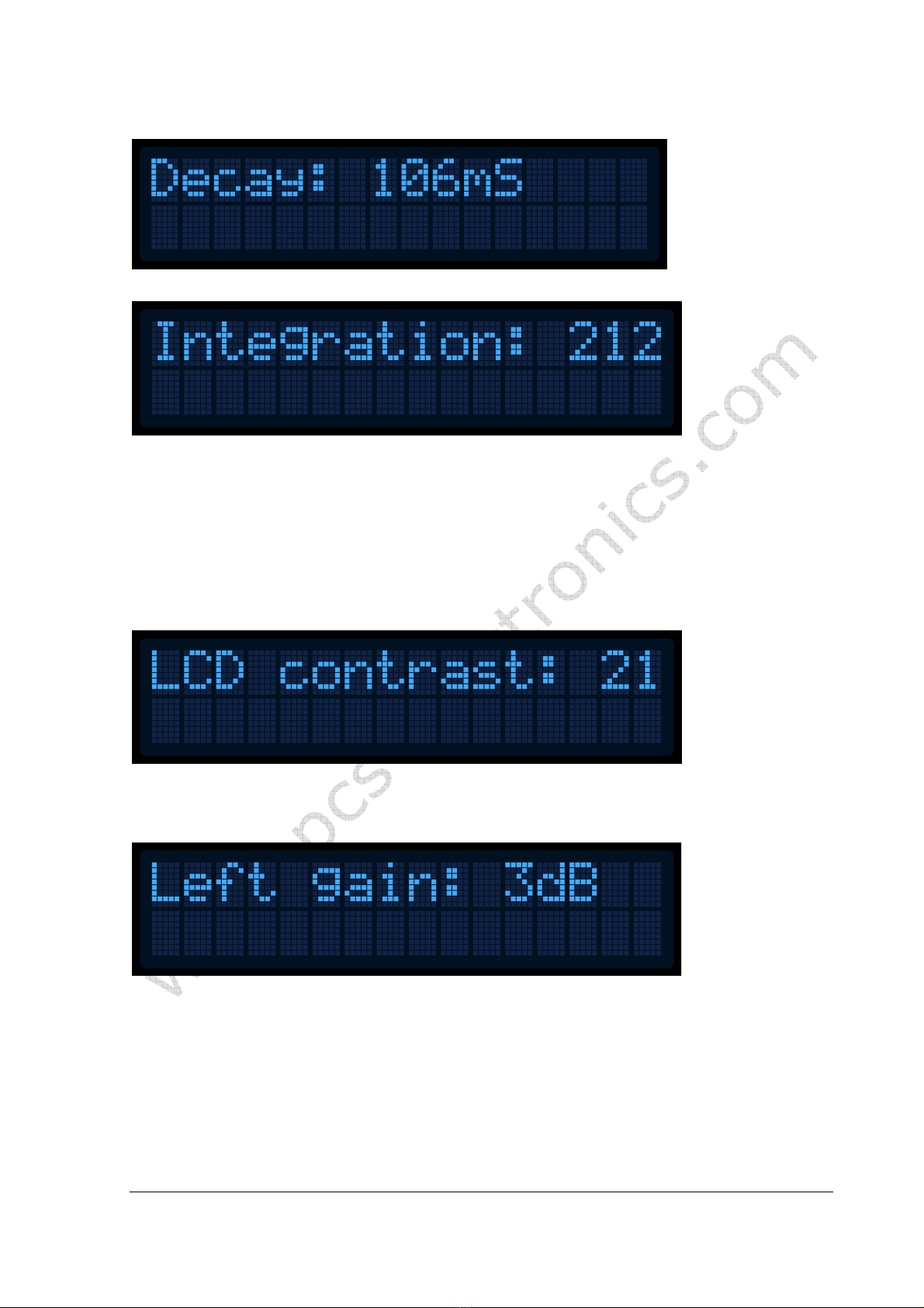
Setting the decay time, this is the time the compressor needs to respond after the input signal falls ack to normal level ( elow threshold).
Setting the integration interval, this is the time the DSP evaluates the signal to esta lish whether it should respond or not
Integration interval determines the energy needed to trip the compressor. In simple words; it determines how long the audio
needs to e loud for the compressor to respond y reducing the gain. This is not to e confused with attack time. Attack
time of 50ms means the compressor will respond in 50ms after the signal spike is detected, regardless of duration of that
spike, even if it is just a very short event. With longer integration interval, on the other hand, compressor only responds if a
long spike or a su stantial num er of spikes is detected (meaning more signal energy).
<LCD CONTR ST>
Select for the est visi ility. Contrast is slightly affected y am ient temperature and you can adapt it to your needs here.
Changing contrast
Left and right channel volume
This option allows you to precisely adjust the input sensitivity of oth audio channels. This is very useful when your audio source has either too
high or too low output level.
Changing right input channel gain

Brought to you by PCS Electronics, www.pcs-electronics.com
<FIRMW RE VER>
This option allows you to display current LCD module firmware version.
Firmware version
Brought to you by PCS Electronics, www.pcs-electronics.com
Introducing the CyberMax8000+ STEREO/RDS encoder
Under the hood: SE8000DSP+ board layout
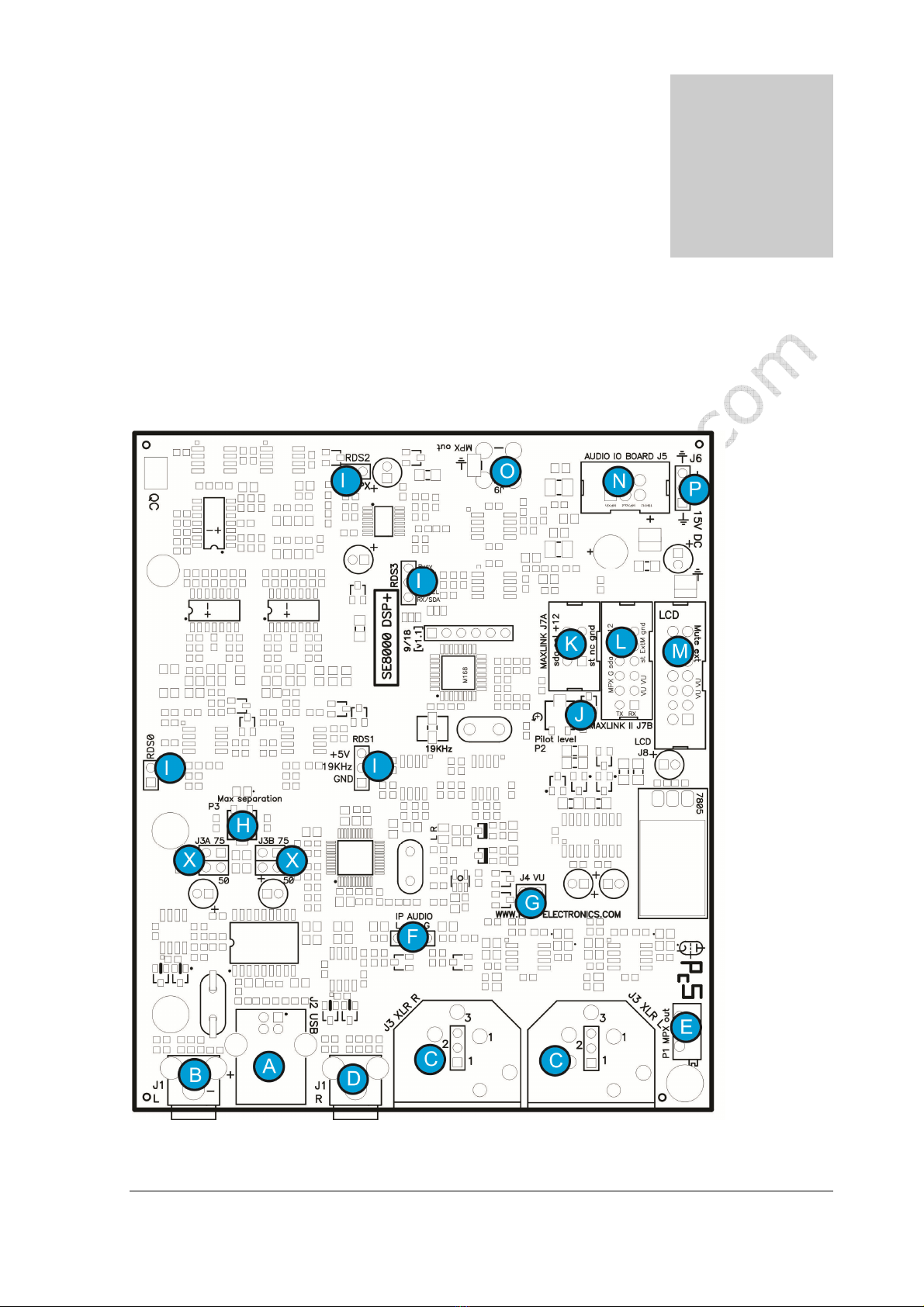
Board layout
SE8000+ oard layout
Chapter
5
Brought to you by PCS Electronics, www.pcs-electronics.com
Ref.
Function
A Digital audio input, USB
B,D Left and right analog audio input, RCA
C Left and right XLR connectors
E MPX out level, adjusta le from inside (make holes into enclosure)
F Connection to optional Ethernet audio streaming (Barix). Audio input.
G You can connect VUMAX-1 led vu-meter unit here, it will show audio levels as ar graphs. The 2 remaining ar
graphs can e connected to FM exciter to show power and SWR.
H Separation adjustment. You can maximize for est stereo separation here.
I Optional RDS daughter oard is plugged in here.
J Stereo pilot level can e adjusted here (frequency is adjusted with 19KHz trimmer to the left)
K MAXLINK connector (for interfacing with MAXPRO2015, 6000 or 7000 series). DO NOT CONNECT
THIS TO LCD DISPLAY AS THAT CONNECTOR IS FOR RS232.
L MAXLINK II connector (for interfacing with MAXPRO8015, MAXPRO9015)
M LCD control unit can e connected here (when used as stand-alone).
N Connects to optional IO oard with three BNC connectors (19KHz, MPX in and MPX out).
O MPX out, this goes to FM exciter audio input (if MAXLINK II is not availa le)
P Power supply (15V, 0.5A). Not needed when MAXLINK II is used.
X Pre-emphasis jumpers. Set to 75 for USA and 50 for most of the world.
Description of various elements of the SE8000DSP+ stereo encoder oard
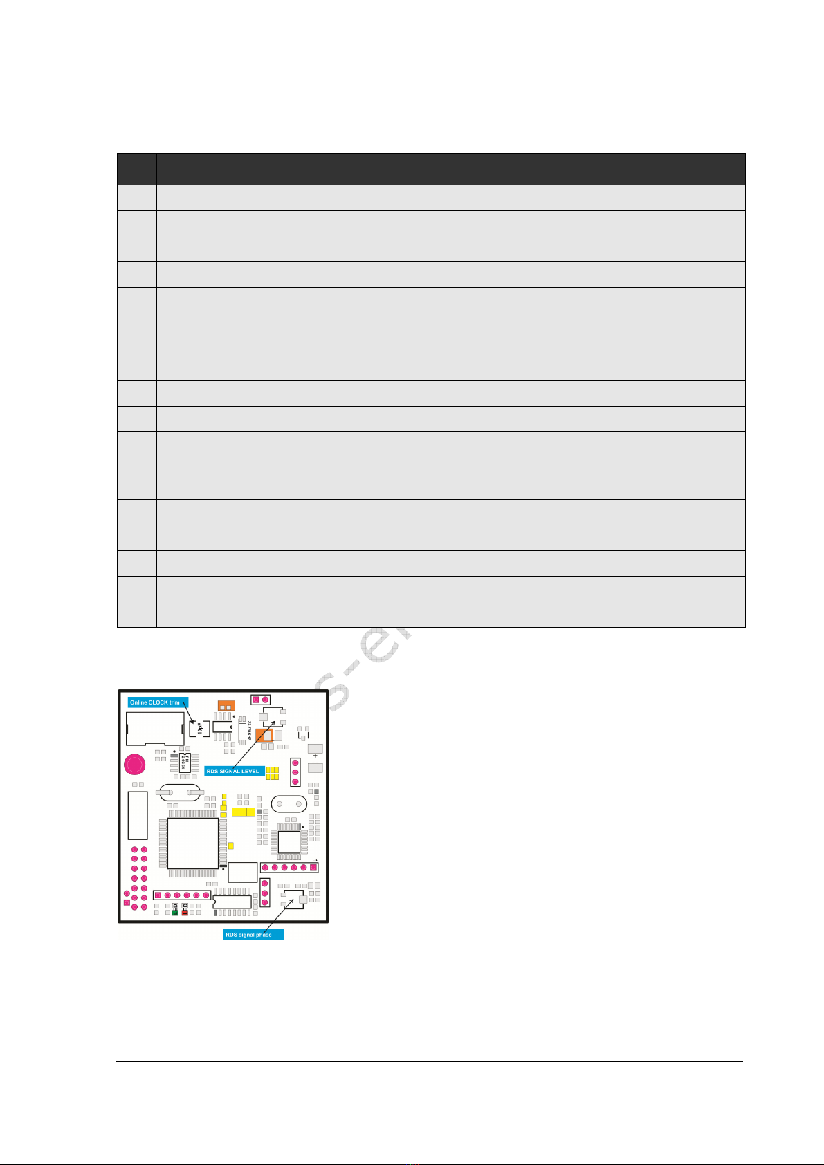
RDSM X8000 MICRO RDS board layout
RDSMAX8000 micro rds encoder oard layout

Brought to you by PCS Electronics, www.pcs-electronics.com
Ref.
Function
A Level of RDS signal. Set it as low as possi le
B Phase of RDS signal, set for minimal noise
C On oard clock trim, adjust if clock lags or advances after several days
Description of various elements of the RDSMAX8000 micro RDS encoder oard

Brought to you by PCS Electronics, www.pcs-electronics.com
WINDOWS CONTROL PROGR M
SOFTW RE INST LL TION ND COMMUNIC TION SETUP
Use the USB port!
Our processors have two USB ports, one serves as USB audio input. That one should not e used for remote control!
Installing USB driver
If you want to use USB to program and control our transmitter via PC, download the USB COM port driver, you can find
it here: https://www.pcs-electronics.com/shop/fm-transmitters/cy ermax-fm-transmitters/cy ermaxfm-se-v3-15w-and-
25w/ (look under additional information ta )
Download the USB driver for your operating system and run the setup file. Wait for the following screen (or very similar) to
appear and select the installation directory ( est left alone at default location). Click Install and wait for the installation to
finish.
Installing USB driver
Configuring USB driver
In Windows go to Start > Settings > Control Panel > System > Hardware ta > Device Manager (This can vary depending on your Windows version). You
should have something like this on your screen at this point:
Configuring Com port for USB driver
Take note of the COM port num er here, you will need it later to configure the COM port inside Cy erMaxFM+ control
program for Windows. If you wish to change this port right click on the PCS USB-COM or whatever Windows detected it
Chapter
6
Brought to you by PCS Electronics, www.pcs-electronics.com
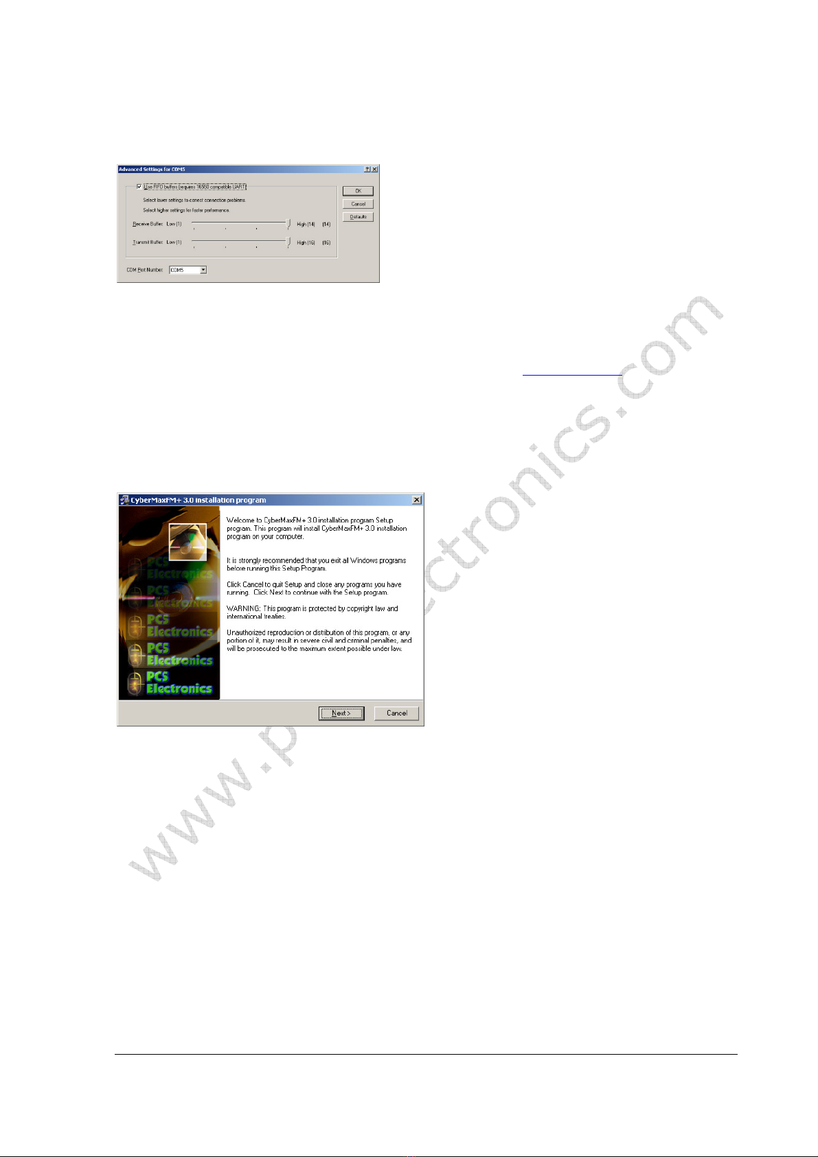
as, than select Properties. Now select the Port settings ta and click Advanced. Note you can set the COM port num er as
you wish:
Configuring Com port for USB driver
Installing correct program for controlling your FM transmitter
We are going to use a program that normally serves to control the FM transmitter, ut when used for stereo processor the
only thing that will work is the RDS encoder section. Everything else (DSP stereo parameters) will need to e set via LCD
display. Download the CyberMaxFM V6.4 etup program from the page mentioned earlier (or newer version, if
availa le). We also know which COM port it is from previous step.
Software installation
Download the latest setup file from the links a ove. Once you have the setup file run it and install the program on your
computer. This process is very straight-forward and should only take a few minutes. Wait for the installation to complete
and click Finish when done.
Welcome screen (from previous version of software)
Once the installation is done you are ready to start the program. But efore you do please esta lish physical connection
etween the transmitter and the PC. Alway connect and power up the proce or BEFORE you tart the Window
control program! Failing to do thi can cau e the program to freeze (you will have to clo e it and tart it up
again). Al o, clo e the Window control program before powering off the tran mitter.

Brought to you by PCS Electronics, www.pcs-electronics.com
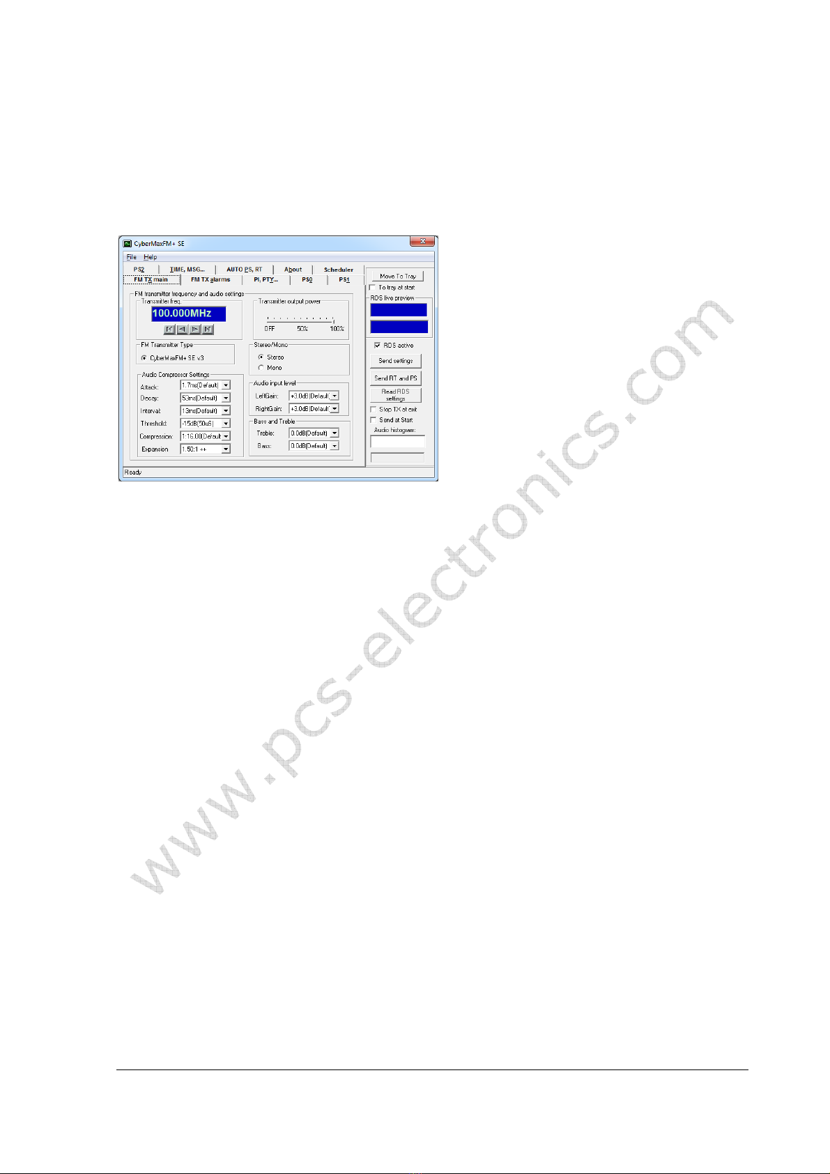
Cy erMaxFM+ remote control software, depending on your model this screen can differ a little.
As you can see this program lets you control all the parameters of your FM transmitter including RDS parameters which is
what we need.
Setting up com port in CyberMaxFM+ program
The only setup required is minimal. Start the Cy erMaxFM+ program, the icon should now e on the desktop. Now click
File and Setup. The following window will open. It i be t to et COM port manually a the Auto can feature doe
not alway work correctly (same goes for test tool).
Set COM port for remote control.
Brought to you by PCS Electronics, www.pcs-electronics.com
Testing the connection
The easiest way to test the connection is to try to send data to the processor. If there is an error message you’ll know
something is wrong. Also, when you change PS the station name on receiver will e changed.
FM TX main tab – transmitter setup
FM transmitter setup
Not needed when used to control stereo processor
FM transmitter type
Not needed when used to control stereo processor
FM transmitter frequency
Not needed when used to control stereo processor
Transmitter output power
Not needed when used to control stereo processor
Stereo/Mono
Not needed when used to control stereo processor, change via LCD display.
udio input level
Not needed when used to control stereo processor, change via LCD display.
Bass and Treble
Not needed when used to control stereo processor, change via LCD display.
udio Compressor Settings (only with DSP stereo encoders)
Not needed when used to control stereo processor, change via LCD display.
FM TX alarms
Table of contents
Popular Media Converter manuals by other brands


H&B
H&B TX-100 Installation and instruction manual

Bolin Technology
Bolin Technology D Series user manual

IFM Electronic
IFM Electronic Efector 400 RN30 Series Device manual

GRASS VALLEY
GRASS VALLEY KUDOSPRO ULC2000 user manual

Linear Technology
Linear Technology DC1523A Demo Manual

Lika
Lika ROTAPULS I28 Series quick start guide

Weidmuller
Weidmuller IE-MC-VL Series Hardware installation guide

Optical Systems Design
Optical Systems Design OSD2139 Series Operator's manual

Tema Telecomunicazioni
Tema Telecomunicazioni AD615/S product manual

KTI Networks
KTI Networks KGC-352 Series installation guide

Gira
Gira 0588 Series operating instructions

Lika
Lika SFA-5000-FD user guide