PCS Electronics CyberMax FM+ 15W User manual
PCS Electronics
www.pcs-electronics.com
CYBERMAX FM+ 15W (v 11/2007)
This innovative high performance FM broadcasting transmitter with stereo and RDS capability is available in a
wide range of configurations at an unbeatable price/performance ratio. Designed with SWR and TEMP
protection and guaranteed to offer excellent performance, DSP processing, spectral cleanliness and ruggedness,
as well as fairly simple handling. High quality components and manufacturing ensure 24/7 operation for years.
Technical specifications:
- RF Output Power: 0 to 15 Watts (10-15W typ, digitally adjustable with keys)
- Output connector: BNC (N adapters freely available)
- Output Impedance: 50 Ohms
- Audio input impedance: 10Kohms balanced, 10Kohms unbalanced
- Frequency Range: 87.500-108.000MHz (Japanese or other band on request)
- PLL steps: 6.25 KHz (12.5/50/100)
- Frequency stability: +/- 100Hz
- Audio Frequency Response: 35Hz – 75 KHz @ -3dB
- Stereo separation: > 50dB, depending on model, DSP version performs best
- Audio low pass filter: Yes, all models (best in DSP models)
- Limiter: Yes, all models (best in DSP models)
- Pre-emphasis: Yes, precision 50uS, 75uS or none for all models
- DSP: Yes, in models denoted with DSP
- RF output ruggedness: SWR protection, TEMP protection
- Spurious/Harmonic rejection: Harmonics: >-60dB, Spurious: -90dB
- Power Supply: 13.8-15V/3A or car battery, mains power supply available as an option
- Ultra Stable, Ultra Clean Output
- SWR protection: fold-back, unit reduces power as the SWR raises
- TEMP protection: fold-back, unit reduces power as the temperature raises
- Polarity protection: Yes, diode + fuse
- No Expensive Test Equipment required to setup
- Fuse type: F3A/250
2
Why is this transmitter so great?
- True wideband no-tune operation (no tuning required to make it work, just set the frequency and antenna)
- Built-in SWR and TEMP protection for peace of mind
- High power (10-15W typ)
- Digital output power adjustment (with up/down keys)
- DSP model offers extremely sharp audio filters and complete control over audio parameters via LCD menu system
- It can be powered by a car battery for convenience
- Now with new stereo encoder, new RDS encoder and completely new firmware (new functions)
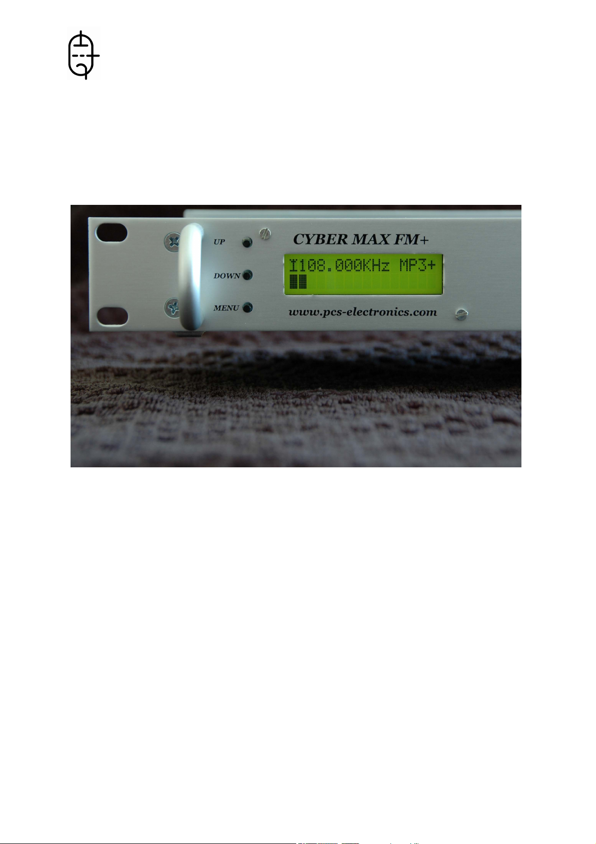
The front panel (left to right)
- 3 menu keys, up, down and menu, for navigating the menu system and changing various settings, including
frequency
- LCD display, shows various settings and makes it possible to change them.
- RED led diode shows error conditions (High SWR, PLL unlock or high TEMP). This LED also lights shortly after
changing the frequency or just after the power up, But than turns and remains off during normal operation.
- GREEN led diode shows power-on condition.
- ON/OFF switch serves as a main power switch
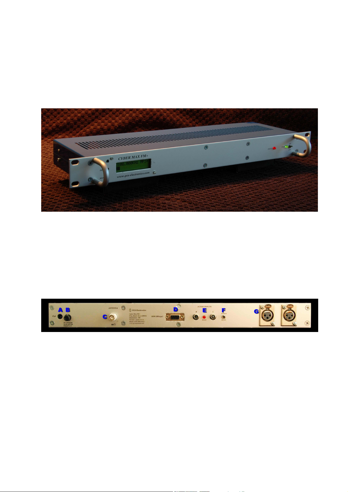
The back panel (left to right)
A: DC power supply jack, 13.8-15V (3A minimum). 15V is required to reach full output power.
B: Fuse, always replace with same type, which is 3F/250
C: Antenna output connector (BNC). NEVER operate this transmitter without a matched antenna.
D: RS232 connector for RDS encoder (only RDS capable models)
E: Unbalanced stereo audio inputs (RCA jacks). Connect to mixer, computer, CD player or other audio source.
F: MONO/STEREO switch.
G: Balanced stereo audio inputs (XLR jacks). Connect to mixer, computer, CD player or other audio source. XLR to
RCA converters are available as well as an option.
NOTE: Latest models come with new features. There is an optional USB port for RDS encoder and 3 optional BNC
connectors for MPXin, MPXout and 19KHz pilot. The photo above has not been updated yet.
3
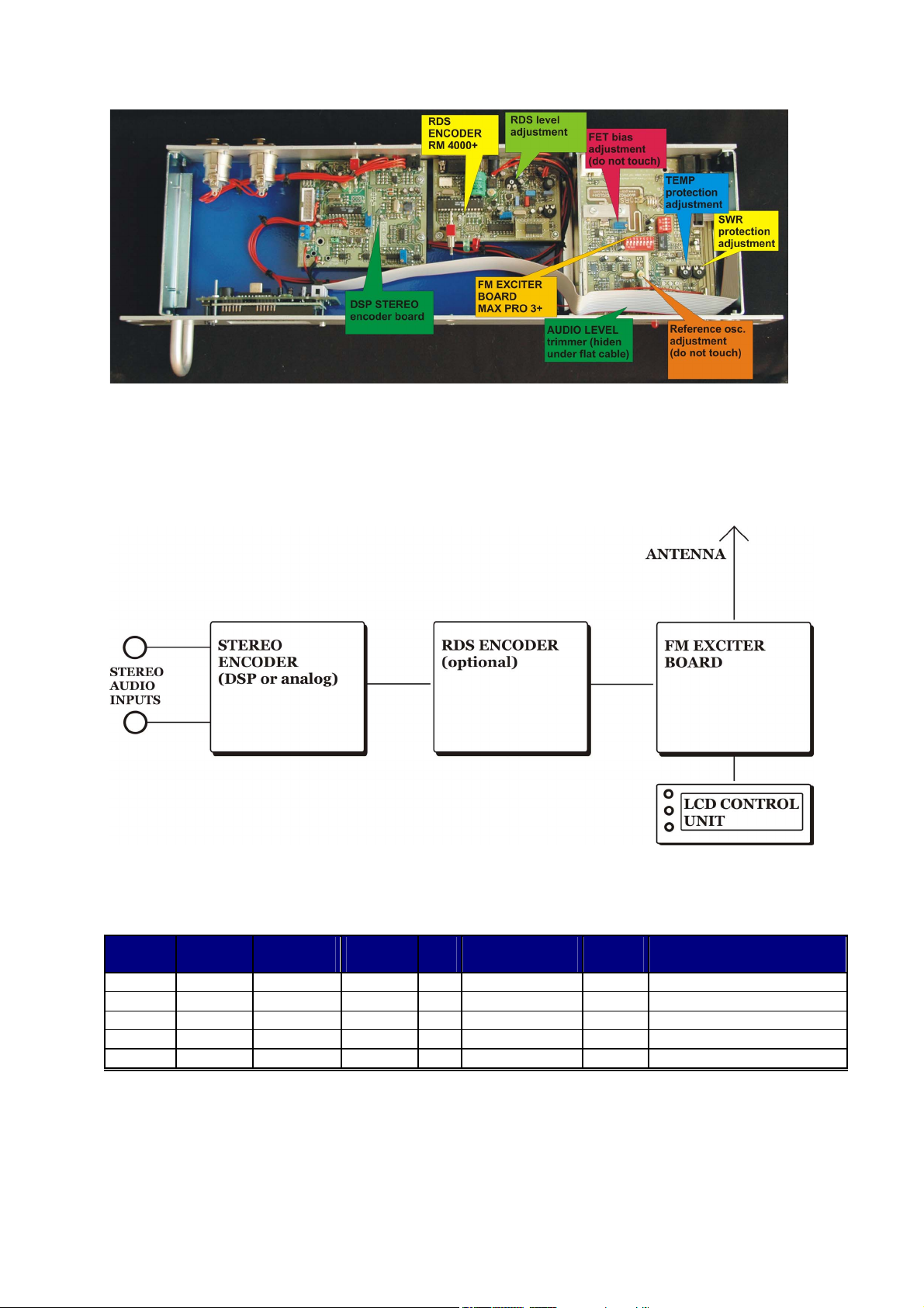
Inside the unit
Internal configuration depends on the model you purchased, but is generally similar in all four models. Separate
extensive manuals for all of the built-in components are available on our website. We have a section in our forum
dedicated to all the manuals and you can discuss each of the manuals with other forum members:
http://www.pcs-electronics.com/phpBB2/viewforum.php?f=33
Schematic diagram
These are the basic building blocks of this (and other) transmitters. Note that RDS encoder is optional and only
available in models with RDS capability. Similarly DSP encoder is only available in DSP capable models.
MODEL STEREO
DSP
processor
XLR
inputs
RDS
SWR & TEMP
protection
RF
power
FULL NAME
A YES NO NO NO YES 15W typ CYBERMAXFM+ 15W (A)
B YES YES YES NO YES 15W typ CYBERMAXFM+ 15W (B)
C YES NO YES YES YES 15W typ CYBERMAXFM+ 15W (C)
D YES YES YES YES YES 15W typ CYBERMAXFM+ 15W (D)
E NO NO NO NO YES 15W typ CYBERMAXFM+ 15W (E)
Available models
There are five models available at the moment. Look at the table above to see how they compare.

4
BEFORE YOU START USING THIS TRANSMITTER...
It is a good idea not to rush things; get informed first about the various aspects of radio broadcasting. You will find
some very useful “How to” guides, answers to most common questions, a forum and tips on antennas at
http://www.pcs-electronics.com. This is generally a good place to visit before putting your unit on the air. Also,
ARRL handbook is a very valuable printed resource on the subject of radio electronics and electronics in general. It
is released yearly and is found on every engineer’s book shelf.
HERE IS LIST OF THINGS YOU NEED TO GET CYBERMAXFM+ ON THE AIR
Antenna
Preferred type of antenna is affected by several factors, but mostly by your transmitting site. In the middle of the area
you want to cover you'll need an omni-directional antenna which transmits equally in all directions, while outside
your coverage area you can beam the signal in with a directional antenna. Before going on air get a low VSWR by
adjusting the position of the antenna and any adjustable pieces. Aim for 2:1 or less. Use low power into the antenna
when tuning it up and making adjustments. If you were using full power and a bit of the antenna came off in your
hand the VSWR could be so bad as to blow the final transistor. For the same reason check the DC continuity of the
antenna with an ohmmeter before plugging it in, to be sure it's what it's meant to be, either a short circuit or an open
one, depending on the antenna type. Please note that you won’t get a reading of 50 ohms, 50 ohms is supposed to be
antenna impedance at working frequency and your ohmmeter is measuring DC resistance. For instructions regarding
construction of antennas please see our website: http://www.pcs-electronics.com (guides section - antennas).
You should realize that antenna was, is and will always be a crucial part of the system. Special care has to be taken!
Your range largely depends how good your antenna system is. It is usually a good idea to place antenna away from
your transmitter, power supply and audio system. If you cannot meet these
requirements, you could experience feedback and other RF problems. We
cannot guarantee proper operation of any transmitter/amplifier unless
suitable antenna system is used! This applies to any transmitter.
Interestingly, strong RF field can make CD players and other digital
devices go bezerk. It can make them freeze or make them function erratically (if that happens, power CD player off
and back on). Most of the modern audio gear is not RF shielded – reducing costs is unfortunately the mantra today.
This is why keeping antenna away from audio gear and mains wiring is a good idea.
Coaxial cable
Coaxial cable is an electrical cable consisting of a round, insulated conducting wire surrounded by a round,
conducting sheath, usually surrounded by a final insulating layer. The cable is designed to carry a high-frequency or
broadband signal, usually at radio frequencies. Coaxial Cabling is a two conductor closed transmission medium that
is often used for the transmission of RF energy. It yields excellent performance at high frequencies and superior EMI
control/shielding when compared to other types of copper cabling. Coaxial cabling is commonly found in broadcast
and networking systems. Most coaxial cables have a characteristic impedance of either 50 or 75 ohms. The RF
industry uses standard type-names for coaxial cables. The U.S military uses the RG-# or RG-#/U format (probably
for "radio grade, universal", but other interpretations exist).
The common RG-58 from Radio Shack is NOT the best you can do and will lower your effective power out! Use it
only for short runs. BELDEN makes terrific coax in various qualities and with very low loss (measured in
dB’s…decibels). 3 dB loss = 1/4 of your signal strength - either lost or gained. Watch out for the correct
impedance…RG-8 and RG-58 have 50 Ohms. RG-59 and RG-6 (Low Loss Version of RG-59) have 75 Ohms. Most
antennas and transmitters including ours are 50 ohm. Check our website for good coax. Don't buy more than you
need to make the long run to your antenna and don't make up a few "jumpers" to go between your exciter, VSWR
meter and your antenna as all you'll do is create higher SWR and more line losses. H-155 or H500 are good choices!
RG-142 with Teflon is recommended for wiring inside cabinets, for baluns, Wilkinson couplers and everywhere
where resistance to heat is required as insulation won’t melt during soldering or operation.
A PIECE OF WIRE OR TV
ANTENNA IS NOT A SUITABLE
ANTENNA FOR THIS STEREO
FM TRANSMITTER!

5
So what is this swr (vswr) everyone talks about?
VSWR is a measure of how well two devices are impedance matched to each other. Typical radio equipment is
designed for 50 ohm load impedance, so we usually use 50 ohm cables and build or buy antennas that are specified
for 50 ohm. While most cables have flat impedance over frequency (they measure 50 ohm at all frequencies you are
likely to use) the same is not true of the antennas. A 1.0:1 VSWR is a perfect match. That means the load impedance
is exactly 50 ohms. A 2.0:1 VSWR is obtained when the load impedance is either 25 ohms or 100 ohms.
Because most transmitters will deliver full power with a load VSWR of up to 2.0:1, this value is usually considered
the limit for acceptable operation. Many prefer to keep their VSWR below that however, but for all practical
purposes, it is unnecessary to spend time or money trying to get much below a VSWR of 1.5:1. The benefits will be
hard to measure and even harder to notice.
On the other hand, coaxial cable losses increase rapidly, for a given frequency of operation, when the antenna VSWR
exceeds 2.0:1. This can even, in some extreme cases, result in the coaxial cable burning, even when running 100 W.
Using a higher grade of cable will definitely improve things, but even high quality coaxial cable becomes very lossy
when VSWR exceeds 3.0:1 at higher HF frequencies (or VHF and higher).
BNC connector
A connector is installed at the ends of coaxial cable and connects to the transmitter and antenna. BNC is a standard
VHF RF connector for low power applications, similar to the one used for Ethernet networks. You might get it along
with your antenna. Try to find a good quality BNC connector as PC network type usually uses cheap plastic instead
of Teflon. The good ones are usually easily recognized by much higher prices. BNC to SO239 converters are
available and will make it possible to connect PL259 (CB type or UHF) connector directly. We recommend you
either stick to BNC or use male BNC to female N type adapter, UHF (SO-239) connectors are generally regarded as
of very poor quality and only suitable for CB.
Power supply
You will need a good regulated 12-15 volt, 3A regulated power supply. You can always use a lead acid car battery
and re-charge it when you are off the air. HAM or CB power supply units do the job nicely in most cases. Poor
power supply can add hum to your signal! This unit gives more output power when you run it at 15V, but we do not
recommend using more than that. This is to protect your output transistor; too much voltage can fry your output
transistor, especially if your antenna is not matched well. You can build your own power supply or get one from our
website. Try our web site for schematics, if you want to make one by yourself.
Audio source with mixer, microphone etc
You need something to drive your transmitter. This will typically be either a computer (just plug the cable into your
sound card outputs, a mixer and a variety of audio sources, such as a microphone, CD player, DAT player, tape deck,
gramophone, MP3 player etc.
USING THE CYBERMAXFM+
Basically there are three push-buttons available for the menu system, UP, DOWN and MENU. By pushing UP or
DOWN you get a shift of frequency in corresponding direction. Hold any of these keys for a few seconds and the
jumps will increase to 500 KHz. The new frequency is saved automatically. The third button (MENU) gives you an
option to set many of the DSP functions of this unit.
THINGS TO REMEMBER
Please remember to turn off the transmitter when not in use! Remember that anything you broadcast through the
transmitter can be heard by anyone tuning in to that frequency. Although it is unlikely certain weather conditions
may allow the signal to go further than your immediate listening area so please don't broadcast anything you don't
mind anyone else hearing.

6
TROUBLESHOOTING
We hope you’ll never get to this step. We all know bad things happen. But do not despair! First, CYBERMAX FM+
is reverse polarity protected so it should blow a fuse if you reverse polarity. Fuse is the first thing to check. SWR and
TEMP protection should help, too, although you should still be careful not to exceed ratings. Next check your mains
power supply and antenna, make sure they are working properly. Also make sure your coaxial cable leading to the
transmitter is not shorted or open. If you have problems that you cannot solve yourself, please see our website for
contact information and support resources in our forum. Also check troubleshooting table on the next page and report
any other problems/solutions you have encountered so we can add them to the spreadsheet.
Troubleshooting table
PROBLEM DESCRIPTION
POSSIBLE SOLUTIONS
Red LED constantly on 1. High SWR. Check SWR and adjust antenna, if needed
2. PLL is not locked. Remove audio and see if this is caused by audio. If yes,
read below for more ideas.
3. Wait a few seconds. Unit turns this LED on when changing power or
frequency just for a few seconds until VCO stabilizes. This is normal behavior.
Transmitter cutting off with high
audio
Check if this problem goes away when there is no audio. If yes, look into the
MAX PRO 3+ manual and see how to disable PLL unlock. The problem is
either that your audio exceeds max. permitted deviation or the protection is
slightly too sensitive.
Audio too quiet If this is DSP unit, set left and right channel gain to a higher value.
Audio too quiet Open the top lid and open modulation trimmer on MAX PRO 3+ board a little
bit.
Audio still too quiet Look into the MAX PRO 3+ manual, a section there explains how to increase
audio level.
Unit does not lock on frequency
above 102-107MHz
What is your mains power supply voltage? It should be more than 12V (13.8V)
or 15V for maximum power output!
Output power less than expected Is your supply voltage less than 15V? Your output power will be substantially
reduced at 12V!
Output power less than expected If unit is overheating it will start reducing output power, Make sure it is
sufficiently cooled!
Output power less than expected Units can have slightly reduced output power at the band edges around 88 and
108 MHz. You can improve performance by tweaking coils a little bit.

7
MENU SYSTEM
The UP and DOWN keys are used to change parameter value. In normal mode the LCD simply shows the frequency
and power. Menu key can be used to enter the menu mode, repeatedly pressing this key brings up the following
menus: POWER, TREBLE, BASS, COMPRESSION, THRESHOLD, ATTACK, DECAY, INTEGRATION
INTERVAL, FIRMWARE VERSION, PLL STEP, LEFT CHANNEL GAIN, RIGHT CHANNEL GAIN, RF
EQUILIZER, CONTRAST AND STEREO MODE. Pressing the UP or DOWN key selects the desired parameter
and allows you to modify its value. Another press on the MENU key and you’re back to normal mode.
CYBER MAX FM+ automatically detects DSP processor and enables or disables appropriate control elements in
menu system. This means that while you can view the parameters and change them, they won’t actually change the
way your transmitter operates unless you are using a DSP-capable model.
Following is a description of the menu system:
PLL STEP
Transmitter frequency can normally be adjusted in smallest steps of 6.25KHz or larger steps of 12.5KHZ, 25KHz,
50KHz or 100KHz. We recommend you to select 100KHz as this lets you change frequency very fast. However, you
can enter this menu and select a PLL step of 6.25KHz for example and take advantage of these small steps. If you
need a smaller frequency step, adjust the trimmer in the PLL section of the transmitter to slightly move frequency.
POWER
This setting allows you to set output power of CYBERMAX FM+. Select desired power with the UP/DOWN keys
and press MENU key to exit the menu system and return to normal operation. Selected power is continuously
displayed on the LCD.
TREBLE and BASS
This option allows you to set the amount of TREBLE and BASS for your audio. Recommended values are marked
with (D). Only available in DSP model.
Setting the TREBLE and BASS
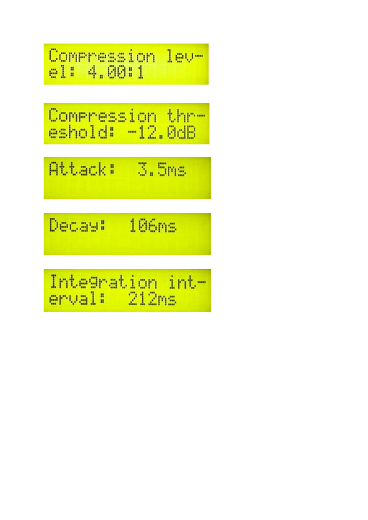
COMPRESSOR SETTINGS (ONLY DSP MODELS)
A number of MENU settings control the operation of the compressor. Lets assume that the audio signal enters the
transmitter at some low level. Compressor does nothing to the signal until at one point as the input signal increases
the signal reaches the compression threshold. Digital signal processor starts compressing the signal beyond that
point. The higher the compression ratio the higher the compression. For example, compression ratio of 1:∞would in
effect be a limiter.
8
Setting the compression level
Setting the compression threshold
Setting the attack time, this is the time between the signal rise and the actual response of the compressor
Setting the decay time, this is the time the compressor needs to respond to a decrease of the signal
Setting the integration interval, this is the time the DSP extracts the samples
Integration interval determines the energy needed to trip the compressor. In layman’s terms it determines how long
the audio needs to be loud for the compressor to respond by reducing the gain. This is not to be confused with attack
time. Attack time of 50ms means the compressor will respond in 50ms after the signal spike is detected, regardless of
duration of that spike, even if it is just a very short event. With longer integration interval, on the other hand,
compressor only responds if a substantial number of spikes is detected (meaning more signal energy).
PRE-EMPHASIS
Pre-emphasis is selected with a jumper. It should be set to either 50uS (standard for EU and most of the world) or
75uS (United states and Canada). There are two jumpers, correct position is marked on the stereo encoder board.
This is already done in the factory for you so do not change it unless you know what you are doing.
RF EQUILIZER
This is a new revolutionary setting that lets you control how your transmitter rolls off at the band edges. Several
settings are available and are represented by a graphic.
Default setting does not try to correct or increase power output at band edges. Additional settings give a slight power
boost at the band edges around 88 and 108MHz or at the upper or lower band edge only, helping flatten-out the
frequency response of many RF amplifiers which tend to have lower output power and gain at the band edges.

9
The four available settings should cover any situation you are likely to encounter, whatever your amplifier’s attitude
might be. We recommend that you keep the default (D) setting unless you know why you need to change it.
RF EQ selection
FIRMWARE
This option allows you to display transmitter firmware version and date.
Firmware version
LCD CONTRAST
Select for the best visibility. Contrast is slightly affected by ambient temperature and you can adapt it to your needs
here.
Changing contrast
LEFT AND RIGHT CHANNEL GAIN (ONLY DSP MODELS)
This option allows you to precisely adjust the input sensitivity of both audio channels. This is very useful when your
audio source has either too high or too low output level.
Changing right input channel gain
MONO/STEREO MODE SELECTION (ONLY DSP MODELS)
You can set your stereo encoder to MONO or STEREO here.
Changing mode of operation

10
USING THE CYBERMAX FM+ (WIRING)
Wiring CYBERMAX FM+ is easy:
- Connect dummy load (if you have one) or antenna to the BNC antenna connector
- Connect audio source to the audio inputs
- Connect power supply to the power jack (center is positive)
USING THE CYBERMAXFM+ (POWER-UP PROCEDURE)
The proper procedure for using the CYBERMAX FM+ is as follows:
- Wire everything as described above. If you have SWR/POWER meter, wire that one as well between transmitter
and antenna.
- Power-up the transmitter and immediately set power to zero with the up/down/menu keys, set frequency and than
set power to about 50%.
- If you have SWR/power meter check whether everything is working as expected. Check audio as well.
- Now try to increase power to 100% making sure everything is in order.
ABOUT THIS MANUAL
If you uncovered an error or wish to propose an improvement to this manual, check out our forum. We have a section
dedicated to all manuals here and you can discuss each manual with other forum members:
http://www.pcs-electronics.com/phpBB2/viewforum.php?f=33
THANK YOU FOR PURCHASING OUR CYBERMAX FM+ TRANSMITTER!
We hope you will enjoy it as much as we do and remember to tell your friends about it. Please feel free to leave your
comments at our website or post your experience in our forum.
From all of us we wish you happy broadcasting!
PCS Electronics team
www.pcs-electronics.com
APPENDIX A: IMPROVEMENT TIPS
Think about purchasing SWR meter to tune and align your antenna. A good antenna system is extremely important
and can make up for a lot of power. For a suitable SWR meter and other useful items check under transmitter
accessories: http://www.pcs-electronics.com
If you can’t get much range with your homebrew antenna, have a look at ours, some of them are priced so low its not
really worth the trouble: http://www.pcs-electronics.com
Still not enough range? Well, how about a 150W or 300W amplifier? http://www.pcs-electronics.com
So, do you think you can handle it? We think you sure can!
11
IMPORTANT NOTICE!
Please remember to turn off the transmitter/amplifier when not in use! Remember that anything you broadcast through the transmitter can be
heard by anyone tuning in to that frequency. Although it is unlikely certain weather conditions may allow the signal to go further than your
immediate listening area so please don't broadcast anything you don't mind anyone else hearing.
WARRANTY AND SERVICING!
Within one (1) year of receiving your order, if any product proves to be defective; please contact us via e-mail or our feedback form. Please DO
NOT ship the product back to us without contacting us first and receiving return instructions. After we receive the defective merchandise, we will
test it if need be, and we will ship back to you a non-defective replacement product. Please note that this doesn't cover final RF transistor as it can
be damaged by using defective or poorly matched antenna. An exception is as well any mishandling or abuse by the customer. If the product is
defective, you will receive a replacement. If you choose to return the defective item, rather than replace it, we will charge a 20% restocking fee
and your original shipping and handling charges will not be refunded. The return of the product is at your expense. We believe that this is a fair
policy because lower overhead results in lower prices for all of our customers.
LEGAL INFO & FINE PRINT
It may be illegal to operate this device in your county. Please consult local authorities before using our products!
PCS Elektronik d.o.o. is not responsible for any damage to your PC arising from use of this product and will not be held responsible for any
violation of local laws pertaining to the use of this product. It is entirely your responsibility that you make sure you operate in accordance with
local laws and/or regulations.
LIMITATION OF LIABILITY
To the law, in no event shall PCS Elektronik d.o.o. or its suppliers be liable for any special, incidental, indirect, or consequential damages
whatsoever (including, without limitation, damages for loss of business profits, business interruption, loss of business information, or any other
pecuniary loss) arising out of the use of or inability to use the PRODUCT, even if PCS Elektronik d.o.o. has been advised of the possibility of
such damages. In any case, PCS Elektronik d.o.o.´s entire liability under any provision of this agreement shall be limited to the greater of the
amount actually paid by you for the PRODUCT or U.S. $5.00; because some states and jurisdictions do not allow the exclusion or limitation of
liability, the above limitation may not apply to you.
ALSO AVAILABLE FROM PCS ELECTRONICS
We also carry a big range of:
- FM transmitters in assembled and KIT form
- AM transmitters with extremely clear modulation (PWM design)
- Various accessories for professional and hobby FM radio stations
- A large assortment of hard to obtain RF components (RF transistors; MRF, 2SC, coils, silver plated wire, coaxial
cable, capacitors, quartz crystals and many others)
- PC based FM transmitters (PCI MAX pc based FM transmitter turns your PC into a radio station)
- A large number of beginner’s guides to get you started
- Small TV transmitters
- A large selection of free schematics is as well available at our website.
Table of contents
Other PCS Electronics Transmitter manuals


Popular Transmitter manuals by other brands

Wilcoxon
Wilcoxon iT150 Series Installation and operating manual

Emerson
Emerson Rosemount X-STREAM O2 Transmitter instruction manual

Extron electronics
Extron electronics DTP2 T 202 FB user guide

Telemotive
Telemotive 10K JLTX user manual

Kramer
Kramer TP-205A user manual

Landmark Audio Technologies
Landmark Audio Technologies PLS Installation and user information


