SMAR TT302 Manual


Specifications and information are subject to change without notice.
May/99
BRAZIL
Smar Equipamentos Ind. Ltda.
Av. Dr. Antonio Furlan Jr., 1028
Sertãozinho SP 14160-000
Tel.: +55 16 645-6455
Fax: +55 16 645-6450
CHINA
Smar China Corp.
3 Baishiqiao Road, Suite 30233
Beijing 100873, P.R.C.
Tel.: +86 10 6849-8643
Fax: +86 10 6849-9549
FRANCE
Smar France S. A. R. L.
1, bld de l'Oise
Immeuble Les Maradas
95031 Cergy – Pontoise
Tel.: +33 1 30 38-3888
Fax: +33 1 30 38-4110
GERMANY
Smar GmbH
Robert-Koch-Strasse 35
D 55129 Mainz
Tel.: +49 6131 582037
Fax: +49 6131 582249
MEXICO
Smar Mexico
11, Poniente, No. 1314-1 PB
Col. Centro C. P. 72000
Ciudad de Puebla, Puebla
Tel.: +52 22 46-4386
Fax: +52 22 46-4386
NORWAY
Smar Norge A/S
Sandviksveien, 18
N-5035 Sandviken Bergen
Tel.: +47 55 13-3885
Fax: +47 55 13-3886
SINGAPORE
Smar Singapore Pte. Ltd.
315 Outram Road
#04-05, Tan Boon Liat Building
Singapore 169074
Tel.: +65 324-0182
Fax: +65 324-0183
USA
Smar International Corporation
Northwest Point Service Center
7240 Brittmoore, Suite 118
Houston, TX 77041
Tel.: +1 713 849-2021
Fax: +1 713 849-2022
Smar Laboratories Corporation
10960 Millridge North, Suite 107
Houston, TX 77070
Tel.: +1 281 807-1501
Fax: +1 281 807-1506
Smar Research Corporation
4250 Veterans Memorial Hwy.
Unit 156
Holbrook , NY 11741
Tel.: +1 516 737-3111
Fax: +1 516 737-3892

Index
III
Table of Contents
TABLE OF CONTENTS.................................................................................III
INDEX OF FIGURES .................................................................................... IV
INDEX OF TABLES ...................................................................................... IV
INTRODUCTION ........................................................................................... V
INSTALLATION ...........................................................................................1.1
GENERAL.......................................................................................................................................1.1
MOUNTING ....................................................................................................................................1.1
NETWORK WIRING .......................................................................................................................1.2
BUS TOPOLOGY AND NETWORK CONFIGURATION ................................................................ 1.4
OPERATION................................................................................................2.1
FUNCTIONAL DESCRIPTION – HARDWARE...............................................................................2.1
TEMPERATURE SENSOR.............................................................................................................2.3
CONFIGURATION.......................................................................................3.1
TRANDUCER BLOCK ....................................................................................................................3.1
HOW CONFIGURE A TRANSDUCER BLOCK ..............................................................................3.1
SENSOR TRANSDUCER NUMBER ..............................................................................................3.1
SENSOR WIRING ..........................................................................................................................3.2
JUMPER ONFIGURATION.............................................................................................................3.2
SENSOR CONFIGURATION .........................................................................................................3.3
HOW TO CONNECT TWO SENSORS TO TT302 .........................................................................3.5
COMPENSATION OF LEAD RESISTANCE FOR RTD or Ohm.....................................................3.6
COMPENSATION OF LEAD RESISTANCE FOR RTD or Ohm Double Sensors ..........................3.6
CALIBRATION IN TT302 BY THE USER .......................................................................................3.6
CHANGING UNITS IN TEMPERATURE SENSORS......................................................................3.6
TRANSDUCER DISPLAY – CONFIGURATION.............................................................................3.7
DISPLAY TRANSDUCER BLOCK..................................................................................................3.7
DEFINITION OF PARAMETERS AND VALUES ............................................................................3.8
PROGRAMMING USING LOCAL ADJUSTMENT........................................................................3.11
LOCAL PROGRAMMING TREE...................................................................................................3.11
MAINTENCE PROCEDURES......................................................................4.1
TOUBLESANTING..........................................................................................................................4.1
DISASSEMBLY PROCEDURE.......................................................................................................4.2
REASSEMBLY PROCEDURE........................................................................................................4.2
INTERCHANGEABILITY ................................................................................................................4.3
RETURNING MATERIALS .............................................................................................................4.3
TECHNICAL CHARACTERISTICS..............................................................5.1
FUNCIONAL SPECIFICATIONS ....................................................................................................5.1
PERFORMANCE SPECIFICATIONS .............................................................................................5.2
PHYSICAL SPECIFICATIONS .......................................................................................................5.2

TT302 – Fieldbus Temperature Transmitter
IV
Index of Figures
FIGURE 1.1 – COVER LOCKING ........................................................................................................1.2
FIGURE 1.2 – GROUND TERMINALS.................................................................................................1.2
FIGURE 1.3 – DIMENSIONAL DRAWING AND MOUNTING POSITIONS..........................................1.3
FIGURE 1.4 – BUS TOPOLOGY..........................................................................................................1.4
FIGURE 1.5 – TREE TOPOLOGY .......................................................................................................1.5
FIGURE 2.1 – TT302 BLOCK DIAGRAM.............................................................................................2.1
FIGURE 2.2 – LCD INDICATOR ..........................................................................................................2.2
FIGURE 2.3 – TWO-WIRE CONNECTION ..........................................................................................2.4
FIGURE 2.4 – TREE – WIRE CONNECTION ...................................................................................... 2.4
FIGURE 2.5 – FOUR WIRE CONNECTION ........................................................................................2.5
FIGURE 2.6 – DIFFERENTIAL OR DUAL CONNECTION...................................................................2.5
FIGURE 3.1 – SENSOR WIRING ........................................................................................................3.2
FIGURE 3.2 – TEMPERATURE CALIBRATION – TT302....................................................................3.3
FIGURE 3.3 – TEMPERATURE CALIBRATION – TT302....................................................................3.3
FIGURE 3.4 – TEMPERATURE CALIBRATION – TT302....................................................................3.4
FIGURE 3.5 – TEMPERATURE CALIBRATION – TT302....................................................................3.5
FIGURE 3.6 – CREATING TRANSDUCER AND FUNCTION BLOCKS ..............................................3.7
FIGURE 3.7 – PARAMETERS FOR LOCAL ADJUSTMENT CONFIGURATION ................................3.9
FIGURE 3.8 – PARAMETERS FOR LOCAL ADJUSTMENT CONFIGURATION ................................3.9
FIGURE 3.9 – PARAMETERS FOR LOCAL ADJUSTMENT CONFIGURATION ..............................3.10
FIGURE 3.10 – PARAMETERS FOR LOCAL ADJUSTMENT CONFIGURATION ............................3.10
FIGURE 3.11 – PARAMETERS FOR LOCAL ADJUSTMENT CONFIGURATION ............................3.11
FIGURE 3.12 – STEP 1 – TT302 .......................................................................................................3.11
FIGURE 3.13 – STEP 2 – TT302 .......................................................................................................3.12
FIGURE 3.14 – STEP 3 – TT302 .......................................................................................................3.12
FIGURE 3.15 – STEP 4 – TT302 .......................................................................................................3.12
FIGURE 3.16 – STEP 5 – TT302 .......................................................................................................3.13
FIGURE 3.17 – STEP 6 – TT302 .......................................................................................................3.13
FIGURE 3.18 – STEP 7 – TT302 .......................................................................................................3.13
FIGURE 4.1 – FOUR POSSIBLE POSITION OF THE DISPLAY.........................................................4.2
FIGURE 4.1 – EXPLODED VIEW ........................................................................................................4.3
Index of Tables
TABLE 3.1 – SENSOR TYPE TABLE ..................................................................................................3.4
TABLE 3.2 – TYPE OF CONNECTION TABLE ...................................................................................3.5
TABLE 3.3 – UNIT TABLE ...................................................................................................................3.6
TABLE 4.1 – MESSAGES OF ERRORS AND POTENTIAL CAUSE ...................................................4.1

Introduction
V
Introduction
The TT302 is from the first generation of FIELDBUS devices. It is a transmitter mainly
intended for measurement of temperature using RTDs or thermocouples, but can also
accept other sensors with resistance or mV output such as: pyrometers, load cells,
resistance position indicators, etc. The digital technology used in the TT302 enables a
single model to accept several types of sensors, an easy interface between the field and
the control room and several others features that considerably reduces the installation,
operation and maintenance costs.
FIELDBUS is not only a replacement for 4-20 mA or intelligent/smart transmitter
protocols. It contains much more. FIELDBUS is a complete system enabling distribution
of the control function to equipment in the field.
Some advantages of bi-directional digital communications are known from existing smart
transmitter protocols: higher accuracy, multivariable access, remote configuration and
diagnostics and multi-dropping of several devices on a single pair of wires. These
protocols were not intended to transfer control data, but maintain information. Therefore
they were slow and not efficient enough to be used.
The main requirements for Fieldbus were to overcome these problems. Closed loop
control with performance like a 4-20 mA system requires higher speed. Since higher
speed means higher power consumption, this clashes with the need for intrinsic safety.
Therefore a moderately high communication speed was selected, and the system was
designed to have minimum communication overhead. Using scheduling, the system
controls the variable sampling, the algorithm execution and the communication to
optimize the usage of the network, thus achieving high closed loop performance.
Using Fieldbus technology, with its capability to interconnect several devices, very large
control schemes can be constructed. In order to be user friendly, the function block
concept was introduced (users of SMAR CD600 should be familiar with this, since it was
implemented several years ago). The user may now easily build and overview complex
control strategies. Another advantage is adding flexibility, the control strategy may be
edited without having to rewire or change any hardware.
Now, thanks to Fieldbus, the transmitter accepts two channels, i.e., two measurements.
This reduces the cost per channel. Other function blocks are also available. They allow
flexibility in control strategy implementation.
The need for Fieldbus implementation in small as well as large systems was considered
when developing the entire 302 line of Fieldbus devices. They have the common features
of being able to act as a master on the network.
Get the best result of the TT302 by carefully reading these instructions.

TT302 – Fieldbus Temperature Transmitter
VI
WARNING
This Manual is compatible with version 3.XX, where 3 denote
software version and XX software release. The indication 3.XX
means that this manual is compatible with any release of
software version 3.

Section 1
1-1
Installation
General
The overall accuracy of temperature and other measurements depends on several
variables. Although the transmitter has an outstanding performance, proper installation is
essential in order to maximize its performance.
Among all factors which may affect transmitter accuracy, environmental conditions are
the most difficult to control. There are, however, ways of reducing the effects of
temperature, humidity and vibration.
Locating the transmitter in areas protected from extreme environmental changes can
minimize temperature fluctuation effects.
In warm environments, the transmitter should be installed in such a way as to avoid, as
much as possible, direct exposure to the sun. Installation close to lines and vessels
subjected to high temperatures should also be avoided. For temperature measurements,
sensors with cooling-neck can be used or the sensor can be mounted separately from the
transmitter housing.
Use of sunshades or heat shields to protect the transmitter from external heat sources
should be considered.
Humidity is fatal for electronic circuits. In areas subjected to high relative humidity, the O-
rings for the electronic housing covers must be correctly placed and the covers must be
completely closed by tightening them by hand until you feel the O-rings being
compressed. Do not use tools to close the covers. Removal of the electronics cover in the
field should be reduced to the minimum necessary, since each time it is removed, the
circuits are exposed to humidity. The electronic circuit is protected by a humidity proof
coating, but frequent exposure to humidity may affect the protection provided. It is also
important to keep the covers tightened in place. Every time they are removed, the threads
are exposed to corrosion, as painting cannot protect these parts. Code-approved sealing
methods should be employed on conduit entering the transmitter.
Connecting the sensor as close to the transmitter as possible and using proper wires
(See Section 2 - Operation), can decrease measurement error.
Mounting
The transmitter may be mounted in two basic ways:
Separated from the sensor, using optional mounting brackets.
Mounted on the sensor assembly.
It can be mounted in several different positions using the bracket, as shown in Figure 1.3
- Dimensional Drawing and Mounting Positions. As shown in Figure 1.3 - Dimensional
Drawing and Mounting Positions one of the conduit inlets for electrical connection is used
to mount the sensor integral to the temperature transmitter.
For better visibility, the digital display may be rotated in steps of 90°. (See Figure 4.1 -
Four Possible Positions of the Display).
TT302 – Fieldbus Temperature Transmitter
1-2
Network Wiring
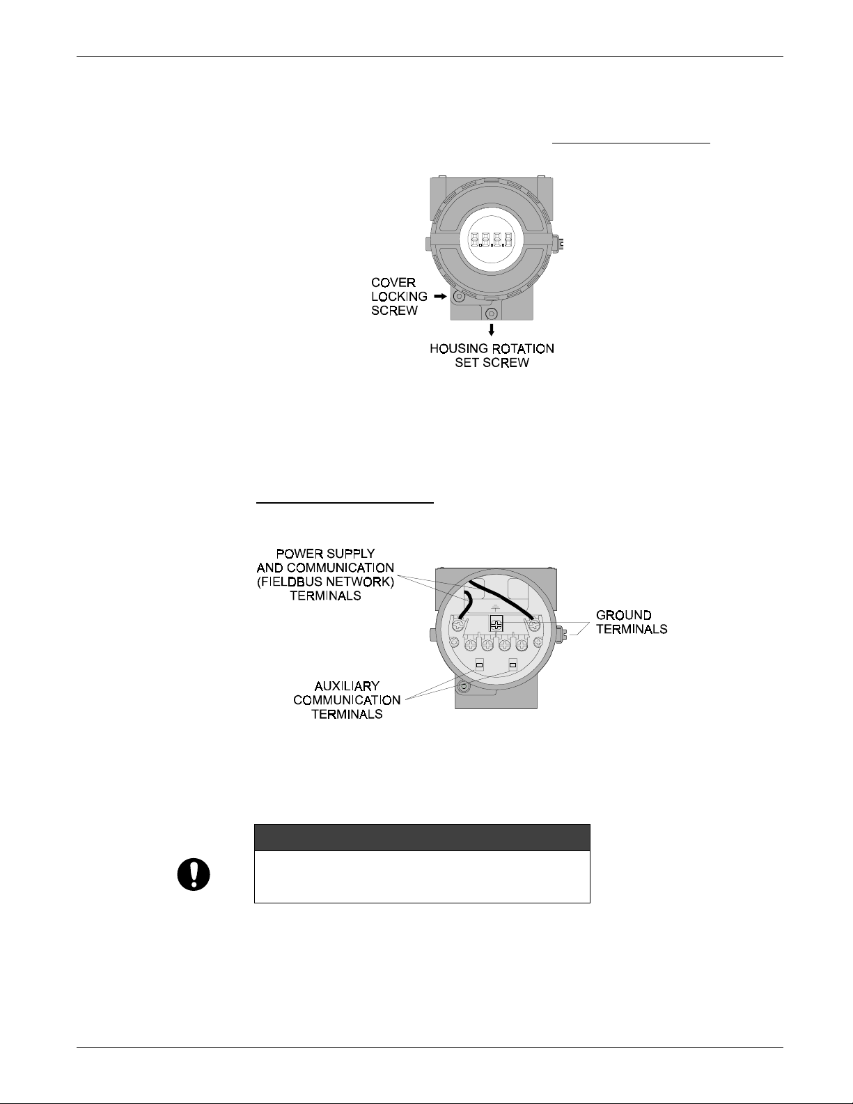
Access the terminal block by removing the Electrical Connection Cover. This cover can
be locked closed by the cover locking screw (See Figure 1.1 - Cover Locking).To release
the cover, rotate the locking screw clockwise.
Figure 1.1 - Cover Locking
Cable access to wiring connections are obtained by one of the two conduit outlets.
Conduit threads should be sealed by means of code-approved sealing methods. The
unused outlet connection should be plugged accordingly.
The wiring block has screws on which fork or ring type terminals can be fastened. (See
Figure 1.2 - Ground Terminals).
Figure 1.2 - Ground Terminals
For convenience, there are three ground terminals: one inside the cover and two
externally, located close to the conduit entries.
WARNING
Do not connect the Fieldbus network wires to the sensor
terminals. (Terminals 1, 2, 3 and 4).
TT2EM102.CDR
TT2EM101.CDR

Installation
1-3
Figure 1.3 - Dimensional Drawing and Mounting Positions
The TT302 uses the 31.25-kbit/s, voltage mode option for the physical signaling. All other
devices on the same bus must use the same signaling. All devices are connected in
parallel along the same pair of wires.
Various types of Fieldbus devices may be connected on the same bus. The TT302 is
powered via the bus. The limit for such devices is 16 for one bus for non-intrinsically safe
requirement.
In hazardous areas, the number of devices may be limited to 6 devices by intrinsically
safe restrictions.
The TT302 is protected against reverse polarity, and can withstand ±35 VDC without
damage.
Use of twisted pair cables is recommended. It is also recommended to ground shield of
shielded cables at one end only. The non-grounded end must be carefully isolated.
NOTE
Please refer to the General Installation, Operation and Maintenance
Manual for more details.
TT2EM103.CDR

TT302 – Fieldbus Temperature Transmitter
1-4
Bus Topology and Network Configuration
WARNING
HAZARDOUS AREAS
In hazardous zones with explosion proof requirements the
covers must be tightened with at least 7 turns. In order to avoid
moisture or corrosive gases, hand tighten the covers until the O-
rings are compressed. Lock the covers closed with the locking
screw.
In hazardous zones with intrinsically safe or non incendive
requirements, the circuit entity parameters and applicable
installation procedures must be observed.
Cable access to wiring connections is obtained by the two
conduit outlets. Conduit threads should be sealed by means of
code-approved sealing methods. The unused outlet connection
should be plugged and sealed accordingly.
Should other certifications be necessary, refer to the certification
or specific standard for installation limitations.
The connection of couplers should be kept at less than 15 per 250 m.
Figure 1.4 - Bus Topology
TT2EM104.CDR

Installation
1-5
Figure 1.5 - Tree Topology
TT2EM105.CDR

TT302 – Fieldbus Temperature Transmitter
1-6
Section 2
2-1
Operation
The TT302 accepts signals from mV generators such as thermocouples or resistive
sensors such as RTDs. The criterion is that the signal is within the range of the input. For
mV, the range is -50 to 500 mV and for resistance, 0-2000 Ohm.
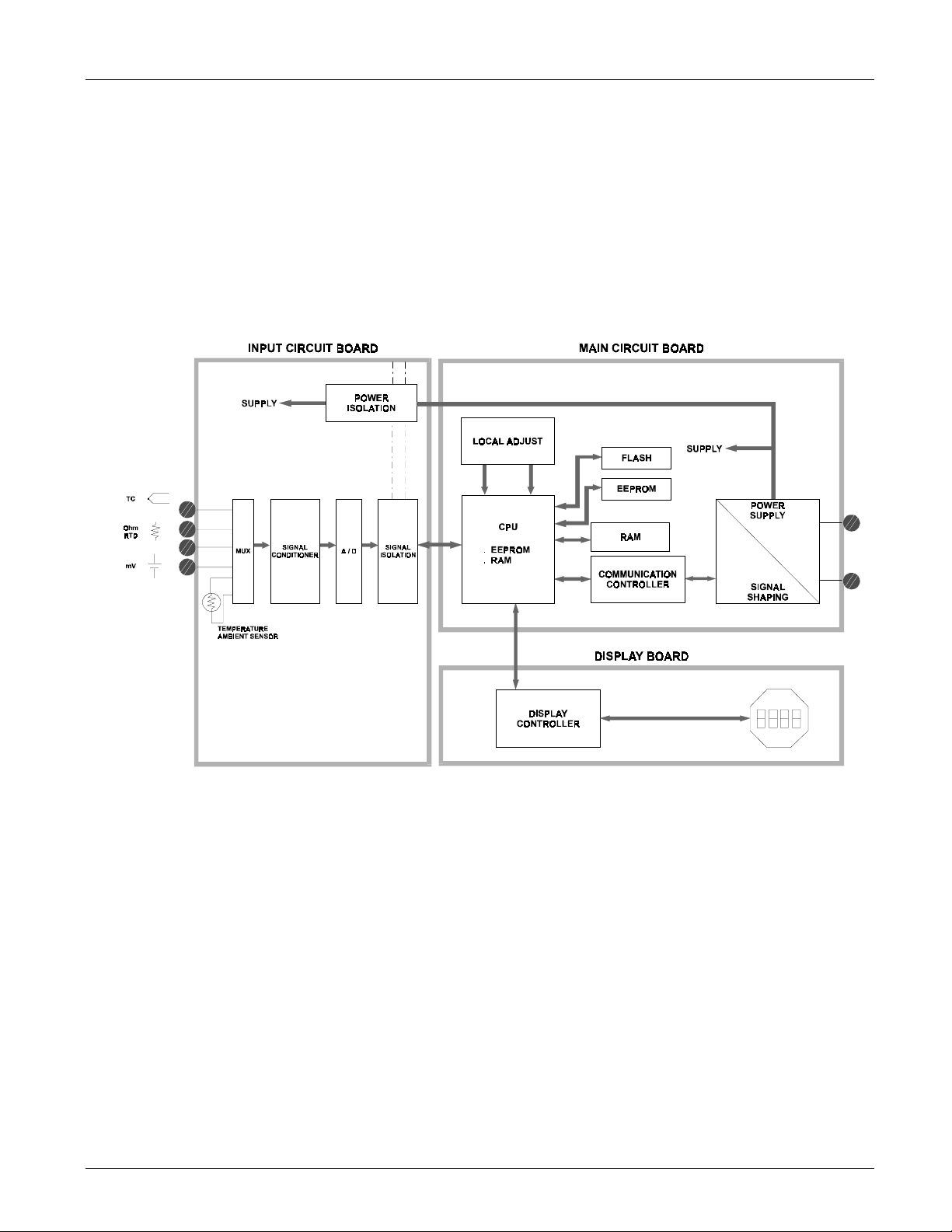
Functional Description - Hardware
The function of each block is described below.
Figure 2.1 - TT302 Block Diagram
MUX Multiplexer
The MUX multiplexes the sensor terminals to the signal conditioning section ensuring that
the voltages are measured between the correct terminals.
Signal Conditioner
Its function is to apply the correct gain to the input signals to make them suit the A/D -
converter.
A/D Converter
The A/D converts the input signal to a digital format for the CPU.
Signal Isolation
Its function is to isolate the control and data signal between the input and the CPU.
TT2EM201.CDR

TT302 – Fieldbus Temperature Transmitter
2-2
(CPU) Central Processing Unit, RAM, PROM and EEPROM
The CPU is the intelligent portion of the transmitter, being responsible for the
management and operation of measurement, block execution, self-diagnostics and
communication. The program is stored in a PROM. For temporary storage of data there is
a RAM. The data in the RAM is lost if the power is switched off. However there is a
nonvolatile EEPROM where data that must be retained is stored. Examples, of such data
are trim, calibration, block configuration and identification data.
Communication Controller
It monitors line activity, modulates and demodulates communication signals and inserts
and deletes start and end delimiters.
Power Supply
Takes power of the loop-line to power the transmitter circuitry.
Power Isolation
Just like the signals to and from the input section, the power to the input section must be
isolated. Isolation is achieved by converting the DC supply into a high frequency AC
supply and galvanically separating it using a transformer.
Display Controller
Receives data from the CPU informing which segments of the Liquid Crystal Display,
should be turned on.
Local Adjustment
There are two switches that are magnetically activated. They can be activated by the
magnetic tool without mechanical or electrical contact.
Figure 2.2 - LCD Indicator
TT2EM202.CDR

Operation
2-3
Temperature Sensors
The TT302, as previously explained, accepts several types of sensors. The TT302 is
specially designed for temperature measurement using thermocouples or Resistive
Temperature Detectors (RTDs).
Some basic concepts about these sensors are presented below.
Thermocouples
Thermocouples are constructed with two wires made from different metals or alloys
joined at one end, called measuring junction or "hot junction". The measuring junction
should be placed at the point of measurement. The other end of the thermocouple is
open and connected to the temperature transmitter. This point is called reference junction
or cold junction.
For most applications, the Seebeck effect is sufficient to explain thermocouple behavior
as following:
How the Thermocouple Works (Seebeck Effect)
When there is a temperature difference along a metal wire, a small electric potential,
unique to every alloy, will occur. This phenomenon is called Seebeck effect. When two
wires of dissimilar metals are joined at one end, and left open at the other, a temperature
difference between the two ends will result in a voltage since the potentials generated by
the dissimilar materials are different and do not cancel each other out. Now, two
important things must be noted. First: the voltage generated by the thermocouple is
proportional to the difference between the measuring-junction and the cold junction
temperatures. Therefore the temperature at the reference junction must be added to the
temperature derived from the thermocouple output, in order to find the temperature
measured. This is called cold junction compensation, and is done automatically by the
TT302, which has a temperature sensor at the sensor terminals for this purpose.
Secondly, if the thermocouple wires are not used, all the way to the terminals of the
transmitter (e.g., copper wire is used from sensor-head or marshaling box) will form new
junctions with additional Seebeck effects. It will be created and ruin the measurement in
most cases, since the cold-junction compensation will be done at the wrong point.
NOTE
Use thermocouple wires or appropriate extension wires all the way
from sensor to transmitter.
The relation between the measuring junction temperature and the generated mili-voltage
is tabulated in thermocouple calibration tables for standardized thermocouple types, the
reference temperature being 0°C.
Standardized thermocouples that are commercially used, whose tables are stored in the
memory of the TT302, are the following:
NBS (B, E, J, K, N, R, S & T)
DIN (L & U)
Resistive Temperature Detectors (RTDs)
Resistance Temperature Detectors, most commonly known as RTD’s, are based on the
principle that the resistance of metal increases as its temperature increases.
Standardized RTDs, whose tables are stored in the memory of the TT302, are the
following:
JIS [1604-81] (Pt50 & Pt100)
IEC, DIN, JIS [1604-89] (Pt50, Pt100 & Pt500)
GE (Cu10)
DIN (Ni120)

TT302 – Fieldbus Temperature Transmitter
2-4
For correct measurement of RTD temperature, it is necessary to eliminate the effect of
the resistance of the wires connecting the sensor to the measuring circuit. In some
industrial applications, these wires may be hundreds of meters long. This is particularly
important at locations where the ambient temperature changes constantly.
The TT302 permits a 2-wire connection that may cause measuring errors, depending on
the length of connection wires and on the temperature to which they are exposed. (See
Figure 2.3 - Two-Wire Connection).
In a 2-wire connection, the voltage V2 is proportional to the RTD resistance plus the
resistance of the wires.
V2 = [RTD + 2 x R] x I
Figure 2.3 - Two-Wire Connection
In order to avoid the resistance effect of the connection wires, it is recommended to use a
3-wire connection (See Figure 2.4 - Three – Wire Connection) or a 4-wire connection
(See Figure 2.5 - Four - Wire Connection).
In a 3-wire connection, terminal 3 is a high impedance input. Thus, no current flows
through that wire and no voltage drop is caused. The voltage V2-V1 is independent of the
wire resistances since they will be cancelled, and is directly proportional to the RTD
resistance alone.
V2-V1 = [RTD + R] x I - R x I = RTD x I
Figure 2.4 - Three – Wire Connection
TT2EM204.CDR
TT2EM203.CDR

Operation
2-5
In a 4-wire connection, terminals 2 and 3 are high impedance inputs. Thus, no current
flows through those wires and no voltage drop is caused. The resistance of the other two
wires is not of interest, since there is no measurement registered on them. Hence the
voltage V2 is directly proportional to the RTD resistance.
(V2 = RTD x I)
Figure 2.5 - Four - Wire Connection
A differential or dual channel connection is similar to the two-wire connection and gives
the same problem (See Figure 2.6 - Differential or Dual Connection). The resistance of
the wires will be measured and do not cancel each other out in a temperature
measurement, since linearization will affect them differently.
Figure 2.6 - Differential or Dual Connection
TT2EM206.CDR
TT2EM205.CDR

TT302 – Fieldbus Temperature Transmitter
2-6

Section 3
3-1
Configuration
One of the many advantages of Fieldbus is that device configuration is independent of
the configurator. The TT302 may be configured by a third party terminal or operator
console. Any particular configurator is therefore not addressed here.
The TT302 contains two input transducer blocks, one resource block, one display
transducer block and other function blocks.
For explanation and details of function blocks, see the “Function Blocks Manual”.
Transducer Block
Transducer block insulates function blocks from the specific I/O hardware, such as
sensors, actuators. Transducer block controls access to I/O through manufacturer
specific implementation. This permits the transducer block to execute as frequently as
necessary to obtain good data from sensors without burdening the function blocks that
uses the data. It also insulates the function block from the manufacturer specific
characteristics of certain hardware.
By accessing the hardware, the transducer block can get data from I/O or passing control
data to it. The connection between Transducer block and Function block is called
channel. These blocks can exchange data from its interface.
Normally, transducer blocks perform functions, such as linearization, characterization,
temperature compensation, control and exchange data to hardware.
How to Configure a Transducer Block
The transducer block has an algorithm, a set of contained parameters, it means, you are
not able to link these parameters to other blocks and publish the link via communication,
and a channel connecting it to a function block.
The algorithm describes the behavior of the transducer as a data transfer function
between the I/O hardware and other function block. The set of contained parameters
defines the user interface to the transducer block. They can be divided into Standard and
Manufacturer Specific.
The standard parameters will be present for such class of device, as pressure,
temperature, actuator, etc., whatever is the manufacturer. Oppositely, the manufacturers
specific ones are defined only for its manufacturer. As common manufacturer specific
parameters, we have calibration settings, material information, linearization curve, etc.
When you perform a standard routine such as calibration, you are conducted step by step
by a method. The method is generally defined as guideline to help the user to make
common tasks. The SYSCON identifies each method associated to the parameters and
enables the interface to it.
Sensor Transducer Number
The Sensor Transducer Number associates the sensor to the transducer. It can be set to
one up to two, in case of dual sensor.

TT302 – Fieldbus Temperature Transmitter
3-2
Sensor Wiring
The TT302 accepts up to two sensors and may operate in one of three modes:
Single channel single sensor measurement
Dual channel dual sensor measurement
Single channel dual sensor differential measurement.
Single channel dual sensor backup measurement.
NOTE
Avoid routing sensor wiring close to power cables or switching
equipment.
In accordance with connection and sensor types, the terminal blocks shall be wired as
shown on the figure below (See Figure 3.1 - Sensor Wiring).
Figure 3.1 - Sensor Wiring
Jumper Configuration
In order to work properly, the jumpers J1 and J3 located in the TT302 main board must
be correctly configured.
J1 is responsible to enable the AI block simulate mode.
W1 is responsable to enable the local adjustment.
TT2EM301.CDR
Other manuals for TT302
2
Table of contents
Other SMAR Transmitter manuals


Popular Transmitter manuals by other brands


DCI
DCI DigiTrak FALCON F5 Sub-k Rebar Supplement

NIVELCO
NIVELCO EchoTREK S-300 Installation and programming manual

Long Range Systems
Long Range Systems T9560 Multitouch user manual

Infinite
Infinite L-Com SRAQ-G213 manual

VARIZOOM
VARIZOOM VZ-WFF instruction manual

Stageline
Stageline TXS-862HSE instruction manual