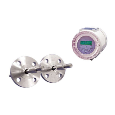
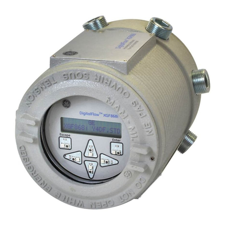
Panametrics DigitalFlow XGM868i Owner's manual


Flow
panametrics.com
Copyright 2021 Baker Hughes company.
This material contains one or more registered trademarks of Baker Hughes Company and its subsidiaries
in one or more countries. All third-party product and company names are trademarks of their respective
holders.
DigitalFlow™ XGM868i
Panametrics General-Purpose Gas Flow Transmitter (1 &
2 Channel)
Programming Manual
910-197P Rev. F
Jul 2021

ii
[no content intended for this page]

DigitalFlow™ XGM868i Programming Manual iii
Information Paragraphs
Note:
These paragraphs provide information that provides a deeper understanding of the situation, but is not
essential to the proper completion of the instructions.
IMPORTANT: These paragraphs provide information emphasizing instructions which are essential to proper setup of
the equipment. Failure to follow these instructions carefully may cause unreliable performance.
Safety Issues
Auxiliary Equipment
Local Safety Standards
The user must make sure that he operates all auxiliary equipment in accordance with local codes, standards,
regulations, or laws applicable to safety.
Working Area
WARNING! Indicates a potentially hazardous situation which can result in serious personal
injury or death, if it is not avoided.
CAUTION! Indicates a potentially hazardous situation which can result in minor or moderate
injury to personnel or damage to the equipment, if it is not avoided.
HIGH VOLTAGE! This symbol indicates the presence of high voltage. It calls your attention to
situations or operations that could be dangerous to you and other persons operating the equipment.
Read these messages and follow the instructions carefully.
WARNING! It is the responsibility of the user to make sure all local, county, state and national
codes, regulations, rules and laws related to safety and safe operating conditions
are met for each installation.
WARNING! Auxiliary equipment may have both manual and automatic modes of operation. As
equipment can move suddenly and without warning, do not enter the work cell of
this equipment during automatic operation, and do not enter the work envelope of
this equipment during manual operation. If you do, serious injury can result.

iv DigitalFlow™ XGM868i Programming Manual
Qualification of Personnel
Make sure that all personnel have manufacturer-approved training applicable to the auxiliary equipment.
Personal Safety Equipment
Make sure that operators and maintenance personnel have all safety equipment applicable to the auxiliary
equipment. Examples include safety glasses, protective headgear, safety shoes, etc.
Unauthorized Operation
Make sure that unauthorized personnel cannot gain access to the operation of the equipment.
Environmental Compliance
Waste Electrical and Electronic Equipment (WEEE) Directive
Panametrics is an active participant in Europe’s
Waste Electrical and Electronic Equipment
(WEEE) take-back
initiative, directive 2012/19/EU.
The equipment that you bought has required the extraction and use of natural resources for its production. It may
contain hazardous substances that could impact health and the environment.
In order to avoid the dissemination of those substances in our environment and to diminish the pressure on the
natural resources, we encourage you to use the appropriate take-back systems. Those systems will reuse or recycle
most of the materials of your end life equipment in a sound way.
The crossed-out wheeled bin symbol invites you to use those systems.
If you need more information on the collection, reuse and recycling systems, please contact your local or regional
waste administration.
Visit www.bakerhughesds.com/health-safetyand-environment-hse for take-back instructions and more information
about this initiative.
WARNING! Make sure that power to the auxiliary equipment is turned OFF and locked out
before you perform maintenance procedures on the equipment.

DigitalFlow™ XGM868i Programming Manual v
Contents
Chapter 1. Programming Site Data
1.1 Introduction . . . . . . . . . . . . . . . . . . . . . . . . . . . . . . . . . . . . . . . . . . . . . . . . . . . . . . . . . . . . . . . . . . . . . . . . . . . . . . . . . . . . . . . . . . . . . . . . . . . . . .1
1.2 Programming Methods . . . . . . . . . . . . . . . . . . . . . . . . . . . . . . . . . . . . . . . . . . . . . . . . . . . . . . . . . . . . . . . . . . . . . . . . . . . . . . . . . . . . . . . . . . 2
1.3 The XGM868i Enclosure Keypad . . . . . . . . . . . . . . . . . . . . . . . . . . . . . . . . . . . . . . . . . . . . . . . . . . . . . . . . . . . . . . . . . . . . . . . . . . . . . . . . . 2
1.4 Activating a Channel . . . . . . . . . . . . . . . . . . . . . . . . . . . . . . . . . . . . . . . . . . . . . . . . . . . . . . . . . . . . . . . . . . . . . . . . . . . . . . . . . . . . . . . . . . . . 4
1.5 Entering System Data for the Channel. . . . . . . . . . . . . . . . . . . . . . . . . . . . . . . . . . . . . . . . . . . . . . . . . . . . . . . . . . . . . . . . . . . . . . . . . . . 5
1.5.1 Accessing the Channelx-System Submenu . . . . . . . . . . . . . . . . . . . . . . . . . . . . . . . . . . . . . . . . . . . . . . . . . . . . . . . . . . . . . . . . . 5
1.5.2 Selecting Volumetric Units . . . . . . . . . . . . . . . . . . . . . . . . . . . . . . . . . . . . . . . . . . . . . . . . . . . . . . . . . . . . . . . . . . . . . . . . . . . . . . . . . . 5
1.5.3 Selecting Totalizer Units. . . . . . . . . . . . . . . . . . . . . . . . . . . . . . . . . . . . . . . . . . . . . . . . . . . . . . . . . . . . . . . . . . . . . . . . . . . . . . . . . . . . . 5
1.5.4 Selecting Mass Flow Units. . . . . . . . . . . . . . . . . . . . . . . . . . . . . . . . . . . . . . . . . . . . . . . . . . . . . . . . . . . . . . . . . . . . . . . . . . . . . . . . . . . 6
1.6 Entering Transducer and Pipe Parameters. . . . . . . . . . . . . . . . . . . . . . . . . . . . . . . . . . . . . . . . . . . . . . . . . . . . . . . . . . . . . . . . . . . . . . . 6
1.6.1 Special Transducers. . . . . . . . . . . . . . . . . . . . . . . . . . . . . . . . . . . . . . . . . . . . . . . . . . . . . . . . . . . . . . . . . . . . . . . . . . . . . . . . . . . . . . . . . 6
1.6.2 Pipe Data . . . . . . . . . . . . . . . . . . . . . . . . . . . . . . . . . . . . . . . . . . . . . . . . . . . . . . . . . . . . . . . . . . . . . . . . . . . . . . . . . . . . . . . . . . . . . . . . . . . 7
1.7 Entering Zero Cutoff and Setting Up Inputs . . . . . . . . . . . . . . . . . . . . . . . . . . . . . . . . . . . . . . . . . . . . . . . . . . . . . . . . . . . . . . . . . . . . . . 9
1.7.1 Zero Cutoff Value . . . . . . . . . . . . . . . . . . . . . . . . . . . . . . . . . . . . . . . . . . . . . . . . . . . . . . . . . . . . . . . . . . . . . . . . . . . . . . . . . . . . . . . . . . . . 9
1.7.2 Temperature Input . . . . . . . . . . . . . . . . . . . . . . . . . . . . . . . . . . . . . . . . . . . . . . . . . . . . . . . . . . . . . . . . . . . . . . . . . . . . . . . . . . . . . . . . . . 9
1.7.3 Base Temperature . . . . . . . . . . . . . . . . . . . . . . . . . . . . . . . . . . . . . . . . . . . . . . . . . . . . . . . . . . . . . . . . . . . . . . . . . . . . . . . . . . . . . . . . . 10
1.7.4 Pressure Input. . . . . . . . . . . . . . . . . . . . . . . . . . . . . . . . . . . . . . . . . . . . . . . . . . . . . . . . . . . . . . . . . . . . . . . . . . . . . . . . . . . . . . . . . . . . . . 10
1.7.5 Base Pressure . . . . . . . . . . . . . . . . . . . . . . . . . . . . . . . . . . . . . . . . . . . . . . . . . . . . . . . . . . . . . . . . . . . . . . . . . . . . . . . . . . . . . . . . . . . . . . 10
1.7.6 Low Pressure Switch. . . . . . . . . . . . . . . . . . . . . . . . . . . . . . . . . . . . . . . . . . . . . . . . . . . . . . . . . . . . . . . . . . . . . . . . . . . . . . . . . . . . . . . . . 11
1.8 Entering Setup Data . . . . . . . . . . . . . . . . . . . . . . . . . . . . . . . . . . . . . . . . . . . . . . . . . . . . . . . . . . . . . . . . . . . . . . . . . . . . . . . . . . . . . . . . . . . . . 11
1.8.1 Setting Transducer Signal Parameters . . . . . . . . . . . . . . . . . . . . . . . . . . . . . . . . . . . . . . . . . . . . . . . . . . . . . . . . . . . . . . . . . . . . . . 11
1.8.2 Initializing Setup Parameters - Default Setup . . . . . . . . . . . . . . . . . . . . . . . . . . . . . . . . . . . . . . . . . . . . . . . . . . . . . . . . . . . . . . 14
1.8.3 Setting Response Time - V Averaging. . . . . . . . . . . . . . . . . . . . . . . . . . . . . . . . . . . . . . . . . . . . . . . . . . . . . . . . . . . . . . . . . . . . . . 14
1.8.4 Using Advanced Features. . . . . . . . . . . . . . . . . . . . . . . . . . . . . . . . . . . . . . . . . . . . . . . . . . . . . . . . . . . . . . . . . . . . . . . . . . . . . . . . . . 15
1.9 Entering Global Data . . . . . . . . . . . . . . . . . . . . . . . . . . . . . . . . . . . . . . . . . . . . . . . . . . . . . . . . . . . . . . . . . . . . . . . . . . . . . . . . . . . . . . . . . . . .17
1.9.1 Entering Global System Data . . . . . . . . . . . . . . . . . . . . . . . . . . . . . . . . . . . . . . . . . . . . . . . . . . . . . . . . . . . . . . . . . . . . . . . . . . . . . . . 18
1.9.2 Setting Up Inputs and Outputs . . . . . . . . . . . . . . . . . . . . . . . . . . . . . . . . . . . . . . . . . . . . . . . . . . . . . . . . . . . . . . . . . . . . . . . . . . . . .20
1.9.3 Configuring the Communications Port. . . . . . . . . . . . . . . . . . . . . . . . . . . . . . . . . . . . . . . . . . . . . . . . . . . . . . . . . . . . . . . . . . . . . .31
1.9.4 Requesting Parameters Using MODBUS . . . . . . . . . . . . . . . . . . . . . . . . . . . . . . . . . . . . . . . . . . . . . . . . . . . . . . . . . . . . . . . . . . . . 33
1.9.5 Activating Security. . . . . . . . . . . . . . . . . . . . . . . . . . . . . . . . . . . . . . . . . . . . . . . . . . . . . . . . . . . . . . . . . . . . . . . . . . . . . . . . . . . . . . . . .35
1.10 Exiting the User Program. . . . . . . . . . . . . . . . . . . . . . . . . . . . . . . . . . . . . . . . . . . . . . . . . . . . . . . . . . . . . . . . . . . . . . . . . . . . . . . . . . . . . . . . 36
Chapter 2. Displaying Data
2.1 Introduction . . . . . . . . . . . . . . . . . . . . . . . . . . . . . . . . . . . . . . . . . . . . . . . . . . . . . . . . . . . . . . . . . . . . . . . . . . . . . . . . . . . . . . . . . . . . . . . . . . . . 37
2.2 Displaying Data with the LCD . . . . . . . . . . . . . . . . . . . . . . . . . . . . . . . . . . . . . . . . . . . . . . . . . . . . . . . . . . . . . . . . . . . . . . . . . . . . . . . . . . . 37
2.2.1 Adjusting LCD Contrast . . . . . . . . . . . . . . . . . . . . . . . . . . . . . . . . . . . . . . . . . . . . . . . . . . . . . . . . . . . . . . . . . . . . . . . . . . . . . . . . . . . . 37
2.2.2 Programming the LCD . . . . . . . . . . . . . . . . . . . . . . . . . . . . . . . . . . . . . . . . . . . . . . . . . . . . . . . . . . . . . . . . . . . . . . . . . . . . . . . . . . . . . 37
2.3 Displaying Data on a Computer Terminal . . . . . . . . . . . . . . . . . . . . . . . . . . . . . . . . . . . . . . . . . . . . . . . . . . . . . . . . . . . . . . . . . . . . . .39
2.3.1 Preparing for PanaView Programming . . . . . . . . . . . . . . . . . . . . . . . . . . . . . . . . . . . . . . . . . . . . . . . . . . . . . . . . . . . . . . . . . . . . .39
2.3.1 The Text Display Output . . . . . . . . . . . . . . . . . . . . . . . . . . . . . . . . . . . . . . . . . . . . . . . . . . . . . . . . . . . . . . . . . . . . . . . . . . . . . . . . . . . .40
2.3.2 The Graphing Output . . . . . . . . . . . . . . . . . . . . . . . . . . . . . . . . . . . . . . . . . . . . . . . . . . . . . . . . . . . . . . . . . . . . . . . . . . . . . . . . . . . . . .43
2.3.3 Displaying Transducer Signals . . . . . . . . . . . . . . . . . . . . . . . . . . . . . . . . . . . . . . . . . . . . . . . . . . . . . . . . . . . . . . . . . . . . . . . . . . . .45
Chapter 3. Logging Data
3.1 Introduction . . . . . . . . . . . . . . . . . . . . . . . . . . . . . . . . . . . . . . . . . . . . . . . . . . . . . . . . . . . . . . . . . . . . . . . . . . . . . . . . . . . . . . . . . . . . . . . . . . . .49
3.2 Data Logging Option Card. . . . . . . . . . . . . . . . . . . . . . . . . . . . . . . . . . . . . . . . . . . . . . . . . . . . . . . . . . . . . . . . . . . . . . . . . . . . . . . . . . . . . .49
3.3 Logging with PanaView . . . . . . . . . . . . . . . . . . . . . . . . . . . . . . . . . . . . . . . . . . . . . . . . . . . . . . . . . . . . . . . . . . . . . . . . . . . . . . . . . . . . . . . . .49
3.4 Creating Meter Logs . . . . . . . . . . . . . . . . . . . . . . . . . . . . . . . . . . . . . . . . . . . . . . . . . . . . . . . . . . . . . . . . . . . . . . . . . . . . . . . . . . . . . . . . . . . .49
3.4.1 Creating a Standard Meter Log . . . . . . . . . . . . . . . . . . . . . . . . . . . . . . . . . . . . . . . . . . . . . . . . . . . . . . . . . . . . . . . . . . . . . . . . . . . .50
3.4.2 Creating an Error Log . . . . . . . . . . . . . . . . . . . . . . . . . . . . . . . . . . . . . . . . . . . . . . . . . . . . . . . . . . . . . . . . . . . . . . . . . . . . . . . . . . . . . .52
3.5 Creating PC Logs . . . . . . . . . . . . . . . . . . . . . . . . . . . . . . . . . . . . . . . . . . . . . . . . . . . . . . . . . . . . . . . . . . . . . . . . . . . . . . . . . . . . . . . . . . . . . . .54
3.6 Viewing Meter Log Files . . . . . . . . . . . . . . . . . . . . . . . . . . . . . . . . . . . . . . . . . . . . . . . . . . . . . . . . . . . . . . . . . . . . . . . . . . . . . . . . . . . . . . . . . 57
3.7 Viewing PC Log Files . . . . . . . . . . . . . . . . . . . . . . . . . . . . . . . . . . . . . . . . . . . . . . . . . . . . . . . . . . . . . . . . . . . . . . . . . . . . . . . . . . . . . . . . . . . .59
Chapter 4. Printing Data
4.1 Data Types for Printing . . . . . . . . . . . . . . . . . . . . . . . . . . . . . . . . . . . . . . . . . . . . . . . . . . . . . . . . . . . . . . . . . . . . . . . . . . . . . . . . . . . . . . . . . 61

Contents
vi DigitalFlow™ XGM868i Programming Manual
Chapter 5. Clearing Data
5.1 Introduction . . . . . . . . . . . . . . . . . . . . . . . . . . . . . . . . . . . . . . . . . . . . . . . . . . . . . . . . . . . . . . . . . . . . . . . . . . . . . . . . . . . . . . . . . . . . . . . . . . . .63
5.2 Clearing the XGM868i’s Memory . . . . . . . . . . . . . . . . . . . . . . . . . . . . . . . . . . . . . . . . . . . . . . . . . . . . . . . . . . . . . . . . . . . . . . . . . . . . . . . .63
5.2.1 Clearing Site Data. . . . . . . . . . . . . . . . . . . . . . . . . . . . . . . . . . . . . . . . . . . . . . . . . . . . . . . . . . . . . . . . . . . . . . . . . . . . . . . . . . . . . . . . . .63
5.2.2 Clearing Log Files . . . . . . . . . . . . . . . . . . . . . . . . . . . . . . . . . . . . . . . . . . . . . . . . . . . . . . . . . . . . . . . . . . . . . . . . . . . . . . . . . . . . . . . . . .64
5.2.3 Clearing the Totalizers. . . . . . . . . . . . . . . . . . . . . . . . . . . . . . . . . . . . . . . . . . . . . . . . . . . . . . . . . . . . . . . . . . . . . . . . . . . . . . . . . . . . .65
Appendix A. Menu Maps
Appendix B. Data Records
B.1 Available Option Cards . . . . . . . . . . . . . . . . . . . . . . . . . . . . . . . . . . . . . . . . . . . . . . . . . . . . . . . . . . . . . . . . . . . . . . . . . . . . . . . . . . . . . . . . .73
B.2 Option Cards Installed . . . . . . . . . . . . . . . . . . . . . . . . . . . . . . . . . . . . . . . . . . . . . . . . . . . . . . . . . . . . . . . . . . . . . . . . . . . . . . . . . . . . . . . . . .74
B.3 Setup Data. . . . . . . . . . . . . . . . . . . . . . . . . . . . . . . . . . . . . . . . . . . . . . . . . . . . . . . . . . . . . . . . . . . . . . . . . . . . . . . . . . . . . . . . . . . . . . . . . . . . . .75
Appendix C. Programming the XGM868i Using PanaView™
C.1 Introduction . . . . . . . . . . . . . . . . . . . . . . . . . . . . . . . . . . . . . . . . . . . . . . . . . . . . . . . . . . . . . . . . . . . . . . . . . . . . . . . . . . . . . . . . . . . . . . . . . . . .79
C.2 Programming Using PanaView™. . . . . . . . . . . . . . . . . . . . . . . . . . . . . . . . . . . . . . . . . . . . . . . . . . . . . . . . . . . . . . . . . . . . . . . . . . . . . . . .79
C.2.1 Preparing for PanaView Programming. . . . . . . . . . . . . . . . . . . . . . . . . . . . . . . . . . . . . . . . . . . . . . . . . . . . . . . . . . . . . . . . . . . . .79
C.2.2 Setting Up the Communications Port. . . . . . . . . . . . . . . . . . . . . . . . . . . . . . . . . . . . . . . . . . . . . . . . . . . . . . . . . . . . . . . . . . . . . .80
C.2.3 Setting up Ethernet Communications . . . . . . . . . . . . . . . . . . . . . . . . . . . . . . . . . . . . . . . . . . . . . . . . . . . . . . . . . . . . . . . . . . . . .82
C.2.4 Modifying Ethernet Parameters . . . . . . . . . . . . . . . . . . . . . . . . . . . . . . . . . . . . . . . . . . . . . . . . . . . . . . . . . . . . . . . . . . . . . . . . . . .83
C.3 Adding the XGM868i . . . . . . . . . . . . . . . . . . . . . . . . . . . . . . . . . . . . . . . . . . . . . . . . . . . . . . . . . . . . . . . . . . . . . . . . . . . . . . . . . . . . . . . . . . . .84
C.4 Entering the User Program Using PanaView. . . . . . . . . . . . . . . . . . . . . . . . . . . . . . . . . . . . . . . . . . . . . . . . . . . . . . . . . . . . . . . . . . . . .86
C.5 Entering Data in the Channel Menu . . . . . . . . . . . . . . . . . . . . . . . . . . . . . . . . . . . . . . . . . . . . . . . . . . . . . . . . . . . . . . . . . . . . . . . . . . . . .89
C.5.1 Selecting the Channel Measurement Method . . . . . . . . . . . . . . . . . . . . . . . . . . . . . . . . . . . . . . . . . . . . . . . . . . . . . . . . . . . . .89
C.5.2 Entering Data in the Channel System Option. . . . . . . . . . . . . . . . . . . . . . . . . . . . . . . . . . . . . . . . . . . . . . . . . . . . . . . . . . . . . .90
C.5.3 Entering Pipe Parameters . . . . . . . . . . . . . . . . . . . . . . . . . . . . . . . . . . . . . . . . . . . . . . . . . . . . . . . . . . . . . . . . . . . . . . . . . . . . . . . . .92
C.5.4 Entering Input/Output Parameters . . . . . . . . . . . . . . . . . . . . . . . . . . . . . . . . . . . . . . . . . . . . . . . . . . . . . . . . . . . . . . . . . . . . . . . .94
C.5.5 Entering Setup Parameters. . . . . . . . . . . . . . . . . . . . . . . . . . . . . . . . . . . . . . . . . . . . . . . . . . . . . . . . . . . . . . . . . . . . . . . . . . . . . . . .96
C.6 Entering Data in the Global Menu . . . . . . . . . . . . . . . . . . . . . . . . . . . . . . . . . . . . . . . . . . . . . . . . . . . . . . . . . . . . . . . . . . . . . . . . . . . . . . 102
C.6.1 Entering Global-System Data. . . . . . . . . . . . . . . . . . . . . . . . . . . . . . . . . . . . . . . . . . . . . . . . . . . . . . . . . . . . . . . . . . . . . . . . . . . . . 103
C.6.2 Setting Up Inputs and Outputs . . . . . . . . . . . . . . . . . . . . . . . . . . . . . . . . . . . . . . . . . . . . . . . . . . . . . . . . . . . . . . . . . . . . . . . . . . . 105
C.6.3 Entering Communications Data. . . . . . . . . . . . . . . . . . . . . . . . . . . . . . . . . . . . . . . . . . . . . . . . . . . . . . . . . . . . . . . . . . . . . . . . . . .117
C.7 Exiting the Site Edit Menu. . . . . . . . . . . . . . . . . . . . . . . . . . . . . . . . . . . . . . . . . . . . . . . . . . . . . . . . . . . . . . . . . . . . . . . . . . . . . . . . . . . . . . . 122
C.8 Saving Site Data . . . . . . . . . . . . . . . . . . . . . . . . . . . . . . . . . . . . . . . . . . . . . . . . . . . . . . . . . . . . . . . . . . . . . . . . . . . . . . . . . . . . . . . . . . . . . . . 123
C.8.1 Saving Current Site Data to the Meter . . . . . . . . . . . . . . . . . . . . . . . . . . . . . . . . . . . . . . . . . . . . . . . . . . . . . . . . . . . . . . . . . . . . 124
C.8.2 Saving New Site Data to the XGM868i . . . . . . . . . . . . . . . . . . . . . . . . . . . . . . . . . . . . . . . . . . . . . . . . . . . . . . . . . . . . . . . . . . . . 125
C.8.3 Saving a Site to the PC . . . . . . . . . . . . . . . . . . . . . . . . . . . . . . . . . . . . . . . . . . . . . . . . . . . . . . . . . . . . . . . . . . . . . . . . . . . . . . . . . . . 125
C.8.4 Clearing a Site from the Meter . . . . . . . . . . . . . . . . . . . . . . . . . . . . . . . . . . . . . . . . . . . . . . . . . . . . . . . . . . . . . . . . . . . . . . . . . . . 126
C.8.5 Saving Site Data in Text Form . . . . . . . . . . . . . . . . . . . . . . . . . . . . . . . . . . . . . . . . . . . . . . . . . . . . . . . . . . . . . . . . . . . . . . . . . . . . 126
Appendix D. PanaView Menu Maps for the XGM868i
Appendix E. Foundation Fieldbus Communications
E.1 Introduction . . . . . . . . . . . . . . . . . . . . . . . . . . . . . . . . . . . . . . . . . . . . . . . . . . . . . . . . . . . . . . . . . . . . . . . . . . . . . . . . . . . . . . . . . . . . . . . . . . . 133
E.2 Configuration Utility Setup . . . . . . . . . . . . . . . . . . . . . . . . . . . . . . . . . . . . . . . . . . . . . . . . . . . . . . . . . . . . . . . . . . . . . . . . . . . . . . . . . . . . . 134
E.3 Selecting the Desired Measurements . . . . . . . . . . . . . . . . . . . . . . . . . . . . . . . . . . . . . . . . . . . . . . . . . . . . . . . . . . . . . . . . . . . . . . . . . . 134
E.1 Selecting Units for AI Blocks . . . . . . . . . . . . . . . . . . . . . . . . . . . . . . . . . . . . . . . . . . . . . . . . . . . . . . . . . . . . . . . . . . . . . . . . . . . . . . . . . . . . 136
E.1 Resetting Instrument Totalizers . . . . . . . . . . . . . . . . . . . . . . . . . . . . . . . . . . . . . . . . . . . . . . . . . . . . . . . . . . . . . . . . . . . . . . . . . . . . . . . . 137
E.1 Function Block Application. . . . . . . . . . . . . . . . . . . . . . . . . . . . . . . . . . . . . . . . . . . . . . . . . . . . . . . . . . . . . . . . . . . . . . . . . . . . . . . . . . . . . 138
Appendix F. Foundation Fieldbus Tables

DigitalFlow™ XGM868i Programming Manual 1
Chapter 1. Programming Site Data
1.1 Introduction
The Model XGM868i flow transmitter must be properly installed and programmed, as described in the
Startup Guide
,
before it can provide accurate flow rate measurements. After completing the installation and initial setup, use this
chapter to program the advanced features of the Model XGM868i’s
Keypad Program
.
Step-by-step programming instructions are presented in this chapter. Also, as a programming aid, a complete set of
menu maps for the XGM868i are included in Appendix A,
Menu Maps
. The specific figure numbers will be referenced
throughout this chapter, as required.
Refer to the appropriate section for a discussion of the following
Keypad Program
features.
•Channelx-ACTIV - activate one or both channels and Scroll to the desired measurement method.
•Channelx-SYSTM - enter the individual channel parameters.
•Channelx-PIPE - enter the pipe geometry and other parameters.
•Channelx-I/O - set up the inputs and outputs.
•Channelx-SETUP - set the signal limits, response times and mass flow status.
•Global-SYSTM - scroll to system units (English or metric).
•Global-I/O - set up error handling, option cards and the display.
•Global-COMM - set the serial port parameters.
Note:
The “x” in CHx represents the channel number. If you are using a 1-Channel meter, only CH1 will appear.
To get the XGM868i up and running as quickly as possible you must, as a minimum, activate the channel(s), enter the
channel and global system data and the pipe parameters. The
Procedure Options
section at the end of each menu
will help you in programming the required (quick startup) and optional data.
Note:
In this manual, only the programming of Channel 1 will be described. To program Channel 2 of a 2-channel
meter, simply repeat the same procedure presented for Channel 1.

Chapter 1. Programming Site Data
2 DigitalFlow™ XGM868i Programming Manual
1.2 Programming Methods
You can program the XGM868i via either the keypad on the lower part of the glass enclosure, or PanaView™, a
PC-based, non-resident software program that communicates with the XGM868i via its RS232 serial port. PanaView
supplements basic XGM868i functions with several additional capabilities. With PanaView, you can:
• load and save site file data
• create and save graph and log files
• display text output and graphs of live measurement data
• create custom templates for displaying text, graph and log data
• interface with multiple Panametrics instruments.
Although the actual displays differ somewhat, the general procedures are the same for all three programming
methods. This chapter provides detailed programming instructions for use with the keypad. If you are using
PanaView™, see Appendix C,
Programming the XGM868i via PanaView™,
and/or the
PanaView™ User’s Manual
(910-211) for detailed instructions.
IMPORTANT: This manual is for instruments using software version Y4AM or later.
1.3 The XGM868i Enclosure Keypad
Keypad Program
Along with the 2-line, 16-character LCD, the XGM868i includes a 6-key magnetic keypad. The decal cutout for each
key contains a hall effect sensor, pushbutton switch and visible red LED. The magnetic wand used to activate a
magnetic key is found attached to the meter chassis below the front panel. An operator activates the key by pressing
the magnetic wand up to the glass lid over the desired key. The LED will light indicating a successful key press.
Note:
The pushbutton switch will also act as a key press but is done with the glass lid open. Do not use the
pushbutton switch in a hazardous area where the lid needs to be installed.
Use the magnetic keypad to navigate through the user program. The menu map may be followed in sequence, or the
four arrow keys may be used to scroll through the prompt screens. Figure 1 shows the front of the XGM868i, with
magnetic keypad and magnetic wand.

DigitalFlow™ XGM868i Programming Manual 3
Chapter 1. Programming Site Data
1.3 The XGM868i Enclosure Keypad (cont.)
Figure 1: XGM868i Magnetic Keypad and Wand
IMPORTANT: The XGM868i’s keypad enables programming of the instrument through the glass faceplate without
removing the cover. Thus, all programming procedures may be performed while the unit is installed in a
hazardous area.
Six keys on the keypad enable users to program the XGM868i:
•[Enter] - confirms choice of a specific option and data entry within the option
•[Escape] - allows users to exit from a specific option without entering unconfirmed data
• [] and [] - enable users to highlight a specific window in the display option or to scroll through a list of
options (parameters, letters, and numbers 0-9 as well as the negative sign and decimal point) in a menu
• [] and [] - enable users to scroll to a specific option, among choices in an option, or to a character in a text
entry.
When you power up the XGM868i, the display first shows the model and software version:
The meter then starts to display measured parameters.
To enter the
Keypad Program
, press the [Escape] key, followed by the [Enter] key, and the [Escape] key again. Each
successive key must be entered within 10 seconds of the prior key.
Panametrics
XGM868i Y4AM.STD
CH1 VEL E1
10.00 Ft/s
Magnetic Wand
ENTERESCAPE
DigitalFlowTM XGM868i

Chapter 1. Programming Site Data
4 DigitalFlow™ XGM868i Programming Manual
1.3 The XGM868i Enclosure Keypad (cont.)
As a guide in following the programming instructions in this chapter, the relevant portions of the Model XGM868i
menu map have been reproduced in Figure 28 on page 69 and Figure 29 on page 70
.
Proceed to the following
sections to enter data in the Channel or GLOBL menus.
IMPORTANT: If the keypad has not been pressed for 10 minutes, the XGM868i exits the Keypad Program and returns to
displaying measurements. The meter retains any configuration changes that were confirmed with the
[Enter] key, and restarts as if the operator had completed the programming cycle.
1.4 Activating a Channel
The Channelx-ACTIV submenu permits selection of the desired measurement method. In addition, it is used to
activate/deactivate one or both of the channels in a 2-Channel Model XGM868i.
While following the programming instructions, refer to Figure 28 on page 69. To access the Channelx-ACTIV submenu:
1. In the
Keypad Program
, scroll to PROG and press [Enter].
2. In the PROG menu, scroll to CH1 or CH2 and press [Enter].
3. In the Channel PROGRAM menu, scroll to ACTIV and press [Enter].
4. Scroll to
Burst
to activate the channel/path, and press [Enter].
Note: Burst
is automatically selected for a 1-Channel meter.
5. Scroll to one of the measurement methods described below and press [Enter].
•Skan Only is the preferred technique for locating the acoustic signal and for high velocity measurements. It is
more robust in a noisy environment than the Measure technique.
•Skan/Measure is the preferred technique to use for low velocity measurements.
If Skan Only is selected at the above prompt, the meter uses this technique exclusively. However, if Skan/Measure is
selected, the meter uses Skan Only to find the acoustic signal and then tries to use the Skan/Measure technique for the
actual measurement.
Note:
To change the Skan Only and Skan/Measure parameters, see the
Signal
submenu section on page 11 of this
chapter.
Procedure Options
After completing the above step, the XGM868i returns to the Channel PROGRAM window. Do one of the following:
• To continue entering “quick startup” data, proceed to Step 3 in the following section.
• To continue regular programming, refer to Appendix A,
Menu Maps
, to navigate to the desired menu.
• To leave the
Keypad Program
, press [Escape] twice.

DigitalFlow™ XGM868i Programming Manual 5
Chapter 1. Programming Site Data
1.5 Entering System Data for the Channel
The Channelx-System submenu is used to enter system parameters for the channel. While following the programming
instructions, refer to Figure 28 on page 69.
1.5.1 Accessing the Channelx-System Submenu
1. In the
Keypad Program
, scroll to PROG and press [Enter].
2. In the PROG menu, scroll to CH1 or CH2 and press [Enter].
3. In the Channel PROGRAM menu, scroll to SYSTM and press [Enter].
4. Use the arrow keys to enter the desired
Channel Label
(up to 5 characters) and press [Enter].
5. Use the arrow keys to enter the desired
Site/Channel Message
(up to 21 characters) and press [Enter].
1.5.2 Selecting Volumetric Units
1. Scroll to the desired
Volumetric Units
for the flow rate display and press [Enter]. Table 1 lists available units.
2. Scroll to the desired
Volumetric Time
units for the flow rate display and press [Enter].
3. Scroll to the desired number of
Vol. Decimal Digits
(digits to the right of the decimal point in the volumetric flow
rate display) and press [Enter].
1.5.3 Selecting Totalizer Units
1. Scroll to the desired
Totalizer Units
for a totalized flow rate display and press [Enter]. Table 1 lists available units.
2. Scroll to the desired number of
Tot Decimal Digits
(digits to the right of the decimal point in the totalized flow rate
display) and press [Enter].
3. Do one of the following:
• If MASS FLOW is ON, proceed to
Selecting the Mass Flow Units
on the following page.
• If MASS FLOW is OFF, the meter returns to the Channel PROGRAM. Go to
Procedure Options
on the next page.
Note:
To activate mass flow, refer to page 16.
Table 1: Available Volumetric/Totalizer Units
English Metric
ACF = Actual Cubic Feet ACM = Actual Cubic Meters
KACF = Thousands of ACF KACM = Thousands of ACM
MMACF = Millions of ACF MMACM = Millions of ACM
SCF = Standard Cubic Feet SCM = Standard Cubic Meters
KSCF = Thousands of SCF KSCM = Thousands of SCM
MMSCF = Millions of SCF MMSCM = Millions of SCM

Chapter 1. Programming Site Data
6 DigitalFlow™ XGM868i Programming Manual
1.5.4 Selecting Mass Flow Units
1. Scroll to the desired
Mass Flow
units for the flow rate display and press [Enter]. The available units for this prompt
are determined by the selection made at System Units (see Table 2).
2. Scroll to the desired
Mass Flow Time
units for the mass flow rate display and press [Enter].
3. Scroll to the desired number of
Mdot Decimal Digits
(digits to the right of the decimal point in the mass flow rate
display) and press [Enter].
4. Scroll to the desired
Mass (Totalizer)
units for the totalized mass flow rate display and press [Enter]. The available
units for this prompt are determined by the selection made at the
System Units
prompt.
5. Scroll to the desired number of
Mass Decimal Digits (
digits to the right of the decimal point in the totalized mass
flow rate display) and press [Enter].
Procedure Options
After completing the steps on the previous page, the XGM868i returns to the Channel PROGRAM window. Do one of the
following:
• To continue entering “quick startup” data, continue to Step 1 in
Entering Transducer and Pipe Parameters
on the
next page.
• To continue regular programming, refer to Appendix A,
Menu Maps
, to navigate to the desired menu.
• To leave the
Keypad Program
, press [Escape] twice.
1.6 Entering Transducer and Pipe Parameters
Enter the transducer and pipe parameters via the PIPE submenu. While following the programming instructions, refer
to Figure 28 on page 69.
1. From the Channel PROGRAM menu, scroll to the PIPE
option and press [Enter].
2. The first prompt asks for the
Transducer Number.
• For a standard transducer, use the arrow keys to enter the number engraved on the transducer head, and
press [Enter].
• If there is no number engraved on the transducer head, press the right arrow key to scroll to the
STD
option, and
use the up and down arrow keys to change to
SPEC
. Then use the arrow keys to enter an assigned number
(from 91 to 99), and press [Enter].
IMPORTANT: Special transducers have no engraved number on the head and are rarely used. Examine the
transducer head carefully for a number.
• If you entered the number for a standard transducer, proceed to the
Pipe OD
prompt in step 5.
• If you entered the number for a special transducer, proceed to step 3 below.
1.6.1 Special Transducers
Note:
For special transducers, Panametrics will supply a transducer data sheet with programming information.
3. Scroll to the transducer
Frequency
(supplied by the factory) and press [Enter].
Note:
The frequency is required to transmit an excitation voltage at the transducer’s natural frequency.
Table 2: Available Mass Flow Units
English Metric
Pounds Kilograms
Thousands of LB Metric Tons (1,000 KG)
Millions of LB
Tons (2,000 LB)

DigitalFlow™ XGM868i Programming Manual 7
Chapter 1. Programming Site Data
4. Enter the special transducer
Tw
(time delay) value (supplied by the factory) and press [Enter].
Tw is the time required for the transducer signal to travel through the transducer and its cable. This time delay
must be subtracted from the transit times of the upstream and downstream transducers to ensure an accurate
measurement.
1.6.2 Pipe Data
If either a standard or a special transducer is being used, the programming sequence should be rejoined at this
point.
5. To select the appropriate
Pipe OD Unit
type from the list shown in Table 3, scroll to the right side of the screen, and
use the up and down arrow keys to step through the list. Press [Enter]. Then use the arrow keys to enter the known
pipe outside diameter or circumference on the left side and press [Enter].
Obtain the required information by measuring either the pipe outside diameter (OD) or circumference at the
transducer installation site. The data may also be obtained from standard pipe size tables found in
Sound
Speeds and Pipe Size Data
(914-004).
6. Use the arrow keys to enter the known
Pipe Wall Thickness
(in inches or mm) and press [Enter]. If the pipe wall
thickness is not available, look up the value in a table of standard pipe size data which can be found in the
Sound
Speeds and Pipe Size Data
manual (914-004)
IMPORTANT: Because the units cannot be independently chosen for this parameter, the value must be entered in the
same units used for the pipe OD/Circumference.
1.6.2.1 Path and Axial Lengths
7. To enter the
Path Length:
a. Use the [] arrow key to highlight the path length unit type at the right of the screen.Then use the [] and []
arrow keys to scroll to the desired unit type.
b. Use the [] arrow key to return to the numeric entry on the left, and enter the path length of the ultrasonic
signal. Press [Enter].
Table 3: Available Pipe Size Units
English Metric
inches mm = millimeters
feet m = meters
in/PI = pipe circumference in inches mm/PI = pipe circumference in millimeters
ft/PI= pipe circumference in feet m/PI = pipe circumference in meters

Chapter 1. Programming Site Data
8 DigitalFlow™ XGM868i Programming Manual
1.6.2.1 Path and Axial Lengths (cont.)
Note:
If a spoolpiece was ordered with the meter, the transducer signal path length
(P)
and the transducer signal
axial length
(L)
are engraved on the flowcell and/or are included in the documentation supplied with the
meter. For on-site transducer installations, refer to Appendix C,
Measuring P and L Dimensions
, in the
Startup
Guide.
8. In the same manner, enter the appropriate
Axial Length L
unit type and axial length of the ultrasonic signal, and
press [Enter].
9. Scroll to the desired
Fluid Type
and press [Enter]. Then do one of the following:
• If OTHER was selected - proceed to Step 10.
• If AIR was selected - proceed to Step 11.
10. Use the arrow keys to enter the
Fluid Soundspeed
(in feet per second) in the gas to be measured and press
[Enter].
11. Scroll to the appropriate choice to indicate whether you want
Reynolds Correction
, and press [Enter].
• If
Off
is selected, go to Step 12.
• If
On
is selected, the program asks for the
Kinematic Viscosity.
Use the arrow keys to enter the desired value,
and press [Enter].
12. Use the arrow keys to enter a value for the flow
Calibration Factor
and press [Enter]. The default value is 1.00, but
values between 0.50 and 2.0 may be entered.
Procedure Options
After entering the Calibration Factor, the XGM868i returns to the Channel PROGRAM. Do one of the following:
• To continue entering “quick startup” data, press [Escape] once and proceed to Step 1 in Entering Global System
Data
on page 18.
• To continue regular programming, refer to Appendix A,
Menu Maps
, to navigate to the desired menu.
• To leave the
Keypad Program
, press the [Escape] key twice.

DigitalFlow™ XGM868i Programming Manual 9
Chapter 1. Programming Site Data
1.7 Entering Zero Cutoff and Setting Up Inputs
Enter the zero cutoff value and set up the temperature and pressure inputs via the I/O submenu. While programming
these parameters, refer to Figure 28 on page 69.
IMPORTANT: If an option card in Slot 1 fails to appear in this menu, it may be turned Off. See the Global-I/O-Options
section on page 22 for setup instructions.
1.7.1 Zero Cutoff Value
Near a zero flow rate, the Model XGM868i’s readings may fluctuate due to small offsets caused by thermal drift or
similar factors. To force a zero display reading when there is minimal flow, enter a
zero cutoff value
as described
below.
1. In the
Keypad Program
, scroll to PROG and press [Enter].
2. In the PROG menu, scroll to CH1 or CH2 and press [Enter].
3. In the Channel PROGRAM menu, scroll to I/O and press [Enter].
4. Enter a value from 0 to 1 ft/sec (0 to 0.30 m/sec) for the
Zero Cutoff
and press [Enter]. The recommended setting is
0.0200 ft/sec (0.0009 m/sec).
1.7.2 Temperature Input
The XGM868i can use either a fixed temperature value or a live temperature input to calculate the density for the mass
flow rate display.
1. Scroll to a
Fixed
temperature value or to set up the option card in
Slot 1
that will supply the live temperature input
and press [Enter].
Note:
If Slot 1 contains an activated option card with an analog input assigned to
Temperature
or an
RTD
input, Slot
1 appears as an option at the above prompt. If the process temperature is stable, a fixed value may be used,
but most applications require a live temperature input. If there is no active option card for temperature, the
meter assumes you are using a fixed temperature.
2. Proceed to one of the following sections:
• If you selected
Fixed
- proceed to Step 3.
• If you selected
Slot 1
- proceed to Step 4.
3. Enter the known
Fixed Temp.
(process temperature) and press [Enter]. The meter will accept values from –328° to
1,832°F (–200° to 1,000oC). Proceed to
Base Temperature
on the next page.
4. Scroll to
Input A
or
Input B
and press [Enter]. The inputs were labeled during setup.
Note:
The set up of Input A is used as an example. Identical procedures would be used to set up Input B.

Chapter 1. Programming Site Data
10 DigitalFlow™ XGM868i Programming Manual
1.7.3 Base Temperature
1. Use the arrow keys to enter the
Base Temperature
and press [Enter]. The ratio of this value to the actual
temperature is used to calculate the standard mass flow rate.
2. Do one of the following:
• If you selected Pressure as the Input Type, proceed to
Pressure Input
below.
• If you selected Temperature as the Input Type, proceed to
Base Pressure
below.
1.7.4 Pressure Input
1. Scroll to a
Fixed
pressure value or to set up the option card in
Slot 1
that will supply the live pressure input and
press [Enter].
Note:
If Slot 1 contains an activated option card with an input assigned to
Pressure, Slot 1
appears as an option at
the above prompt. If the process pressure is stable, a fixed value may be used, but most applications require
a live pressure input. If there is no active option card for pressure, the meter assumes you are using a fixed
pressure.
2. Proceed to one of the following steps:
• If you selected Fixed - proceed to Step 3.
• If you selected Slot 1 - proceed to Step 4.
3. Enter the known
Fixed
process
Pressure
and press [Enter]. The meter will only accept values from 0 to 5,000 psia.
Proceed to
Base Pressure
below.
4. Scroll to
Input A
or
Input B
and press [Enter]. The inputs were labeled during setup.
Note:
The set up of Input A is used as an example. Identical procedures would be used to set up Input B.
1.7.5 Base Pressure
1. Enter the
Base Pressure
and press [Enter]. The ratio of this value to the actual pressure is used to calculate the
standard mass flow rate.

DigitalFlow™ XGM868i Programming Manual 11
Chapter 1. Programming Site Data
1.7.6 Low Pressure Switch
1. Scroll to
Yes
or
No
to activate or deactivate the
Low Pressure Switch
software function and press [Enter].
2. Proceed to one of the following steps:
• If you selected Yes - proceed to Step 3.
• If you selected No - go to
Procedure Options
below.
3. Enter the
Pressure Limit
, the low pressure switch set point, and press [Enter]. The acceptable range is 0 to 5,000
psia. The meter will stop taking readings if the pressure drops below this value.
Procedure Options
After completing the above steps, the XGM868i returns to the Channel PROGRAM window. Do one of the following:
• To continue programming, refer to Appendix A,
Menu Maps
, to navigate to the desired menu.
• To leave the
Keypad Program
, press [Escape] three times.
1.8 Entering Setup Data
The signal limits, response times, mass flow and multiple K factors for the Model XGM868i are specified via the Setup
submenu. The following four submenus are included in this section:
•Signal - set the parameters related to the transducer signal (see below).
•Default Setup - reset all parameters to default values (page 14).
•V averaging - specify the response of the meter to step changes (page 14).
•Advanced Features - enable mass flow and enter K factors (page 15).
While following the programming instructions, refer to Figure 29 on page 70. Record all programmed data in
Appendix B,
Data Records
.
1.8.1 Setting Transducer Signal Parameters
Use this option to set the limits for the incoming signal and other parameters affecting the transducer signal. For
example, the programmed signal strength low limit may be used to determine the trigger point for an alarm.
CAUTION! The Signal default settings are suitable for most applications. Consult the factory before changing
any of these parameters.
Only after consulting the factory, complete the following steps to program the signal parameters:
1. In the
Keypad Program
, scroll to PROG and press [Enter].
2. In the PROG menu, scroll to CH1 or CH2 and press [Enter].
3. In the Channel PROGRAM menu, scroll to Setup and press [Enter].
4. Scroll to SIGNL and press [Enter].
5. Use Table 4 on the next page to choose the desired values. Use the arrow keys to enter a value (or scroll to a
value for a parameter with menu options) and press [Enter].
Procedure Options
After completing the above steps, the XGM868i returns to the Channel SET UP window. Do one of the following:
• To continue programming, refer to Appendix A,
Menu Maps
, to navigate to the desired menu.
• To leave the
Keypad Program
, press [Escape] three times.

Chapter 1. Programming Site Data
12 DigitalFlow™ XGM868i Programming Manual
1.8.1 Setting Transducer Signal Parameters (cont.)
Table 4: Transducer Signal Settings
Transducer
Signal
Parameters Range Default
Value Description
Signal Low
Limit -20 to 100 20
The E1:LOW SIGNAL error message appears when the signal strength
falls below the programmed SIGNAL LOW LIMIT value. See Chapter 2
in the Service Manual for a discussion of error codes.
Correlation
Peak Limit 0 to 500 100
The E4: SIGNAL QUALITY error message appears when the signal
quality falls below the programmed COR. PEAK LIMIT value. See
Chapter 2 in the Service Manual for a discussion of error codes
Soundspeed+
- Limit 1 to 50% 20%
The E2:SOUNDSPEED error message appears when the calculated
fluid sound speed differs from the fluid sound speed entered in the
Channelx-System menu by more than the programmed
SOUNDSPEED +- LIMIT value. See Chapter 2 in the Service Manual
for a discussion of error codes.
Velocity Low
Limit
-500 to
500 ft/sec
(-150 to
150 m/sec)
-150 ft/sec
(-46
m/sec)
The E3: VELOCITY RANGE error messages appears when the
calculated fluid velocity is less than the programmed VELOCITY LOW
LIMIT value.
See Chapter 2 in the Service Manual for a discussion of error
codes.
Velocity High
Limit
-500 to
500 ft/sec
(-150 to
150 m/sec)
150 ft/sec
(46 m/sec)
The E3: VELOCITY RANGE error messages appears when the
calculated fluid velocity exceeds the programmed VELOCITY HIGH
LIMIT value.
See Chapter 2 in the Service Manual for a discussion of error
codes.
Acceleration
Limit 0 to 250 ft/s
(0 to 76 m/s) 15 ft/s
(5 m/s)
The E6: CYCLE SKIP error message appears when the calculated fluid
velocity changes by more than the programmed ACCELERATION
LIMIT value from one reading to the next. See Chapter 2 in the
Service
Manual for a discussion of error codes.
Amplitude
Discriminator
Low 0 to 100 14
The amplitude discriminator measures the transducer signal
received by the Model XGM868i. The default value for the above
parameter is 14, and values from 0 to 100 are acceptable. The E5:
AMPLITUDE error message appears when the amplitude
discriminator falls below the programmed AMP. DISCRIM LOW value.
See Chapter 2 in the Service Manual for a
discussion of error codes.
Amplitude
Discriminator
High 0 to 100 34
The amplitude discriminator measures the transducer signal
received by the Model XGM868i. The default value for the above
parameter is 34, and values from 0 to 100 are acceptable. The E5:
AMPLITUDE error message appears when the amplitude
discriminator exceeds the programmed
AMP. DISCRIM HIGH value. See Chapter 2 in the Service Manual for
a
discussion of error codes.
Delta T Offset
-1000 to 1000
µsec 0 µsec
An offset between the upstream and downstream transit times is
specified at this prompt.
Skan T Offset
–500 to
500 µsec 58 µsec
At this prompt, specify a time measurement offset that
compensates for any shift resulting from cross-correlation. Set to 0
for active Skan T Offset.
% of Peak 1 to 100% 50%
The percentage of peak used to calculate the transit times and Delta
T is specified at this prompt.
Table of contents
Other Panametrics Transmitter manuals

Panametrics
Panametrics DigitalFlow XGS868i User manual

Panametrics
Panametrics DigitalFlow XGF868i User guide

Panametrics
Panametrics DewPro MMR101 User manual

Panametrics
Panametrics DigitalFlow XGS868i User guide

Panametrics
Panametrics DigitalFlow XMT868i User guide

Panametrics
Panametrics DigitalFlow XGF868i User manual

Panametrics
Panametrics DewPro MMY31 User manual

Panametrics
Panametrics AquaTrans AT868 User manual

Panametrics
Panametrics VeriDri User manual

Panametrics
Panametrics DewPro MMR30 User manual