LRS CurbAlert Manual

IInnttaallllaattiioonn,, WWaarrrraannttyy aanndd SSeerrvviiccee IInnffoorrmmaattiioonn
CurbAlert
Paging System Transmitter
I N S TA L L M A N U A L
Long Range Systems UK Ltd | Link House | Leek Road | Milton | Stoke on Trent | Staffordshire | ST2 7AH | 01782 537000
www.lrspagers.co.uk | www.pagers.co | www.hospitalpagers.co.uk

Table Of Contents
System Installation . . . . . . . . . . . . . . . . . . . . . . . . . . . . . . . . . . . . . . . . . . . . . . 2
Tools Require . . . . . . . . . . . . . . . . . . . . . . . . . . . . . . . . . . . . . . . . . . . . . . . . . . . . . . . 2
Camera Installation . . . . . . . . . . . . . . . . . . . . . . . . . . . . . . . . . . . . . . . . . . . . . . 3
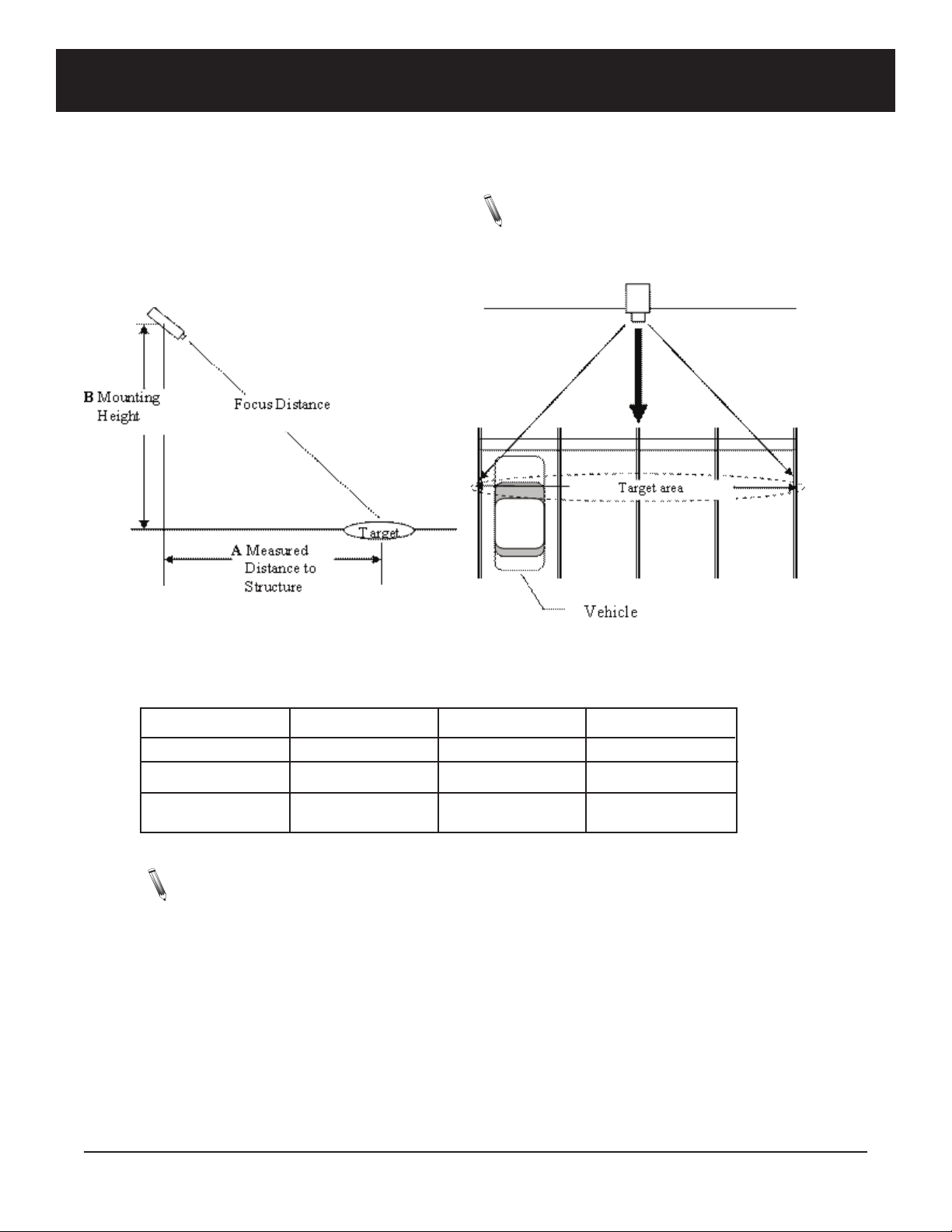
Selecting Camera Mounting Height . . . . . . . . . . . . . . . . . . . . . . . . . . . . . . . . . . . . . 4
Basic Power Connections . . . . . . . . . . . . . . . . . . . . . . . . . . . . . . . . . . . . . . . . .
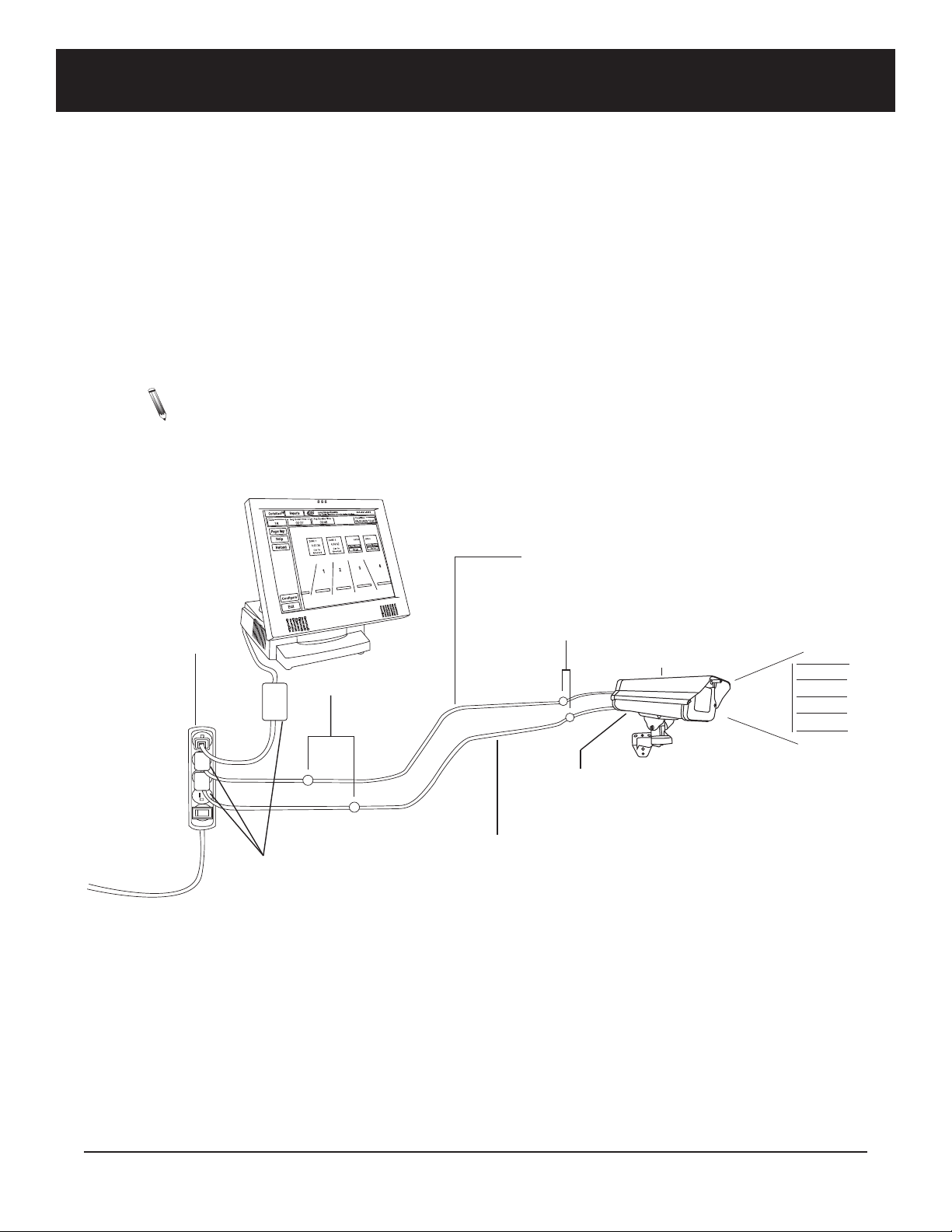
Camera Signal Connections (Preferred Connection) . . . . . . . . . . . . . . . . . . . . . 5
Using a Laptop to a just the Curbsi e Camera . . . . . . . . . . . . . . . . . . . . . . . . . . . . 6
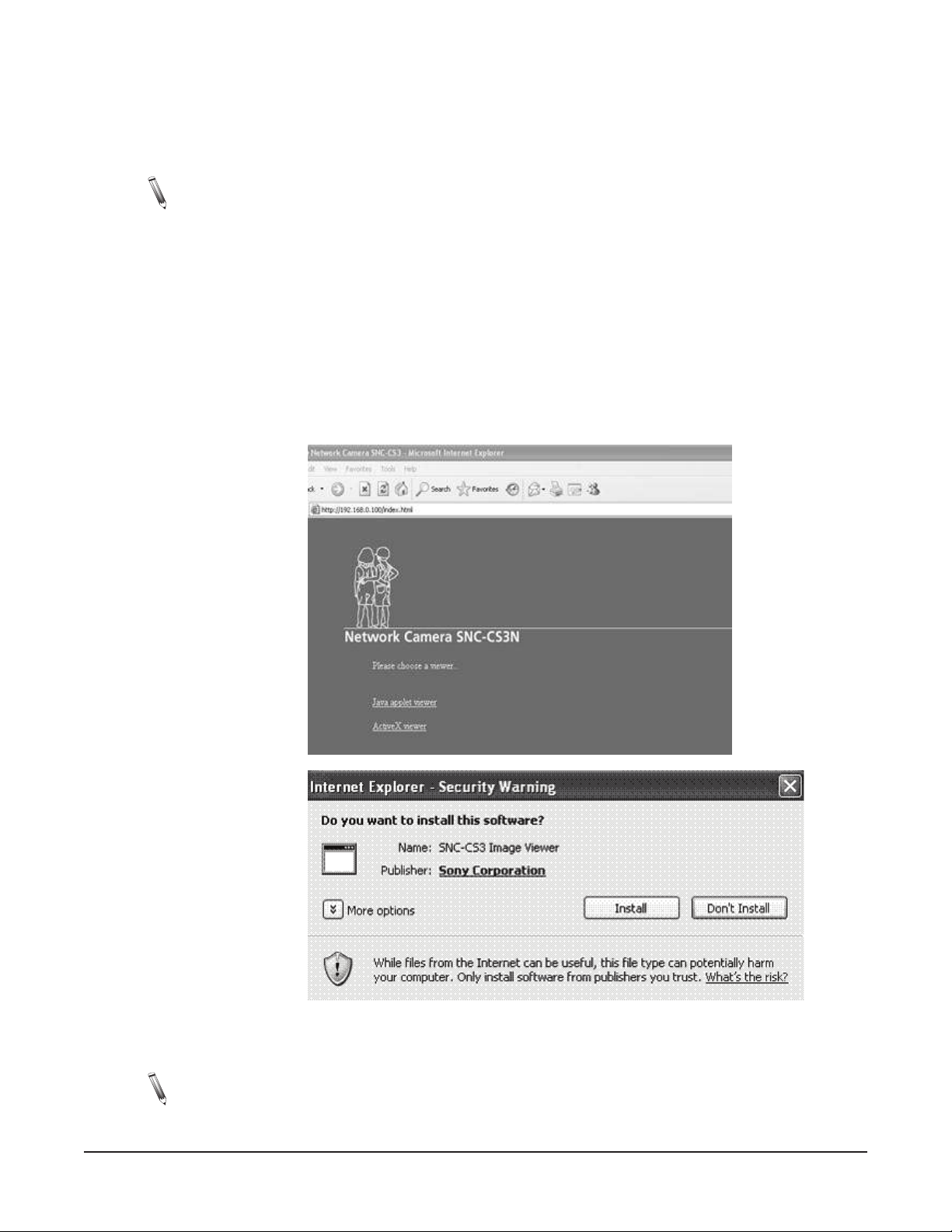
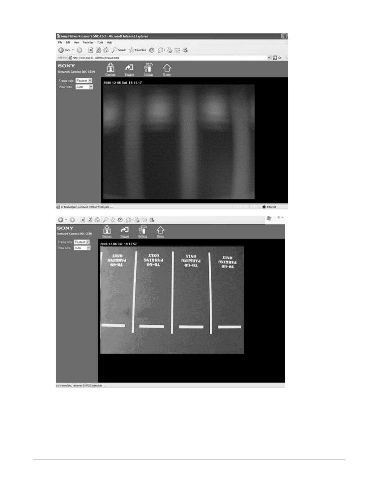
Live Vi eo Setup . . . . . . . . . . . . . . . . . . . . . . . . . . . . . . . . . . . . . . . . . . . . . . . . . . . . . 6
Laptop Manual Network Setup . . . . . . . . . . . . . . . . . . . . . . . . . . . . . . . . . . . . . . . . . . 8
Network Signal Connections (Alternate Connection . . . . . . . . . . . . . . . . . . . . . 11
Configure System . . . . . . . . . . . . . . . . . . . . . . . . . . . . . . . . . . . . . . . . . . . . . . . 12
General Proce ure . . . . . . . . . . . . . . . . . . . . . . . . . . . . . . . . . . . . . . . . . . . . . . . . . . . . 12
Setup System Screen . . . . . . . . . . . . . . . . . . . . . . . . . . . . . . . . . . . . . . . . . . . . . . . . . 13
Network . . . . . . . . . . . . . . . . . . . . . . . . . . . . . . . . . . . . . . . . . . . . . . . . . . . . . . . . . . . . . 13
Camera . . . . . . . . . . . . . . . . . . . . . . . . . . . . . . . . . . . . . . . . . . . . . . . . . . . . . . . . . . . . . 13
Software Upgra e . . . . . . . . . . . . . . . . . . . . . . . . . . . . . . . . . . . . . . . . . . . . . . . . . . . . 13
Setup Paging Screen . . . . . . . . . . . . . . . . . . . . . . . . . . . . . . . . . . . . . . . . . . . . . . . . . . 14
Pagers . . . . . . . . . . . . . . . . . . . . . . . . . . . . . . . . . . . . . . . . . . . . . . . . . . . . . . . . . . . . . . 14
Setup Sche ule Screen . . . . . . . . . . . . . . . . . . . . . . . . . . . . . . . . . . . . . . . . . . . . . . . . 15
Manager Paging . . . . . . . . . . . . . . . . . . . . . . . . . . . . . . . . . . . . . . . . . . . . . . . . . . . . . . 15
Duty Paging . . . . . . . . . . . . . . . . . . . . . . . . . . . . . . . . . . . . . . . . . . . . . . . . . . . . . . . . . 15
Zones Screen . . . . . . . . . . . . . . . . . . . . . . . . . . . . . . . . . . . . . . . . . . . . . . . . . . . . . . . . 16
Alert Zone Setup . . . . . . . . . . . . . . . . . . . . . . . . . . . . . . . . . . . . . . . . . . . . . . . . . . . . . 16
Greet Zone Setup . . . . . . . . . . . . . . . . . . . . . . . . . . . . . . . . . . . . . . . . . . . . . . . . . . . . . 17
Tuning Screen . . . . . . . . . . . . . . . . . . . . . . . . . . . . . . . . . . . . . . . . . . . . . . . . . . . . . . . 18
Location Setting Screen . . . . . . . . . . . . . . . . . . . . . . . . . . . . . . . . . . . . . . . . . . . . . . . 19
OEM TX Setup . . . . . . . . . . . . . . . . . . . . . . . . . . . . . . . . . . . . . . . . . . . . . . . . . . 20
Service Questions and Answers . . . . . . . . . . . . . . . . . . . . . . . . . . . . . . . . . . . . . 21
Warranty . . . . . . . . . . . . . . . . . . . . . . . . . . . . . . . . . . . . . . . . . . . . . . . . . . . . . . . 22
Long Range Systems 1CurbAlert User Manual

Long Range Systems 2CurbAlert User Manual
SYSTEM INSTALLATION
Tools Required
Generally many of these are items normally carrie by an installer. However this list shoul be consulte to
ensure specialty items are at the site.
Note: If possible a survey of the site prior to installation will assure the proper equipment is on
site.
• Laptop running Win ows 2000 or XP an LRS camera a justment software.
• Crossover cable (connecte to camera)
• CAT 5 cable on a reel (enough to o a 100-ft installation)
• CAT 5 crimping tool
• 18/2 speaker wire (enough to o a 100-ft installation)
• Surge Protector (in case an extra is nee e )
• Phillips Hea Screw river
• Wire Cutters/Strippers
• RJ-45 cable tester
• Volt-ohm Meter
• #8, #10 pan hea Phillips screws (assorte lengths)
• Wire Nuts an /or Electrical Tape
• Jeweler’s screw river kit.
• (2) Walkie Talkies or (2) cell phones
• La ers
• Con uit
• Drill with assorte bits (e.g., masonry bit or 12” long bit).
• OEM TX Kit

CAMERA INSTALLATION
Selecting Camera Mounting Heig t
1. Locate the 4 spaces a jacent to the buil ing that will be use for curbsi e viewing.
2. Determine the closest normal position of vehicles in the space. This is the Target area.
Note: Camera shoul align with the center of the
parking slots an have an unobstructe
view.
3. Measure the istance to the structure where the camera will be mounte (A).
4. Calculate the Require mounting height (B). Note: approximate mounting height can be calculate
using the following chart.
Mounting below 15 feet is not recommmen e
Note: This table is set for the minimum focus length for the camera. The zoom can be use to
exten the range.
Example: A is 30 feet. The camera can be mounte at any of the heights in the table (higher the bet-
ter) an zoome to a just for the target area.
TABLE GENIE
A
6 - 8 ft
8 - 10 ft
10 - 12 ft
Mounting Height
20 ft
19 ft
18 ft
A
12 - 14 ft
More then 14 ft
Mounting Height
16 ft
15 ft
Long Range Systems 3CurbAlert User Manual

BASIC POWER CONNECTIONS
1. Determine where monitor will be mounte .
2. Route AC source power to the monitor
3. Select the “To Go” parking area where the camera will be mounte .
4. Route 24 VAC source power to the camera housing fan an heater.
• Locate the wire at the camera housing marke 24VAC/15VDC.
• Splice a connecting wire to the 24VAC/15VDC power supply
• Splice the wire to the 24VAC/15VDC power supply
5. Route 24 VAC source power to the camera.
• Locate the wires at the camera housing marke 24VAC/15VDC.
• Splice connecting wires to the 24VAC/15VDC power supply
• Splice the wires to the 24VAC/15VDC connections at the power supply.
Note: The 24VAC Power Supply provi e for camera must be connecte positive-positive, neg-
ative-negative.
NOTICES:
• T e Surge protector must be mounted near t e MONITOR and all items s own are connected to it!
• T is is a touc screen monitor it must be accessible to t e users.
OFF
ON
Power Supplies
Surge Protector
Splice
Monitor
Camera
Heater/Fan
Splice
Extension Wire Suppied
by Installer
24VAC/15VDC
Parking Spaces
Long Range Systems 4CurbAlert User Manual

CAMERA SIGNAL CONNECTIONS (PREFERRED CONNECTION)
System is configure for crossover connection
1. Focus an a just camera fiel of view (See Cameral Installation page 2).
2. Route an connect crossover signal cable from the camera to the monitor.
3. Set up an test Monitor Alert parameters (see Configure System page 18).
NOTICE:
• Any junction boxes or cable routing must be sealed and weat er protected.
OFF
ON
Surge Protector
Camera
Cat 5 Coupler
Cat 5 Network Cable Supplie by Installer
Cat 5 Network Cable Supplie in Kit
Cat 5 Crossover Cable Supplied in Camera Housing
Parking Spaces
Monitor
Long Range Systems 5CurbAlert User Manual

Long Range Systems 6CurbAlert User Manual
Using a Laptop to adjust t e Curbside Camera
This is an OPTIONAL setup using a portable laptop computer. It allows an installer to a just the camera
while in the vicinity of the camera. The Laptop must be setup for using a crossover cable an the IP a ress
must be set to facilitate this function.
Note: The operating monitor an ra io communication can be use as an alternate metho of
a justing the camera
Live Video Setup
1. Locate the camera where it will be use an apply power.
2. Setup the laptop IP a ress on the computer being use for the a justment (see Laptop Manual
Network Setup on next page).
3. Connect the camera network output through the orange or re crossover cable from the camera
housing to the computer an apply power to the camera.
4. Open Internet Explorer Browser, select A ress: 192.168.0.100. The program opens with Network
Camera SNC-CS3N view.
5. Select Active X Viewer.
6. If the Active X warning appears, click on the warning to install Active X (passwor an user name
= a min).
Note: Check pop up bar if pop up blocker is active.
7. Install the Active X program.

Use Live Vi eo to a just camera.
8. When finishe with camera a justment, return Laptop to normal network mo e an connect cam-
era to system for final setup.
Long Range Systems 7CurbAlert User Manual

Long Range Systems 8CurbAlert User Manual
Laptop Manual Network Setup
C anging to Static
CAUTION: When changing the configuration, be ure to note the propertie BEFORE you make change
o that you can return the computer to it original configuration.
Note: This proce ure may vary slightly epen ing upon the version of Win ows being use .
1. From Settings Menu, select Local Area
Connection.
2. Select Properties.
3. Highlight Internet Protocol (TCP/IP) then select
Properties.
Note: Before changing, make note of the
TCP/IP properties of the local area
connection so they may be reset
when one.
4. Select “Use the Following IP a ress”
5. Set the manual properties as shown.
• IP A ress 192.168. 0 .254
• Subnet mask 255.255.255. 0
• Default Gateway 192.168. 0 .254
Optional Preferre DNS server
192.168. 0 .254
6. Select Okay until returne to normal isplay screen.

C anging to DHCP or preset Static
1. When a justments are complete, return lap-
top to normal settings.
Note: This proce ure may vary slightly e-
pen ing upon the version of Win-
ows being use .
2. From Settings Menu, select Local Area Con-
nection.
3. Select Properties.
4. Highlight Internet Protocol (TCP/IP) then se-
lect Properties.
Long Range Systems 9CurbAlert User Manual

5. Select “Use the Following IP a ress”
6. Either select:
• Obtain an IP A ress automatically or
• Reset the manual properties note in step 3
of the above proce ure.
7. Select Okay until returne to normal isplay
screen.
Long Range Systems 10 CurbAlert User Manual

Long Range Systems 11 CurbAlert User Manual
Network Si nal Connections (Alternate Connection)
Setup when connecting to a user’s network. NOTE: the system will operate without network connection.
1. Focus an a just camera fiel of view (See Cameral Installation page 2).
2. Route an connect signal cable from the router to the camera.
3. Route an connect signal cable from the router to the monitor.
4. Set up an test Monitor Alert parameters (see Configure System page 12).
5. Connect the user’s local network to the system (use primarily for obtaining up ates).
OFF
ON
Surge Protector
Camera
Cat 5 Coupler
Cat 5 Network Cable Supplie by Installer
Cat 5 Cable From Basic Kit
Cat 5 Crossover Cable Supplied in Camera Housing
Cat 5 Network Cable
From Router Kit
Router
LAN Cable to Network
Supplied by Use
LAN1
LAN2
WAN
Parking Spaces

Long Range Systems 12 CurbAlert User Manual
CONFIGURE SYSTEM
After the Camera is a juste for the target area, the monitor is set up to alert when a car has arrive .
General Procedure
At the Main Viewing Screen Select the CONFIGURE button an enter the pass co e to enable the setup
menus.
Four screens are use for setup. Each is enable by selecting the CONFIGURE button at the main viewing
screen.
• Setup consists of three functions
1. System sets basic camera, network an timing goals.
2. Paging sets up server manager an uty pagers.
3. Sche ule sets intervals for perio ic paging.
• Zones is use to efine the etection zones.
• Tune vi eo sets the etection threshol .
• Location efines the installation site.

Long Range Systems 13 CurbAlert User Manual
Setup System Screen
Network
This is the connection to the camera. The host system must be set to communicate with the camera.
• If using irect connection press the CO Cable button.
• If connecting through a network, press the DHCP button. This requires the camera to be rec-
ognize on the network an an IP a ress must be assigne .
Camera
IP address
The IP a ress for the Sony camera is 192.168.0.100 (The Use ActiveX box must NOT be checke ). This is
use for the crossover ( irect) connection. If an IP a ress must be assigne (a network irector usually as-
signs this a ress), the camera must be setup for this a ress using the camera a justment program (see
page 4).
Resolution
The resolution buttons are not use with this camera.
Software Upgrade
This function shoul only be use at the irection of LRS. If a software upgra e is require the system must
be connecte to the Internet.

Long Range Systems 14 CurbAlert User Manual
Setup Paging Screen
To setup the alphanumeric pagers use with this system.
Pagers
• System ID – istinguishes pages to particular systems to prevent interference in the event more
than one LRS paging system is in the area.
• Manager Pager – this number is the pager assigne to the manager. It will receive pages when
greet an elivery times are excee e an perio ic up ates of system status.
• Server pager – this is the number of the pager assigne to the server who is taske with greet-
ing the curbsi e customer.
• Duty Pager – these are numbers assigne to people who may o perio ic tasks (e.g., refill the
napkin ispenser, etc.).
• Paging elays
Paging Delays (in seconds)
• Car in Lane – how long a car is etecte before the server is page .
• Greet Time Page – how long a car is in lane before the manager is notifie the greet time is ex-
cee e .
• Service Time page – how long a car is in lane before the manager is notifie the service time is
excee e .

Long Range Systems 15 CurbAlert User Manual
Setup Sc edule Screen
Sche ules perio ic paging to manager an uty pagers.
Manager Paging
Enables, sets the interval, an time perio for sen ing the manager up ates of average greet times an serv-
ing times.
Duty Paging
Enables, sets the interval, an time perio for sen ing the uty person a remin er message to perform a pe-
rio ic uty.

Long Range Systems 16 CurbAlert User Manual
Zones Screen
This screen is use to assign the etection zones.
Alert Zone Setup
This is the zone where arriving traffic will alert staff.
1. Select the zone esire (Z1 – Z6).
2. Press the Assign button.
3. Touch to select the zone outline.
4. Press the Save button.
5. The zone outline will be shown.

Greet Zone Setup
This is the zone where serving staff automatically sets off the
Greet etect.
1. Select the zone esire (G1 – G6).
2. Press the Assign button.
3. Touch the position for the zone
4. Press the Save button.
5. The zone Position will be shown.
6. The Zone Size sli er a justs the zone size (for
greater sensitivity this shoul be as small as pos-
sible).
Note:
• The area where the greet zone is selecte shoul
be marke to show greeters where to walk to set
off the Greet etection.
• Several zones can be stacke to etect if greeters
walk through a selecte area (if multi cars have
arrive this will show all Alert zones as greete ).
Long Range Systems 17 CurbAlert User Manual

Tuning Screen
The tuning Screen is use to a just light an contrast levels for the best event etection. The efault etec-
tion is optimal for most installations. This screen shoul only be use at the irection of LRS.
For best results,
1. Clear the target area.
2. Set for LIVE.
3. Press the Reloa button.
4. A just the Threshol sli er until the zones are clear of any istortions.
5. Move a vehicle into the space an be sure the target area is highlighte .
6. Remove the vehicle an be sure the target area clears.
Stop an Start restart the camera; Reloa is use if the area is clear of targets. Return to the Curb Alert tab
Long Range Systems 18 CurbAlert User Manual

Location Setting Screen
This selection is use to enter site pertinent information. This information is use to i entify the unit to the
LRS atabase. This information is use to etermine usage an other report information. This is also re-
quire in the event a fiel upgra e is require .
Backup sen s the ata to LRS for i entification. A High Spee Internet connection is require .
Restore is use to contact LRS atabase to restore system settings. A High Spee Internet connection is re-
quire .
Long Range Systems 19 CurbAlert User Manual
Table of contents
Other LRS Transmitter manuals

LRS
LRS T9550 LCM User manual

LRS
LRS Butler II TX-1605-5 Owner's manual

LRS
LRS Freedom TX-7471 User manual

LRS
LRS Freedom T7460 User manual

LRS
LRS T9550 LCK User manual

LRS
LRS TX-7471-C232 User manual

LRS
LRS T9550 LCK User manual

LRS
LRS T9601 User manual

LRS
LRS Butler II Instruction Manual

LRS
LRS T7470 User manual
Popular Transmitter manuals by other brands

Lectrosonics
Lectrosonics T6 operating instructions

API
API DuoPak APD 2053 instructions

Dynex
Dynex DX-FMDC1 user guide

RKI Instruments
RKI Instruments 65-2443-100 Operator's manual

AMG
AMG AMG4647BR instruction manual

Technisonic Industries Limited
Technisonic Industries Limited TiL-92-SC Installation and operating instructions