Zamel PDH-250 User manual

PRZYCISK BEZPRZEWODOWY HERMETYCZNY
PDH-250
HERMETIC WIRELESS BUTTON
PDH-250
KABELLOSER HERMETISCHER TASTER
PDH-250
КНОПКА БЕСПРОВОДНАЯ ГЕРМЕТИЧНАЯ
PDH-250
BOTÓN INALÁMBRICO HERMÉTICO
PDH-250
BOTÃO SEM FIO HERMÉTICO
PDH-250
PULSANTE SENZA FILI ERMETICO
PDH-250
BOUTON SANS FIL TACTILE HERMÉTIQUE
PDH-250
PL Instrukcja obsługi GB User manual DE Benutzerhandbuch
RU Pуководство пользователя ES Manual de usuario
PT Manual do usuário IT Manuale d’uso FR Manuel de l’Utilisateur
| 2
| 8
| 14
| 20
| 26
| 32
| 38
| 44

• Znamionowe napięcie zasilania: 3 V DC
• Typ baterii: 2 x LR03 AAA – w komplecie
z przyciskiem
• Średni czas życia baterii: 24 miesiące*
• Transmisja: radiowa
• Kodowanie: kod zmienny
• Częstotliwość: 868 MHz
• Moc nadawania: ERP < 20 mW
• Zasięg działania: do 1400 m**
• Rodzaj przycisku: dotykowy
• Sygnalizacja optyczna działania: tak
– dioda LED zielona
• Sygnalizacja rozładowania baterii: tak
• Klasa ochronności: III
• Stopień ochrony: IP56
• Temperaturowy zakres pracy: od -20°C do
+55°C
• Wymiary: 76 x 39 x 19 mm
I. DANE TECHNICZNE
II. DOSTĘPNE W SPRZEDAŻY WARIANTY DZWONKA BULIK II PRO
* Czas życia baterii jest mocno zależny od częstotliwości użytkowania oraz warunków
atmosferycznych.
** Podany zasięg działania dotyczy przestrzeni otwartej. Udało się go uzyskać dzięki
zastosowaniu innowacyjnej metody modulacji sygnału. Tak duży zasięg działania
oznacza, że nadajnik ten sprawdzi się w trudnych warunkach takich jak: duża odległość
pomiędzy przyciskiem a dzwonkiem, duża ilość ścian lub innych przeszkód, które
w znaczący sposób mogą zmniejszać zasięg sygnału radiowego.
PRZYCISK BEZPRZEWODOWY HERMETYCZNY
PDH-250
PDH-250 Przycisk bezprzewodowy dotykowy hermetyczny
DRS-995 Dzwonek bezprzewodowy, sieciowy Bulik II PRO
DRS-995H Zestaw (dzwonek DRS-995 Bulik II PRO
+ przycisk hermetyczny PDH-250)
2

III. OPIS / WYGLĄD PRZYCISKU
Przycisk przeznaczony jest do współpracy z dzwonkiem BULIK II PRO
DRS-995. Zasilany jest bateryjnie (2 x bateria AAA LR03). Przycisk nie
wymaga instalacji dzwonkowej. W nadawaniu sygnału (komunikacji
z dzwonkami) wykorzystywana jest częstotliwość 868 MHz. Przycisk
wyróżnia się bardzo dużym zasięgiem w terenie otwartym wynoszącym
do 1400 m**. Do jednego dzwonka można zaprogramować maksymalnie
69 przycisków. Przyciskom można przypisać wybraną melodię. Jeden
przycisk można przypisać jednocześnie do wielu dzwonków. PDH-250
poza nowoczesnym wyglądem, brakiem ruchomych elementów (przycisk
dotykowy) cechuje się także hermetycznością. Jest odporny na dzia-
łanie czynników atmosferycznych i może być montowany na zewnątrz
pomieszczeń IP56.
IV. MONTAŻ PRZYCISKU
Przycisk PDH-250 wykonany jest w wersji hermetycznej. Jego obudo-
wa posiada stopień ochrony IP56. Przycisk jest przystosowany do pracy
w zmiennych warunkach atmosferycznych i może być montowany na ze-
wnątrz pomieszczeń.
Przycisk przystosowany jest do pracy na dowolnej powierzchni. Wyjątkiem
jest montaż na powierzchniach metalowych, który może skutkować ograni-
czeniem zasięgu działania (szczególnie nie zaleca się montażu przycisku
w metalowych osłonach). Duży zasięg działania sięgający do 1400 m**
umożliwia stosowanie nadajnika w trudnych warunkach takich jak: duża
odległość pomiędzy przyciskiem a dzwonkiem, duża ilość ścian lub innych
przeszkód, które w znaczący sposób mogą zmniejszać zasięg sygnału ra-
diowego.
Przycisk montuje się za pomocą taśmy dwustronnej lub klejów montażo-
wych. Możliwe jest także przykręcenie przycisku za pomocą dwóch wkrę-
tów montażowych. Podczas montażu za pomocą wkrętów należy zwrócić
szczególną uwagę na zachowanie hermetyczności (aby wilgoć nie dostała
się do wnętrza przycisku poprzez otwory montażowe).
3

dioda
LED
przycisk
dotykowy
wycięcie
pod śrubokręt
miejsce
na taśmę
montażową
miejsce
na otwory
montażowe
miejsce
na otwory
montażowe
Zestaw montażowy zawiera:
• 1 x przycisk bezprzewodowy
hermetyczny
• 2 x kołek montażowy
• 2 x wkręt montażowy
• 1 x taśma montażowa
dwustronna
wkręt
montażowy
kołek
montażowy
2
4

Przycisk może być montowany pionowo lub poziomo. Zalecany
sposób mocowania przycisku pokazuje rysunek na sąsiedniej stronie.
V. SYGNALIZACJA ROZŁADOWANEJ BATERII
Dioda LED w przycisku PDH-250 sygnalizuje konieczność wymiany baterii
poprzez kilkukrotne szybkie zaświecenie podczas nadawania (naciska-
nia przycisku). Informacja o rozładowanej baterii jest przekazywana do
dzwonka DRS-995 i sygnalizowana poprzez zaświecanie diody AMBILED
na czerwono (podczas odgrywania dźwięku).
VI. MONTAŻ PRZYCISKU / WYMIANA BATERII
1. Lekko odchylając śrubokrętem należy zdemontować frontową część
przycisku.
2. Wyciągnąć płytkę z elektroniką.
3. Nie demontując silikonowej uszczelki podstawę przycisku przykręcić
wkrętami lub przykleić za pomocą taśmy dwustronnej do podłoża
w wybranym miejscu. Stosować wkręty o średnicy nie większej niż 2,5
mm aby nie uszkodzić uszczelki.
4. Zamontować baterie zwracając szczególną uwagę na zachowanie
odpowiedniej biegunowości.
5. Zbliżyć palec do pola dotykowego i sprawdzić poprawność działania
przycisku (powinna zaświecić się zielona dioda LED w przycisku)
6. Zamocować elektronikę w podstawie przycisku.
7. Założyć frontową część przycisku – zwrócić uwagę na właściwe
umiejscowienie wycięcia pod śrubokręt. Dokładnie docisnąć front do
podstawy.
VII. INSTRUKCJA OBSŁUGI DZWONKA DRS-995
a) Programowanie przycisków
1. Za pomocą przycisku „MELODY” na dzwonku ustawić melodię, która ma
być przypisana do przycisku (melodii nie trzeba wybierać dla pierwszego
wpisywanego przycisku).
2. Nacisnąć i przytrzymać (około 2 s) przycisk „MELODY” do momentu aż
zielona dioda LED w dzwonku zacznie pulsować z częstotliwością 0,5 s.
3
5

3. Nacisnąć przycisk, który ma być dopisany do dzwonka – zielona
dioda LED w dzwonku zaświeci się i zgaśnie co oznacza poprawne
zaprogramowanie przycisku.
W celu wcześniejszego wyjścia z trybu programowania pilota (bez wpisywa-
nia przycisku) należy na krótko nacisnąć przycisk VOLUME lub MELODY
– dioda LED w dzwonku zostanie wygaszona.
Do dzwonka można wpisać maksymalnie 69 przycisków.
Przyciski programuje się pojedynczo (w celu dopisania nowego przycisku
każdorazowo należy wejść w tryb programowania).
Przycisk zaprogramowany do dzwonka jako pierwszy zawsze odgry-
wa aktualnie wybraną melodię.
b) Selektywne kasowanie przycisków
1. Nacisnąć i przytrzymać (około 2 s) przycisk „VOLUME” na dzwonku do
momentu aż zielona dioda LED w dzwonku zacznie błyskać.
2. Nacisnąć przycisk, który ma być usunięty z dzwonka – zielona dioda
LED w dzwonku zaświeci się i zgaśnie co oznacza poprawne usunięcie
przycisku.
W celu wcześniejszego wyjścia z trybu selektywnego kasowania (bez usu-
nięcia przycisku) należy na krótko nacisnąć przycisk VOLUME lub MELO-
DY – dioda LED zostanie wygaszona.
c) Kasowanie wszystkich przycisków i przywrócenie ustawień
fabrycznych
1. Odłączyć napięcie zasilające dzwonka (wyjąć dzwonek z gniazda
sieciowego 230 V AC)
2. Nacisnąć i przytrzymać przycisk VOLUME na dzwonku
3. Trzymając wciśnięty przycisk VOLUME załączyć napięcie zasilające
dzwonka (umieścić dzwonek w gnieździe sieciowym 230 V AC)
4. Zielona dioda LED zapali się na stałe
5. Puścić przycisk VOLUME
6. Dioda LED w dzwonku mignie 3 razy – oznacza to poprawne usunięcie
wszystkich pilotów.
6

podświetlenie
AMBILED
LED
Gniazdo
karty microSD
(gniazdo
z wyrzutnikiem)
VIII. WYGLĄD DZWONKA
Volume
Głośność
Melody
Melodia
7

• Rated voltage: 3 V DC
• Battery type: 2 x LR03 AAA – supplied with
the button
• Average battery life: 24 months*
• Transmission: radio
• Coding: variable code
• Frequency: 868 MHz
• Transmission power: ERP <20 mW
• Range: up to 1400 m**
• Button type: touch
• Optical signalling of operation: yes – green
LED
• Warning when battery is low: yes
• Protection class: III
• Protection rating: IP56
• Operating temperature: -20°C to +55°C
• Dimensions: 76 x 39 x 19 mm
I. TECHNICAL DATA
II. TYPES OF BULIK II PRO DOOR CHIME AVAILABLE FOR SALE
* Battery life depends on usage frequency and weather conditions to a great extent.
** The range applies to an open area. It has been achieved using an innovative signal
modulation method. Such a large range means that this transmitter will work out in difcult
conditions, such as a large distance between the button and the door chime, a large
number of walls or other obstacles that can signicantly reduce the range of radio signal.
HERMETIC WIRELESS BUTTON PDH-250
PDH-250 Hermetic wireless touch button
DRS-995 Wireless plug-in door chime Bulik II Pro
DRS-995H Kit (DRS-995 Bulik II PRO door chime
+ hermetic button PDH-250)
8

III. DESCRIPTION / APPEARANCE OF THE BUTTON
The button is compatible with BULIK II PRO DRS-995. It is battery powe-
red (2 x AAA LR03). It does not require any bell installation. The 868 MHz
frequency is used to transmit signal (communicate with door chimes). The
button has a very wide range in the open area of up to 1,400 m**. A ma-
ximum of 69 buttons can be programmed for one door chime. Selected
melody can be assigned to the buttons. One button can be assigned to
many door chimes at the same time. Apart from the modern design and
lack of moving elements (touch button), PDH-250 is also hermetic. It is
resistant to weather conditions and can be mounted outside of IP56 rooms.
IV. INSTALLATION
PDH-250 is hermetic. Its housing has been assigned with IP56 protection
class. The button can operate under varying weather conditions and can be
mounted outside.
The button is adapted to work on any surface, with the only exception
being metal surfaces which can reduce its operating range (in particular,
avoid installing the button in metal covers). A large operating range of up
to 1400 m** means that this transmitter will work out in difcult conditions,
such as a large distance between the button and the door chime, a large
number of walls or other obstacles that can signicantly reduce the range
of radio signal.
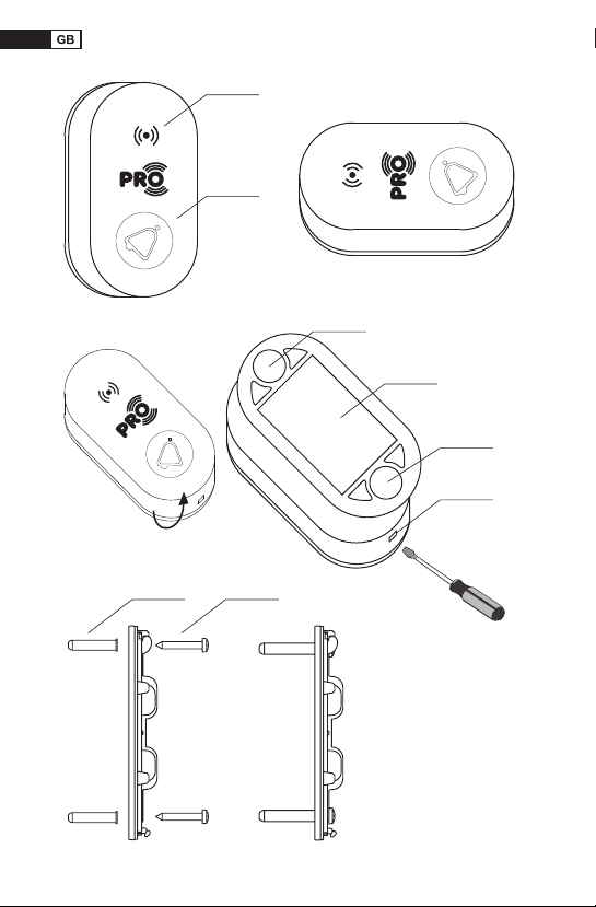
It is installed with double-sided tape or mounting adhesives. It can also be
screwed using two screws. When using the screws, particular attention
should be paid to maintain airtightness (so that moisture does not get inside
the button through the mounting holes).
The button can be mounted vertically or horizontally. The recommended
way of mounting the button is shows on the next page.
V. WARNING THAT THE BATTERY IS LOW
LED in the PDH-250 button shows that it is necessary to replace the bat-
tery when it lights several times during transmission (pressing the button).
9

LED
diode
Touch
button
Cutout for
a screwdriver
Space for
mounting
tape
Location
of mounting
holes
Location
of mounting
holes
The assembly kit
consists of:
• 1 x wireless hermetic button
• 2 x dowel
• 2 x screw
• 1 x double-sided
mounting tape
ScrewDowel
10

Information about low battery is transmitted to the DRS-995 door
chime and is signalled by lighting the AMBILED diode in red (while the
melody is playing).
VI. INSTALLATION OF THE BUTTON / BATTERY REPLACEMENT
1. Remove the front part of the button, slightly tilting it with a screwdriver.
2. Remove the electronics board.
3. Without disassembling the silicone seal, screw the base of the button
with screws or glue it with double-sided tape to the ground in the selected
place. Use screws that are not larger than 2.5 mm in diameter to avoid
damaging the seal.
4. Install the batteries paying particular attention to the correct polarity.
5. Move your nger to the touch eld and check if the button works correctly
(green LED in the button should light up).
6. Place the electronics on the button base.
7. Replace the front part of the button – pay attention to the correct position
of the screwdriver cutout. Carefully press the front to the base.
VII. DRS-995 DOOR CHIME USER MANUAL
a) Button programming
1. Use the “MELODY” button on the door chime to set the melody to be
assigned to the button (you do not have to select the melody for the rst
button).
2. Press and hold (for about 2 s) “MELODY” button until green LED in the
door chime starts ashing with a frequency of 0.5 s.
3. Press the button to be added to the door chime – green LED in the
door chime will turn on and off, which means that the button has been
correctly programmed.
In order to exit the programming mode earlier (without entering the button),
press the VOLUME or MELODY button briey – LED in the door chime will
be off.
A maximum of 69 buttons can be programmed for one door chime.
11

The buttons are programmed individually (in order to add a new button, you
must enter the programming mode again).
The rst button programmed to the door chime always plays the cur-
rently selected melody.
b) Selective removal of buttons
1. Press and hold (for about 2 s) “VOLUME” button on the door chime until
green LED in the door chime starts ashing.
2. Press the button to be removed from the door chime – green LED in the
door chime will turn on and off, which means that the button has been
correctly removed.
In order to exit the selective removal mode earlier (without removing the
button), press the VOLUME or MELODY button briey – LED will be off.
c) Removal of all buttons and restoring default settings
1. Disconnect power supply of the door chime (remove the door chime from
the 230 V AC socket).
2. Press and hold the VOLUME button on the door chime.
3. Keep the VOLUME button pressed and switch on the power supply of the
door chime (put the door chime in the 230 V AC socket).
4. The green LED will light up permanently.
5. Stop holding the VOLUME button.
6. The LED in the door chime will ash 3 times – this means that all pilots
have been correctly removed.
12

Backlight
AMBILED
LED
microSD
card slot
(with ejector)
VIII. APPEARANCE
Volume
control
Melody
13

• Nennspannung: 3 V DC
• Batterietyp: 2 x LR03 AAA - im Set mit dem
Taster
• Mittlere Lebensdauer der Batterie: 24 Monate*
• Übertragung: Funk
• Codierung: veränderlicher Code
• Frequenz: 868 MHz
• Sendeleistung: ERP < 20 mW
• Reichweite: bis zu 1400 m**
• Art des Tasters: Berührungstaster
• Optischer Betriebssignal: ja - grüne LED-
-Diode
• Signal für Batterieentladung: ja
• Schutzklasse: III
• Schutzart: IP56
• Betriebstemperaturbereich: von -20°C bis
+55°C
• Abmessungen: 76 x 39 x 19 mm
I. TECHNISCHE DATEN
II. ERHÄLTLICHE VARIANTEN DER KLINGEL BULIK II PRO
* Die Lebensdauer der Batterie ist stark von der Häugkeit der Benutzung und von den
Witterungsbedingungen abhängig.
** Die angegebene Reichweite bezieht sich auf Freifeld. Es ist gelungen, sie dank der
Anwendung der modernen Methode der Signal-Modulation zu erreichen. Eine so große
Reichweite bedeutet, dass dieser Sender sich in solch schwierigen Bedingungen wie:
großer Abstand zwischen dem Taster und der Klingel, große Anzahl an Wänden oder
anderen Hindernissen, die die Reichweite des Funksignals beachtlich reduzieren
können, bewähren wird.
KABELLOSER HERMETISCHER TASTER
PDH-250
PDH-250 Kabelloser hermetischer Berührungstaster
DRS-995 Kabellose Netz-Klingel Bulik II PRO
DRS-995H Set (Klingel DRS-995 Bulik II PRO
+ hermetischer Taster PDH-250)
14

III. BESCHREIBUNG / AUSSEHEN DES TASTERS
Der Taster ist für die Zusammenarbeit mit der kabellosen Klingel BULIK II
PRO DRS-995 bestimmt. Er ist batteriebetrieben (2 x Batterien AAA LR03).
Der Taster braucht keine Klingel-Installation. Bei der Signal-Sendung (in
Verbindung mit den Klingeln) wird die Frequenz 868 Mhz verwendet. Der
Taster zeichnet sich durch eine sehr große Reichweite im Freifeld aus, die
bis zu 1400 m beträgt**. Für eine Klingel lassen sich maximal 69 Taster
programmieren. Den Tastern kann man ein ausgewähltes Lied zuschreiben.
Einen Taster kann man gleichzeitig mehreren Klingeln zuordnen. PDH-250
zeichnet sich neben seines modernen Aussehens, und des Fehlens bewe-
glicher Teile (Berührungstaster) durch Hermetizität aus. Er ist witterungs-
beständig und kann im Außenbereich montiert werden, IP56.
IV. MONTAGE DES DRUCKTASTERS
Der Taster ist in hermetischer Version ausgeführt. Sein Gehäuse hat die
Schutzart IP56. Der Taster ist an den Betrieb bei veränderlichen Witterungs-
bedingungen angepasst und kann im Außenbereich montiert werden.
Der Taster ist an den Betrieb auf beliebiger Oberäche angepasst. Eine Au-
snahme bildet die Montage an Metalloberächen, die eine Einschränkung
der Reichweite seiner Wirkung zur Folge haben kann (insbesondere wird
von der Montage des Tasters in Metallabdeckungen abgeraten). Die große
Reichweite des Gerätes, bis zu 1400m** ermöglicht die Anwendung des
Senders in solch schwierigen Bedingungen wie: großer Abstand zwischen
dem Taster und der Klingel, große Anzahl an Wänden oder anderen Hinder-
nissen, die die Reichweite des Funksignals beachtlich reduzierenkönnen.
Der Taster wird mithilfe des beidseitigen Klebebandes oder mithilfe der
Montageleime montiert. Möglich ist auch das Anschrauben des Tasters
mithilfe von zwei Montageschrauben. Während der Montage mithilfe der
Schrauben sollte man besonders darauf achten, dass die Hermetizität
erhalten bleibt (damit die Feuchtigkeit nicht durch die Montage-Öffnungen in
das Innere des Tasters gelangt).
Der Taster kann senkrecht und waagerecht montiert werden. Die empfohle-
ne Befestigungsart zeigt das Bild auf der Seite nebenan.
15

LED-Diode
Berührungs-
taster
Ausschnittt für den
Schraubenzieher
Stelle für das
Montage-
Klebeband
Montage-
Öffnungen
Montage-
Öffnungen
Der Montage-Set beinhaltet:
• 1 x kabellosen, hermetischen
Taster
• 2 x Montagestift
• 2 x Montageschraube
• 1 x beidseitiger Montage-
Klebeband
MontageschraubeMontagestift
16

V. SIGNAL FÜR BATTERIEENTADUNG
Bei dem Taster PDH-250 signalisiert die LED-Diode durch ein mehrfaches
schnelles Aueuchten während des Sendens (Drückens des Tasters), dass
ein Batterieaustausch erforderlich ist. Die Information über die Batterieen-
tladung wird an die Klingel DRS-995 weitergeleitet und durch das Aue-
uchten der Diode AMBILED in Farbe Rot (während des Abspielens des
Klingeltons) signalisiert.
VI. MONTAGE DES DRUCKTASTERS / BATTERIEAUSTAUSCH
1. Heben Sie mit dem Schraubenzieher leicht den Frontteil des Tasters an
und demontieren Sie ihn.
2. Nehmen Sie die Platte mit der Elektronik heraus.
3. Schrauben Sie die Basis des Drucktasters mit Schrauben an oder kleben
Sie sie mithilfe eines beidseitigen Klebebandes an den Untergrund
an einer ausgewählten Stelle an, ohne dabei die Silikondichtung zu
demontieren. Verwenden Sie dabei Schrauben mit einem Durchmesser
von höchstens 2,5 mm, um nicht die Dichtung zu beschädigen.
4. Montieren Sie die Batterie, indem Sie dabei besonders auf die Einhaltung
der entsprechenden Polarität achten.
5. Nähern Sie den Finger dem Druckfeld und überprüfen Sie, ob der Taster
funktioniert (es sollte die grüne LED-Diode am Taster aueuchten).
6. Montieren Sie die Elektronik in der Basis des Tasters.
7. Setzen Sie den Frontteil des Tasters auf - indem Sie besoders auf die
richtige Anordnung der Schraubenzieher-Öffnungen achten. Drücken Sie
die Front fest an die Basis an.
VII. BEDIENUNGSANLEITUNG DER KLINGEL DRS-995
a) Programmieren der Taster
1. Stellen Sie mithilfe der Taste „MELODY“ die Melodie der Klingel ein, die
dem Taster zugeordnet werden soll (die Melodie muss man nicht für den
ersten eingetragenen Taster auswählen).
2. Die Taste „MELODY“ drücken und (etwa 2 s) gedrückt halten, bis die
grüne LED-Diode der Klingel aueuchtet und anfängt mit einer Frequenz
von 0,5 s zu blinken.
17

3. Den Taster drücken, der der Klingel zugeordnet werden soll - die grüne
LED-Diode der Klingel wird aueuchten und erlöschen, was bedeutet,
dass der Taster korrekt programmiert ist.
Um den Programmiermodus der Fernbedienung früher zu verlassen (ohne
den Taster einzutragen), sollte man kurz die Taste VOLUME oder MELODY
drücken - die LED-Diode der Klingel wird ausgehen.
Für eine Klingel lassen sich maximal 69 Taster eintragen.
Die Taster werden einzeln programmiert (um einen neuen Taster hinzuzufü-
gen sollte man jedesmalig auf den Programmiermodus umschalten).
Der Taster, der als erster der Klingel zugeschrieben wird, spielt immer
die aktuell gewählte Melodie ab.
b) Selektives Löschen der Taster
1. Die Taste „VOLUME“ drücken und (etwa 2 s) gedrückt halten, bis die
grüne LED-Diode der Klingel anfängt zu blinken.
2. Den Taster drücken, der von der Kingel entfernt werden soll - die grüne
LED-Diode der Klingel wird aueuchten und erlöschen, was bedeutet,
dass der Taster korrekt entfernt wurde.
Um den Modus des selektiven Löschens früher zu verlassen (ohne den
Taster zu entfernen), sollte man kurz die Taste VOLUME oder MELODY
drücken - die LED-Diode wird ausgehen.
c) Löschung aller Taster und Wiederherstellung der Hersteller-
Einstellungen
1. Die Klingel vom Strom trennen (die Klingel aus der 230 V AC-Steckdose
ziehen).
2. Die VOLUME-Taste drücken und gedrückt halten.
3. Schalten Sie die Klingel, indem Sie die VOLUME-Taste gedrückt halten,
an den Strom an (platzieren Sie die Klingel in der 230 V AC-Steckdose).
4. Die grüne LED-Diode wird dauerhaft leuchten.
5. Die VOLUME-Taste loslassen.
6. Die LED-Diode der Klingel wird drei Mal aueuchten - das bedeutet eine
korrekte Entfernung aller Fernbedienungen.
18

Beleuchtung
AMBILED
LED
Steckplatz der
microSD-Karte
(Steckplatz mit
Herausschieb-
emöglichkeit)
VIII. AUSSEHEN DER KLINGEL
Volume
Lautstärke
Melody
Melodie
19

• Номинальное напряжение питания: 3 В
постоянного тока
• Тип батарей: 2 x LR03 AAA – в комплекте
с кнопкой
• Средний срок службы батарей: 24 месяца*
• Передача: радио
• Кодирование: переменный код
• Частота: 868 МГц
• Мощность передачи: ERP < 20 мВт
• Дальность действия: до 1400 m**
• Вид кнопки: сенсорная
• Оптическая индикация работы: да
– зеленый светодиод
• Индикация разрядки батарей: да
• Класс защиты: III
• Степень защиты: IP56
• Диапазон рабочих температур: от
- 20°C до +55°C
• Размеры: 76 x 39 x 19 мм
I. ТЕХНИЧЕСКИЕ
ДАННЫЕ
II. ВАРИАНТЫ ЗВОНКА BULIK II PRO, ДОСТУПНЫЕ В ПРОДАЖЕ
* Срок службы батарей в значительной мере зависит от частоты эксплуатации и
атмосферных условий.
** Указанная дальность действия относится к открытому пространству. Дальность
действия достигнута благодаря инновационному методу модуляции сигнала.
Такая большая дальность действия означает, что данный передатчик адаптирован
для работы в сложных условиях, таких как: большое расстояние между кнопкой
и звонком, большое количество стен или других препятствий, которые могут
значительно уменьшить дальность действия радиосигнала.
КНОПКА БЕСПРОВОДНАЯ ГЕРМЕТИЧНАЯ
PDH-250
PDH-250 Беспроводная кнопка сенсорная герметичная
DRS-995 Беспроводной звонок, сетевой Bulik II PRO
DRS-995H Комплект (звонок DRS-995 Bulik II PRO
+ герметичная кнопка PDH-250)
20
This manual suits for next models
2
Table of contents
Languages:
Other Zamel Transmitter manuals

Zamel
Zamel RNL-01 User manual

Zamel
Zamel RNK-02 User manual

Zamel
Zamel ROP-01 User manual

Zamel
Zamel RTN-01 User manual

Zamel
Zamel RNP-22 User manual

Zamel
Zamel exta life RNK-22 User manual

Zamel
Zamel RNK-02 User manual

Zamel
Zamel exta life RNK-22 User manual

Zamel
Zamel EXTA LIFE RNP-21 User manual

Zamel
Zamel EXTA LIFE RNM-24 User manual