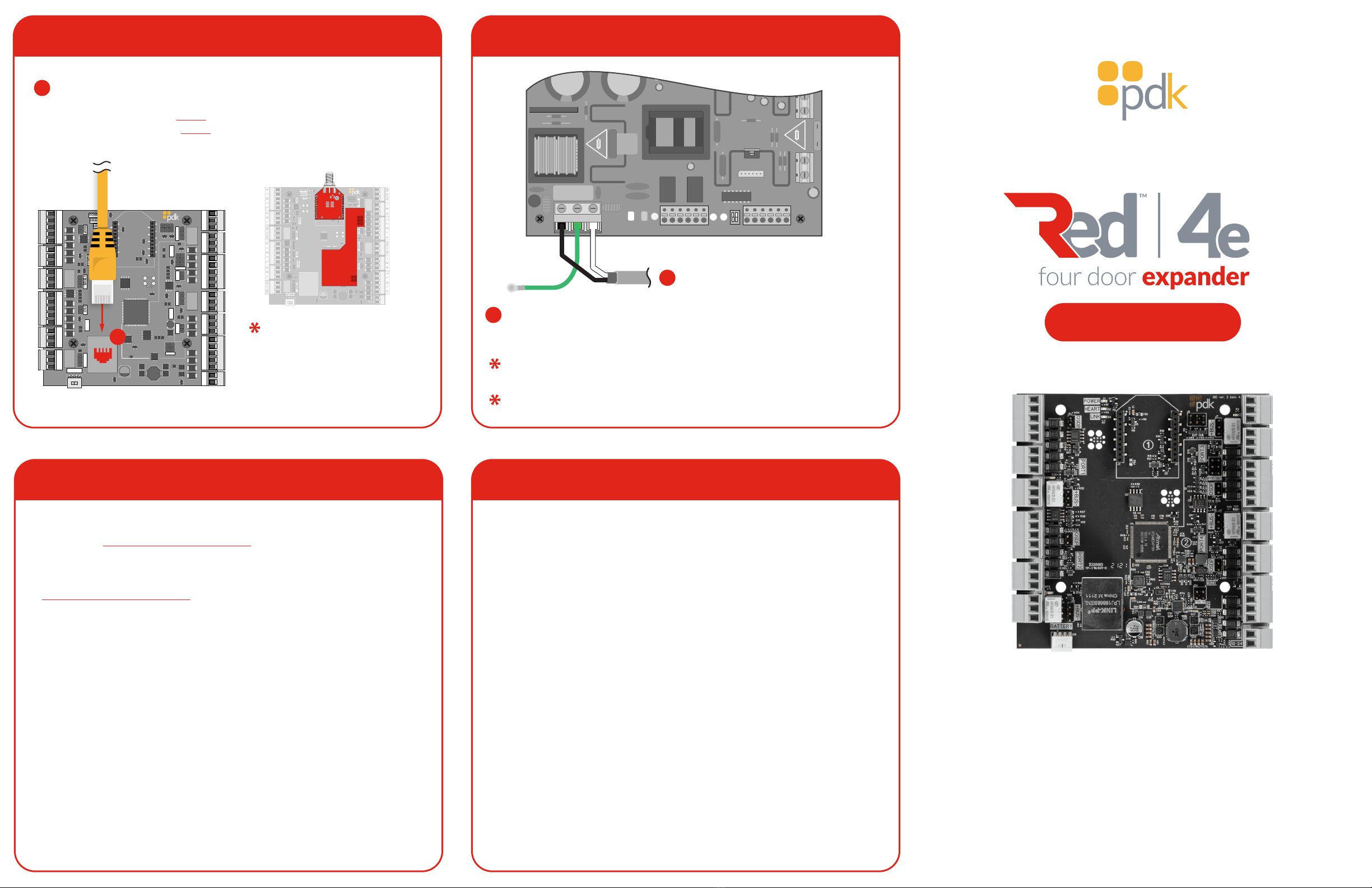
manuals.online logo
Brands
  1. Home
  2. •
  3. Brands
  4. •
  5. PDK
  6. •
  7. Extender
  8. •
  9. PDK Red 4e User manual

PDK Red 4e User manual

3. Reader Connection2. Mounting the Expander Board
6. Locking Relay
5. Input B / REX Connection4. Input A / DPS Connection
1. Mounting the Power Supplies
Mount - Line up the power supplies with the top mounting brackets in the enclosure.
Using the supplied screws, fasten the power supplies to the enclosure.
Backup
Battery
Backup
Battery
Power Supply
Board
Power Supply
Board
AC1
AC
DC
NC
C
NO
NC
C
NO
eFlow102B
5A 250V
15A 32V
eFlow102NB
L G N
ALTRONIX CORP.
BROOKLYN,
N.Y. 11220
+ AUX –
TRIGGEREOL
SUPERVISED RESET
NO
GND
+
-
DC
+
-
BAT
AC1
AC
DC
NC
C
NO
NC
C
NO
eFlow102B
5A 250V
15A 32V
eFlow102NB
L G N
ALTRONIX CORP.
BROOKLYN,
N.Y. 11220
+ AUX –
TRIGGEREOL
SUPERVISED RESET
NO
GND
+
-
DC
+
-
BAT
Mount - Select your desired mounting location within the enclosure. Line up the
expander board with the desired mounting brackets. Using the supplied screws,
fasten the expander board to the enclosure.
AC1
AC
DC
NC
C
NO
NC
C
NO
eFlow102B
5A 250V
15A 32V
eFlow102NB
L G N
ALTRONIX CORP.
BROOKLYN,
N.Y. 11220
+ AUX –
TRIGGEREOL
SUPERVISED RESET
NO
GND
+
-
DC
+
-
BAT
AC1
AC
DC
NC
C
NO
NC
C
NO
eFlow102B
5A 250V
15A 32V
eFlow102NB
L G N
ALTRONIX CORP.
BROOKLYN,
N.Y. 11220
+ AUX –
TRIGGEREOL
SUPERVISED RESET
NO
GND
+
-
DC
+
-
BAT
Expansion
Board
Expansion
Board
Expansion
Board
Expansion
Board
Expansion
Board
Expansion
Board
AReader(s) - The reader is mounted at the door with a 22/5 or 22/6 wire
running to the door controller. Wire the reader to the controller as shown
above. Be sure to check polarity and voltage prior to powering the controller.
BOSDP - Place jumper(s) to enable OSDP (see reference guide for more
information about OSDP.)
OSDP
Wiring
+
-
0 1 L
B
AReader(s)
POWER
HEART
LINK
BUS
+-BUS
+-
BUS
+-BUS
+-
POE IN
POE OUT
12-24
GND
+
BATTERY
+
-
0 1 L A
-
B NC NOC
+
-
0 1 L A
-
B NC NOC
OSDP OSDP
OSDP OSDP PORT2
PORT3
PORT4
PORT1
+
-
0 1 L A
-
B NC NOC
+
-
0 1 L A
-
B NC NOC
A
A
A
OSDP
+
C
CPiezo - Can be connected to available relay and configured with software
ADPS (Door Position Sensor) - The DPS is mounted on the door frame with a
22/2 wire running from the DPS to the controller. Wire the DPS to the
controller as shown above. For reporting double doors, wire the two-door
position sensors in series and connect them to the controller.
AUX Input - A software rule can be programmed to trigger events or
outputs based on input triggers.
B
POWER
HEART
LINK
BUS
+-BUS
+-
BUS
+-BUS
+-
POE IN
POE OUT
12-24
GND
+
BATTERY
+
-
0 1 L A
-
B NC NOC
+
-
0 1 L A
-
B NC NOC
OSDP OSDP
OSDP OSDP PORT2
PORT3
PORT4
PORT1
+
-
0 1 L A
-
B NC NOC
+
-
0 1 L A
-
B NC NOC
A
DPS Contact
B
A
-
B
Double
DPS Contact
Maglock - When installing a maglock, it is typical to install a REX (request to
exit) at the door for free egress. Run an 18/2 wire from the maglock to the
controller and REX as shown.
A
REX (Request to Exit) - The REX is mounted at your desired location with an
18/5 wire. Wire the REX to the controller and maglock, as shown above. If
reporting is not needed in the software, simply eliminate the green input
wire.
B
Jumper Block(s) -Use to designate (+) or (-) board voltage out of NO and NC.
If the jumper is off, the relay is a standard dry contact requiring an input into C
on the relay.
C
If using a powered REX,
run to any 12VDC output
on the controller.
POWER
HEART
LINK
BUS
+-BUS
+-
BUS
+-BUS
+-
POE IN
POE OUT
12-24
GND
+
BATTERY
+
-
0 1 L A
-
B NC NOC
+
-
0 1 L A
-
B NC NOC
OSDP OSDP
OSDP OSDP PORT2
PORT3
PORT4
PORT1
+
-
0 1 L A
-
B NC NOC
+
-
0 1 L A
-
B NC NOC
Maglock
BREX
A
CBUS
+-
D
DAUX Input - A software rule can be programmed to trigger events or outputs
based on input triggers.
POWER
HEART
LINK
BUS
+-BUS
+-
BATTERY
+
-
0 1 L A
-
B NC NOC
+
-
0 1 L A
-
B NC NOC
OSDP OSDP PORT2
PORT1
D
BUS
+-
C
A
BOR
Diode - The provided diode must be installed when using a strike. Install at
the strike with the gray stripe on positive and black on negative.
A
NC - Used for maglocks (or strikes in fail-safe configuration). Connect the
negative (-) of the maglock or strike to NC on the controller.
B
NO - Used for strikes in fail-secure configuration. Connect the negative (-) of
the strike to NO on the controller.
C
Jumper Block - Use to designate (+) or (-) board voltage out of NO and NC. If
the jumper is off, the relay is a standard dry contact requiring an input into C
on the relay.
D
Reference Guide
8. Power Connection
OSDP Reference Guide
7. Communication Connections
POWER
HEART
LINK
BUS
+-BUS
+-
BUS
+-BUS
+-
POE IN
POE OUT
12-24
GND
+
BATTERY
+
-
0 1 L A
-
B NC NOC
+
-
0 1 L A
-
B NC NOC
OSDP OSDP
OSDP OSDP PORT2
PORT3
PORT4
PORT1
+
-
0 1 L A
-
B NC NOC
+
-
0 1 L A
-
B NC NOC
Ethernet - All Red controllers come with a built-in RJ45 connection for
network connectivity. Once connected, the Red controller is
Self-Discoverable from pdk.io using IPV6. Alternatively, you may use IPV4
or assign a static IP using pdk.io if desired.
A
Wireless (PN: RMW) and
PoE (PN: RMPOE) module
kits can be purchased for
optional communication
methods.
A
POWER
HEART
LINK
BUS
+-BUS
+-
BUS
+-BUS
+-
POE IN
POE OUT
12-24
BATTERY
+
-
0 1 L A
-
B NC NOC
+
-
0 1 L A
-
B NC NOC
+
-
0 1 L A
-
B NC NOC
+
-
0 1 L A
-
B NC NOC
OSDP OSDP
OSDP OSDP PORT2
PORT3
PORT4
PORT1
Powering Board - Connect unswitched AC power (120VAC 60Hz) to
terminals marked [L, G, N]. L to hot, N to neutral, G to ground. Use 14 AWG or
larger for all power connections. Secure green wire lead to earth ground.
A
Disclaimer -Installers must adhere to all regulations and hold the proper
state licenses prior to supplying voltage to the power supply.
Battery Backup is strongly recommended on all ProdataKey hardware. The
recommended backup battery for the Red Max is two 12V 12ah batteries.
AC1
AC
DC
NC
C
NO
NC
C
NO
eFlow102B
5A 250V
15A 32V
eFlow102NB
L G N
ALTRONIX CORP.
BROOKLYN,
N.Y. 11220
+ AUX –
TRIGGER EOL
SUPERVISED RESET
NO
GND
+
-
DC
+
-
BAT
AC Power
120VAC 60Hz
A
What is OSDP - Open Supervised Device Protocol (OSDP) is an access
control communications standard developed by the Security Industry
Association to improve interoperability among access control and security
products. OSDP brings heightened security and improved functionality. It is
more secure than Wiegand and supports AES-128 encryption.
OSDP Wire Specification - Four-conductor, twisted-pair cable with overall
shield is recommended to remain fully TIA-485 compliant at the maximum
supported baud rates and cable distances.
Note - It’s possible to reuse existing Wiegand wiring for OSDP. However,
using a simple stranded cable typical of Wiegand readers generally does not
meet the RS-485 twisted pair recommendations.
OSDP Multi-Drop - Multi-drop gives you the capability to accommodate
many readers by running one length of four-conductor cable, eliminating the
need to run wire for each wire.
Note - Four (4) is the maximum number of readers each port can support.
Note - Wiegand readers will not work when OSDP jumpers are installed.
Fire Input - To integrate the fire system into a controller, refer to wiring
diagrams at www.prodatakey.zendesk.com
Programming - After the controller is connected, access the configuration
software as instructed in the programming manual available at
www.prodatakey.zendesk.com
Reader Compatibility - Pdk does not require proprietary readers.
Controllers accept a Wiegand input, including biometric readers and
keypads. OSDP readers are supported by using the included jumper (see
OSDP reference guide). Contact pdk support if assistance is needed.
UL 294 Compliance - All equipment must meet appropriate UL certifications.
For UL-listed installations, all cable runs must be less than 30 meters (98.5’)
Part Number - R4E
Pdk Technical Support
Phone: 801.317.8802 option #2
Email: support@prodatakey.com
Knowledge Base: prodatakey.zendesk.com www.prodatakey.com
801.317.8802
REV 06132022
View the user manual here:
prodatakey.zendesk.com
PN:R4E
Copyright © 2022 ProdataKey Inc. All rights reserved. Pdk, Pdk io, and
the Red logos are trademarks of ProdataKey Inc.
Quick Start Guide

This manual suits for next models

1

Popular Extender manuals by other brands

Digitus DS-55516 manual

Digitus

Digitus DS-55516 manual

LEGRAND C2G RapidRun 60218 manual

LEGRAND

LEGRAND C2G RapidRun 60218 manual

Gefen ex-tend-it Firewire Extender user manual

Gefen

Gefen ex-tend-it Firewire Extender user manual

CYP PU-1106-KIT Operation manual

CYP

CYP PU-1106-KIT Operation manual

Panasonic KX-TGA405 installation guide

Panasonic

Panasonic KX-TGA405 installation guide

RTI VXT-Ux reference guide

RTI

RTI VXT-Ux reference guide

D-Link DAP-1610 user manual

D-Link

D-Link DAP-1610 user manual

opticis M5-1002 user manual

opticis

opticis M5-1002 user manual

Lindy 38328 V2 Full user manual

Lindy

Lindy 38328 V2 Full user manual

Speaka Professional 1911200 operating instructions

Speaka Professional

Speaka Professional 1911200 operating instructions

SmoothTalker BMX650 user manual

SmoothTalker

SmoothTalker BMX650 user manual

Suitmate 115V/60Hz Installation & maintenance

Suitmate

Suitmate 115V/60Hz Installation & maintenance

IOGear GPLWE150 quick start guide

IOGear

IOGear GPLWE150 quick start guide

HOME8 WRP1220 quick start guide

HOME8

HOME8 WRP1220 quick start guide

Lindy 38163 user manual

Lindy

Lindy 38163 user manual

Daxten LONGVIEW 1000 manual

Daxten

Daxten LONGVIEW 1000 manual

Gefen EXT-DVI-CAT5-ELR user manual

Gefen

Gefen EXT-DVI-CAT5-ELR user manual

Wilson Electronics Weboost AM100-PRO installation guide

Wilson Electronics

Wilson Electronics Weboost AM100-PRO installation guide

manuals.online logo
manuals.online logoBrands
  • About & Mission
  • Contact us
  • Privacy Policy
  • Terms and Conditions

Copyright 2025 Manuals.Online. All Rights Reserved.