PCAN-Router DR – User Manual
5
1 Introduction
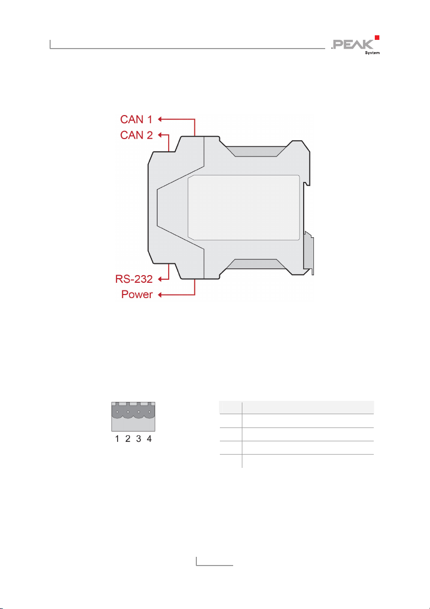
The PCAN-Router DR has two High-speed CAN channels. Their bit
rate is adjusted with a rotary switch on the device front. The module
forwards the message traffic bi-directionally 1:1 between both
connected CAN buses.
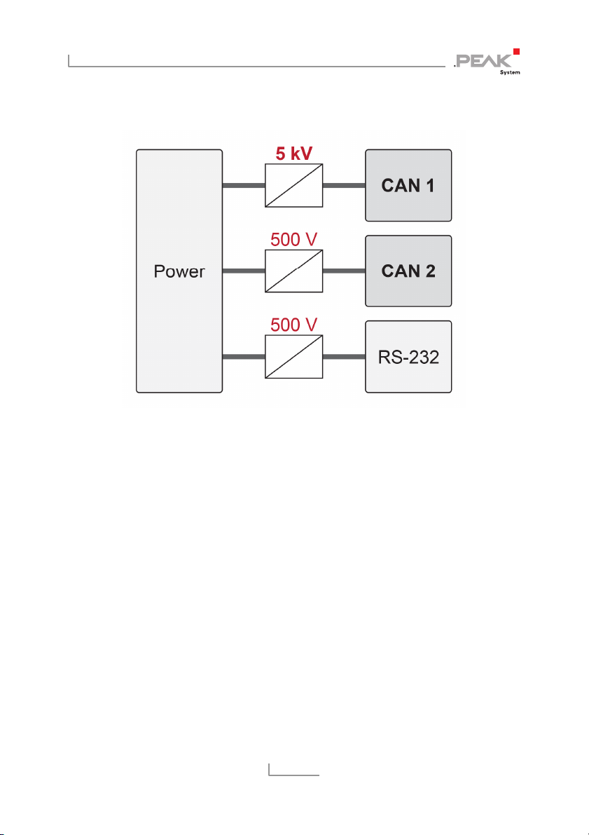
The ports of the device are isolated against each other and against
the power supply with at least 500 V. Furthermore, CAN 1 has a
separation voltage of up to 5 kV conforming with IEC 60601-1. With
its DIN rail casing and the support of the extended temperature
range, the module is suitable for use in an industrial environment.
Just like the PCAN-Router in the aluminum casing, the PCAN-Router
DR can be freely programmed. A corresponding development
package is included in the scope of supply.
1.1 Properties at a Glance
NXP LPC21 series microcontroller (16/32-bit ARM CPU)
32 kbyte EEPROM
Two High-speed CAN channels (ISO 11898-2)
Complies with CAN specifications 2.0 A/B
NXP PCA82C251 CAN transceiver
Bit rates from 5 kbit/s up to 1 Mbit/s, adjustable with a rotary
switch
Reset of the device with a push button
Switchable termination for each CAN channel
Status indication via LEDs for the module status, both CAN
channels, and the power supply