PCAN-Router FD – User Manual
7
2 Connectors
Depending on the model, the PCAN-Router FD has the following
connectors:
IPEH-002214: two 9-pin D-Sub connectors (m)
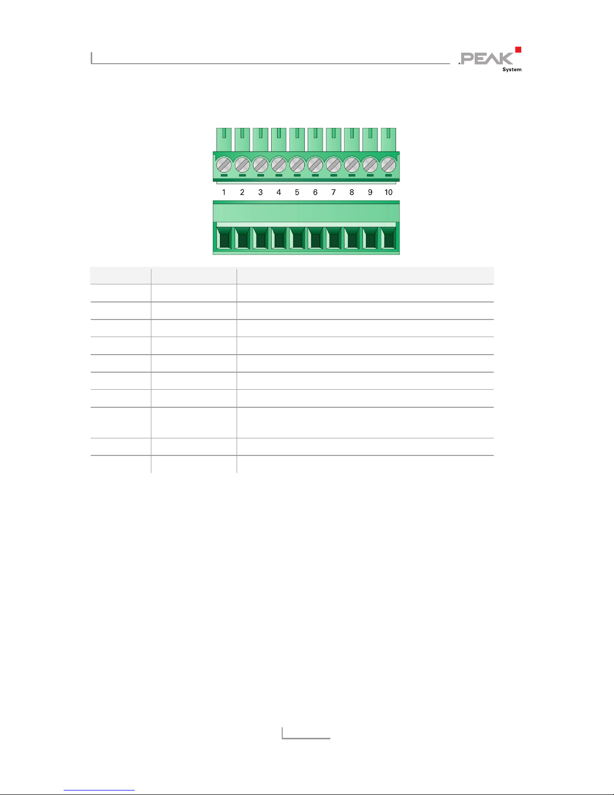
IPEH-002215: one 10-pole screw terminal strip
Besides the primary functions (voltage supply, CAN FD incl. CAN
2.0), there are miscellaneous functions that can be used as needed:
RS-232 interface for serial data transmission
1 I/O pin: digital output, digital input
2 additional digital inputs as an alternative to RS-232 (must be
configured via hardware, see chapter 3 on page 10)
“Boot” input for activation of the CAN bootloader for firmware
upload (see chapter 6 on page 19)
The following subsections describe each connector assignment.
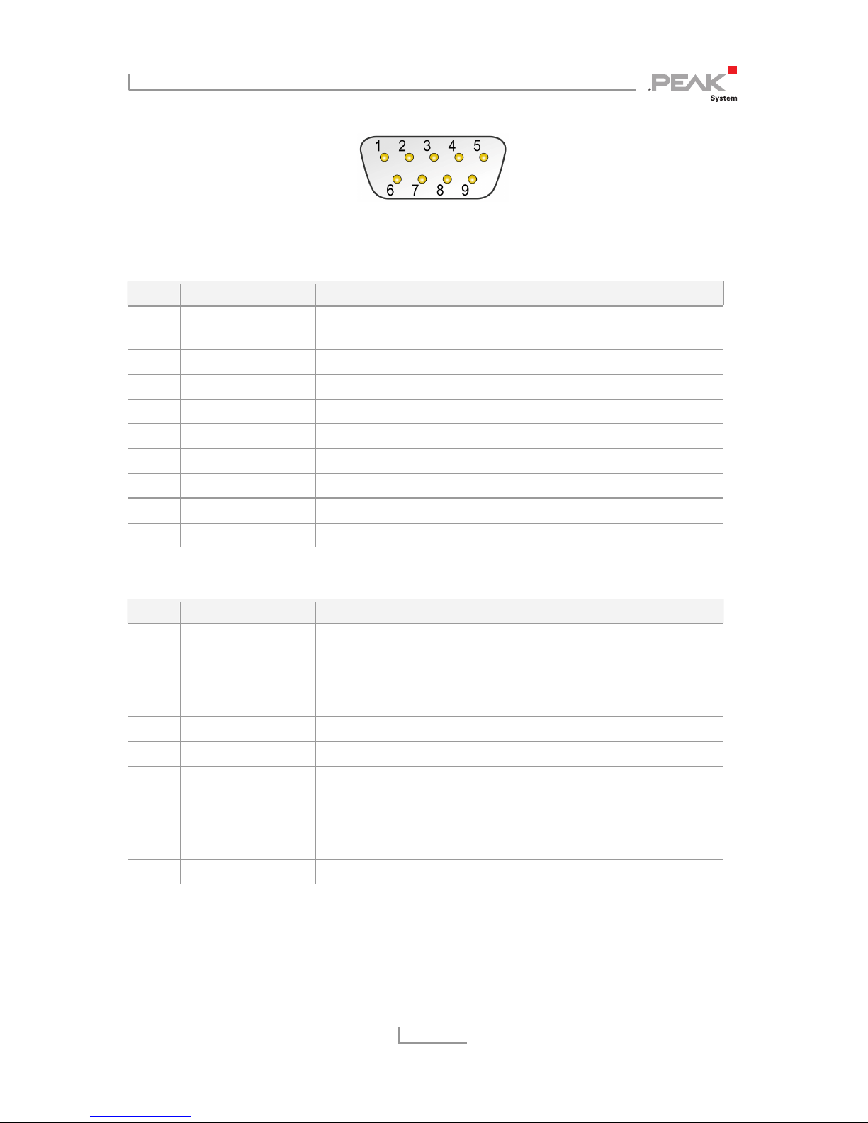
2.1 D-Sub Connectors (IPEH-002214)
The two D-Sub connectors are used for the CAN FD channels CAN1
and CAN2. The CAN lines (CAN_H, CAN_L) are laid out correspon-
ding to the CiA® 303-1 specification.
The power supply of the PCAN-Router FD can be done via both D-
Sub connectors. The supply connections Ub1 and Ub2 are connected
internally in a non-reactive configuration. This means that also
different power sources can be connected.