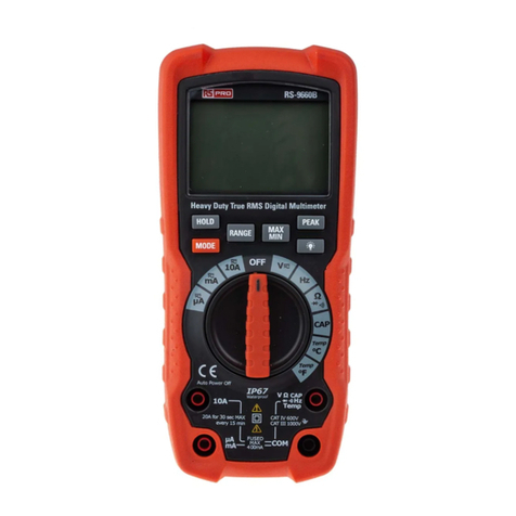
RS PRO RS-9663 User manual

Instruction Manual
RS-9663
Stock No: 161-1626
Heavy Duty True RMS Digital Multimeter
EN
Africa
RS Components SA
P.O. Box 12182,
Vorna Valley, 1686
20 Indianapolis Street,
Kyalami Business Park,
Kyalami, Midrand
South Africa
www.rs-components.com
Asia
RS Components Ltd.
Suite 1601, Level 16, Tower 1,
Kowloon Commerce Centre,
51 Kwai Cheong Road,
Kwai Chung, Hong Kong
www.rs-components.com
China
RS Components Ltd.
Suite 23 A-C
East Sea Business Centre
Phase 2
No. 618 Yan'an Eastern Road
Shanghai, 200001
China
www.rs-components.com
Europe
RS Components Ltd.
PO Box 99, Corby,
Northants.
NN17 9RS
United Kingdom
www.rs-components.com
Japan
RS Components Ltd.
West Tower (12th Floor),
Yokohama Business Park,
134 Godocho, Hodogaya,
Yokohama, Kanagawa 240-0005
Japan
www.rs-components.com
U.S.A
Allied Electronics
7151 Jack Newell Blvd. S.
Fort Worth,
Texas 76118
U.S.A.
www.alliedelec.com
South America
RS Componentes Limitada
Av. Pdte. Eduardo Frei M. 6001-71
Centro Empresas El Cortijo
Conchali, Santiago, Chile
www.rs-components.com

1
Heavy DutyTrue RMS Digital Multimeter / English
16/12/2017 Version No. 001
1. Introduction
This meter measures AC/DC Voltage, AC/DC Current, Resistance, Capacitance, Frequency
(electrical & electronic), Diode Test, and Continuity plus Thermocouple Temperature. It
features a waterproof, rugged design for heavy duty use. Proper use and care of this
meter will provide many years of reliable service.
The symbol adjacent to another symbol, terminal or operating device
indicates that the operator must refer to an explanation in the Operating
Instructions to avoid personal injury or damage to the meter.
WARNING The WARNING symbol indicates a potentially hazardous situation, which
if not avoided, could result in death or serious injury.
CAUTION This CAUTION symbol indicates a potentially hazardous situation, which
if not avoided, may result damage to the product.
The symbol advises the user that the terminal(s) so marked must not be
connected to a circuit point at which the voltage with respect to earth
ground exceeds (in this case) 1000 VAC or VDC.
The symbol adjacent to one or more terminals identifies them as
being associated with ranges that may, in normal use, be subjected to
particularly hazardous voltages. For maximum safety, the meter and its
test leads should not be handled when these terminals are energized.
The symbol indicates that a device is protected throughout by double
insulation or reinforced insulation.
2. Safety

2 3
Input Protection Limits
Function Maximum Input
V DC or V AC 1000 V dc/ac rms
mA AC/DC 800 mA 1000 V fast acting fuse 10 A
A AC/DC 1000 V fast acting fuse (20 A for 30 seconds
max every 15 minutes)
Frequency, Resistance,
Capacitance, Diode Test, Continuity 1000 V dc/ac rms
Temperature 1000 V dc/ac rms
Surge Protection: 8 kV peak per IEC 61010
Heavy DutyTrue RMS Digital Multimeter / EnglishHeavy DutyTrue RMS Digital Multimeter / English
16/12/2017 Version No. 00116/12/2017 Version No. 001
PER IEC1010 OVERVOLTAGE INSTALLATION CATEGORY
OVERVOLTAGE CATEGORY I
Equipment of OVERVOLTAGE CATEGORY I is equipment for connection to circuits in
which measures are taken to limit the transient overvoltages to an appropriate low level.
Note-Examples include protected electronic circuits.
OVERVOLTAGE CATEGORY II
Equipment of OVERVOLTAGE CATEGORY II is energy-consuming equipment to be
supplied from the fixed installation.
Note-Examples include household, office, and laboratory appliances.
OVERVOLTAGE CATEGORY III
Equipment of OVERVOLTAGE CATEGORY III is equipment in fixed installations.
Note-Examples include switches in the fixed installation and some equipment for industrial
use with permanent connection to the fixed installation.
OVERVOLTAGE CATEGORY IV
Equipment of OVERVOLTAGE CATEGORY IV is for use at the origin of the installation.
Note-Examples include electricity meters and primar y over-current protection equipment.
Safety Instructions
This meter has been designed for safe use, but must be operated with caution. The rules
listed below must be carefully followed for safe operation.
1. NEVER apply voltage or current to the meter that exceeds the specified maximum:
2. USE EXTREME CAUTION when working with high voltages.
3. DO NOT measure voltage if the voltage on the "COM" input jack exceeds 1000 V above
earth ground.
4. NEVER connect the meter leads across a voltage source while the function switch is in
the current, resistance, or diode mode. Doing so can damage the meter.
5. ALWAYS discharge filter capacitors in power supplies and disconnect the power when
making resistance or diode tests.
6. ALWAYS turn off the power and disconnect the test leads before opening the covers
to replace the fuse or batteries.
7. NEVER operate the meter unless the back cover, battery and fuse covers are in place
and fastened securely.
8. If the equipment is used in a manner not specified by the manufacturer, the protection
provided by the equipment may be impaired.
3. Controls and Jacks
1. 6,000 counts LCD display
2. MAX/MIN button
3. RANGE button
4. Mode button
5. Function switch
6. mA, μA and 10A input jacks
7. COM input jack
8. Positive input jack
9. HOLD and Backlight button
10. Hz and % button
11. RELATIVE button
Note: Tilt stand and battery compartment
are on the rear of unit.
1
2
6
3
8
9
10
11
4
7
5

4 5
Heavy DutyTrue RMS Digital Multimeter / EnglishHeavy DutyTrue RMS Digital Multimeter / English
16/12/2017 Version No. 00116/12/2017 Version No. 001
5. Operating Instructions
WARNING: Risk of electrocution. High-voltage circuits, both AC and DC, are very
dangerous and should be measured with great care.
1. ALWAYS turn the function switch to the OFF position when the meter is not in use.
2. If “OL” appears in the display during a measurement, the value exceeds the range you
have selected. Change to a higher range.
5-1. DC Voltage Measuments
CAUTION: Do not measure DC voltages if a motor on the circuit is being switched
ON or OFF. Large voltage surges may occur that can damage the meter.
1. Set the function switch to the VDC position.
2. Insert the black test lead banana plug into
the negative COM jack.
Insert the red test lead banana plug into the
positive V jack.
3. Touch the black test probe tip to the
negative side of the circuit.
Touch the red test probe tip to the positive side
of The circuit.
4. Read the voltage in the display.
5-2. AC Voltage (Frequency, Duty Cycle) Measurements
WARNING: Risk of Electrocution. The probe tips may not be long enough to contact
the live parts inside some 240 V outlets for appliances because the contacts are
recessed deep in the outlets. As a result, the reading may show 0 V when the outlet
actually has voltage on it. Make sure the probe tips are touching the metal contacts
inside the outlet before assuming that no voltage is present.
CAUTION: Do not measure AC voltages if a motor on the circuit is being switched ON
or OFF. Large voltage surges may occur that can damage the meter.
1. Set the function switch to the VAC/Hz/% position.
2. Insert the black test lead banana plug into the
negative COM jack.
Insert red test lead banana plug into the positive Vjack.
3. Touch the black test probe tip to the neutral side of
the circuit.
Touch the red test probe tip to the “hot” side of the
circuit.
4. Read the voltage in the display.
5. Press the HZ/% button to indicate “Hz”.
6. Read the frequency in the display.
7. Press the Hz/% button again to indicate “%”.
8. Read the % of duty cycle in the display.

6 7
Heavy DutyTrue RMS Digital Multimeter / EnglishHeavy DutyTrue RMS Digital Multimeter / English
16/12/2017 Version No. 00116/12/2017 Version No. 001
5-3. MV Voltage Measurements 5-4. DC Current Measurements
CAUTION: Do not measure mV voltages if a motor on the circuit is being switched ON
or OFF. Large voltage surges may occur that can damage the meter.
CAUTION: Do not make 20 A current measurements for longer than 30 seconds.
Exceeding 30 seconds may cause damage to the meter and/or the test leads.
1. Set the function switch to the mV position.
2. Press the MODE button to indicate “DC”or “AC ”.
3. Insert the black test lead banana plug into the negative
COM jack.
Insert the red test lead banana plug into the positive Vjack.
4.Touch the black test probe tip to the negative side of the
circuit. Touch the red test probe tip to the positive side of
the circuit.
5.Read the mV voltage in the display.
1. Insert the black test lead banana plug into the negative
COM jack.
2. For current measurements up to 6000 μA DC, set the
function switch to the μA position and insert the red test
lead banana plug into the μA/mA jack.
3. For current measurements up to 600 mA DC, set the
function switch to the mA position and insert the red test
lead banana plug into the μA/mA jack.
4. For current measurements up to 20 A DC, set the
function switch to the 10A/HZ/% position and insert the
red test lead banana plug into the 10 A jack.
5. Press the MODE button to indicate “DC” on the display.
6. Remove power from the circuit under test, then open
up the circuit at the point where you wish to measure
current.
7.Touch the black test probe tip to the negative side of
the circuit.
Touch the red test probe tip to the positive side of the
circuit.
8. Apply power to the circuit.
9. Read the current in the display.

8 9
5-5. AC Current (Frequency, Duty Cycle) Measurements
CAUTION: Do not make 20 A current measurements for longer than 30 seconds.
Exceeding 30 seconds may cause damage to the meter and/or the test leads.
1. Insert the black test lead banana plug into the
negative COM jack.
2. For current measurements up to 6000 μA AC, set
the function switch to the μA position and insert the
red test lead banana plug into the μA/mA jack.
3. For current measurements up to 600 mA AC, set the
function switch to the mA position and insert the red
test lead banana plug into the μA/mA jack.
4. For current measurements up to 20 A AC, set the
function switch to the 10A/HZ/% position and insert
the red test lead banana plug into the 10A jack.
5. Press the MODE button to indicate “AC” on the
display.
6. Remove power from the circuit under test, then open
up the circuit at the point where you wish to measure
current.
7. Touch the black test probe tip to the neutral side of
the circuit.
Touch the red test probe tip to the “hot” side of the
circuit.
8. Apply power to the circuit.
9. Read the current in the display.
10. Press the Hz/% button to indicate “Hz”.
11. Read the frequency in the display.
12. Press the Hz/% button again to indicate “%”.
13. Read the % duty cycle in the display.
14.Press the Hz/% button to return to current
measurement.
8
5-6. Resistance Measurements
WARNING: To avoid electric shock, disconnect power to the unit under test and
discharge all capacitors before taking any resistance measurements. Remove the
batteries and unplug the line cords.
1. Set the function switch to the Ω CAP position.
2. Insert the black test lead banana plug into the negative
COM jack.
Insert the red test lead banana plug into the positive “Ω” jack.
3. Press the MODE button to indicate “Ω” on the display.
4. Touch the test probe tips across the circuit or part under
test. It is best to disconnect one side of the part under test
so the rest of the circuit will not interfere with the resistance
reading.
5. Read the resistance in the display.
Heavy DutyTrue RMS Digital Multimeter / EnglishHeavy DutyTrue RMS Digital Multimeter / English
16/12/2017 Version No. 00116/12/2017 Version No. 001

10 11
5-7. Continuty Check
WARNING: To avoid electric shock, never measure continuity on circuits or wires that
have voltage on them.
1. Set the function switch to the Ω CAP position.
2. Insert the black lead banana plug into the negative COM jack.
Insert the red test lead banana plug into the positive Ωjack.
3. Press the MODE button to indicate “ ” and “Ω” on the display
4. Touch the test probe tips to the circuit or wire you wish to check.
5. If the resistance is less than approximately 35Ω, the audible signal will sound. If the
circuit is open, the display will indicate “OL”.
5-8. Diode Test
1. Set the function switch to the Ω CAP position.
2. Insert the black test lead banana plug into the negative COM jack and the red test lead
banana plug into the positive Vjack.
3. Press the MODE button to indicate and Von the display.
4. Touch the test probes to the diode under test.
Forward voltage will typically indicate 0.400 to 0.700 V. Reverse voltage will indicate
“OL”.
Shorted devices will indicate near 0 V and an open device will indicate “OL” in both
polarities.
Heavy DutyTrue RMS Digital Multimeter / EnglishHeavy DutyTrue RMS Digital Multimeter / English
16/12/2017 Version No. 00116/12/2017 Version No. 001

12 13
5-9. Temperature Measurements
1. Set the function switch to the Temp position.
2. Insert the Temperature Probe into the input jacks,
making sure to observe the correct polarity.
3. Press the MODE button to indicate ºF or ºC
4. Touch the Temperature Probe head to the part whose
temperature you wish to measure. Keep the probe
touching the part under test until the reading stabilizes
(about 30 seconds).
5. Read the temperature in the display.
Note: The temperature probe is fitted with a type K mini
connector. A mini connector to banana connector adaptor
is supplied for connection to the input banana jacks.
8
5-10. Capacitance Measurements
WARNING: To avoid electric shock, disconnect power to the unit under est and
discharge all capacitors before taking any capacitance measurements. Remove the
batteries and unplug the line cords.
1. Set the rotary function switch to the Ω CAP
position.
2. Insert the black test lead banana plug into the negative
COM jack.
Insert the red test lead banana plug into the positive V
jack.
3. Press the MODE button to indicate “nF” on the
display.
4. Touch the test leads to the capacitor to be tested.
5. The test may take up to 3 minutes or more for large
capacitors to charge. Wait until the readings settle before
ending the test.
6. Read the capacitance value in the display
5-11. Frequency/Duty Cycle Measurements (Electronic)
1. Set the rotary function switch to the “Hz%” position.
2. Press the Hz/% button to indicate “Hz” in the display.
3. Insert the black lead banana plug into the negative COM
jack and the red test lead banana plug into the positive Hz
jack.
4. Touch the test probe tips to the circuit under test.
5. Read the frequency on the display.
6. Press the Hz/% button again to indicate “%” on the
display.
7. Read the % of duty cycle on the display.
5-12. Autoranging/Manual Range Selection
When the meter is first turned on, it automatically goes into Autoranging.
This automatically selects the best range for the measurements being made and is
generally the best mode for most measurements. For measurement situations requiring
that a range be manually selected, perform the following:
1. Press the RANGE key. The “AUTO” display indicator will turn off.
2. Press the RANGE key to step through the available ranges until you select the range
you want.
3. To exit the Manual Ranging mode and return to Autoranging, press and hold the RANGE
key for 2 seconds.
Note: Manual ranging does not apply for the Capacitance and Frequency functions.
Heavy DutyTrue RMS Digital Multimeter / EnglishHeavy DutyTrue RMS Digital Multimeter / English
16/12/2017 Version No. 00116/12/2017 Version No. 001

14 15
5-13. MAX/MIN
Note: When using the MAX/MIN function in Autoranging mode, the meter will “lock” into
the range that is displayed on the LCD when MAX/MIN is activated. If a MAX/Min reading
exceeds that range, an “OL” will be displayed. Select the desired range BEFORE entering
MAX/MIN mode.
1. Press the MAX/MIN key to activate the MAX/MIN recording mode. The display icon
"MAX" will appear. The meter will display and hold the maximum reading and will update
only when a new “max” occurs.
2.Press the MAX/MIN key again and the display icon "MIN" will appear. The meter will
display and hold the minimum reading and will update only when a new “min” occurs.
3.To exit MAX/MIN mode press and hold the MAX/MIN key for 2 seconds.
5-14. REL Function
The REL Function allows a reference value measurement to balance possible line losses
such with resistance measurements or residue magnetism of the current sensor. For this
purpose, the current indicated value is set to zero. A new reference value is set.
Press the REL key to activate this measuring function. “REL” appears on the display.
In order to deactivate this function, press the REL key again and the REL display will
disappear.
5-15. Display Backlight
Press the HOLD key for >1 second to turn on or off the display backlight function.
5-16. HOLD
The hold function freezes the reading in the display. Press the HOLD key momentarily to
activate or to exit the HOLD function.
5-17. AUTO Power Off
The auto off feature will turn the meter off after 15 minutes. To disable the auto
power off feature, hold down the MODE button and turn the meter on.
5-18. LOW Battery Indication
The icon will appear in the lower left conner of the display when the battery voltage
becomes low. Replace the battery when this appears.
6. Maintenance
WARNING: To avoid electric shock, disconnect the test leads from any source of
voltage before removing the back cover or the battery or fuse covers.
WARNING: To avoid electric shock, disconnect the test leads from any source of
voltage before removing the battery cover.
WARNING: To avoid electric shock, do not operate the meter until the battery cover
is in place and fastened securely.
WARNING: To avoid electric shock, do not operate your meter until the battery and
fuse covers are in place and fastened securely.
This MultiMeter is designed to provide years of dependable service, if the following care
instructions are performed:
1. KEEP THE METER DRY. If it gets wet, wipe it off.
2. USE AND STORE THE METER IN NORMAL TEMPERATURES. Temperature
extremes can shorten the life of the electronic parts and distort or melt plastic parts.
3. HANDLE THE METER GENTLY AND CAREFULLY. Dropping it can damage the
electronic parts or the case.
4. KEEP THE METER CLEAN. Wipe the case occasionally with a damp cloth. DO NOT
use chemicals, cleaning solvents, or detergents.
5. USE ONLY FRESH BATTERIES OF THE RECOMMENDED SIZE AND TYPE.
Remove old or weak batteries so they do not leak and damage the unit.
6. IF THE METER IS TO BE STORED FOR A LONG PERIOD OF TIME, the batteries
should be removed to prevent damage to the unit.
6-1. Battery Installation
1. Turn the power off and disconnect the test leads from the meter.
2. Open the rear battery cover by removing the screw using a Phillips head screwdriver.
3. Insert the battery into battery holder, observing the correct polarity.
4. Put the battery cover back in place. Secure with the screw.
NOTE: If your meter does not work properly, check the fuses and batteries to make sure
that they are still good and that they are properly inserted.
Heavy DutyTrue RMS Digital Multimeter / EnglishHeavy DutyTrue RMS Digital Multimeter / English
16/12/2017 Version No. 00116/12/2017 Version No. 001
16 17
7. Specications
Heavy DutyTrue RMS Digital Multimeter / English
16/12/2017 Version No. 001
Function Range Resolution Accuracy
DC Voltage
600 mV 0.1 mV ±(0.8% reading + 5 digits)
6 V 0.001 V
±(0.5% reading + 3 digits)60 V 0.01 V
600 V 0.1 V
1000 V 1 V ±(0.8% reading + 5 digits)
AC Voltage
45 Hz to 1 kHz
600 mV 0.1 mV
±(1.5% reading + 8 digits)
6 V 0.001 V
60 V 0.01 V
600 V 0.1 V
1000 V 1V ±(1.2% reading + 5 digits)
All AC voltage ranges are specified from 5% of range to 100% of range
Function Range Resolution Accuracy
DC Current
600 μA 0.1 μA
±(1.0% reading + 3 digits)
6000 μA 1 μA
60 mA 0.01 mA
600 mA 0.1 mA
6 A 0.001A ±(1.5% reading + 3 digits)
10 A 0.01 A
(20 A: 30 seconds max with reduced accuracy)
AC Current
45 Hz to 1 kHz
600 μA 0.1 μA
±(1.5% reading + 3 digits)
6000 μA 1 μA
60 mA 0.01 mA
600 mA 0.1 mA
6 A 0.001 A ±(2.0% reading + 5 digits)
10 A 0.01 A
(20 A: 30 seconds max with reduced accuracy)
All AC Cur rent ranges are specified from 5% of range to 100% of
range
NOTE: Accuracy is stated at 18°C to 28°C (65°F to 83°F) and less than 75% RH
Function Range Resolution Accuracy
Resistance
600 Ω 0.1 Ω
±(1.2% reading + 5 digits)
6k Ω 0.001 kΩ
60 kΩ 0.01 kΩ
600 kΩ 0.1 kΩ
6M Ω 0.001 MΩ
60 MΩ 0.01 MΩ ±(2% reading + 20 digits)
Heavy DutyTrue RMS Digital Multimeter / English
16/12/2017 Version No. 001
6-2. Replacing the Fuses
WARNING: To avoid electric shock, disconnect the test leads from any source of
voltage before removing the fuse cover.
WARNING: To avoid electric shock, do not operate your meter until the fuse cover is
in place and fastened securely.
1. Disconnect the test leads from the meter.
2. Remove the battery cover.
3. Gently remove the old fuse and install the new fuse into the holder.
4. Always use a fuse of the proper size and value (0.8 A/1000 V fast blow for the 600 mA
range [SIBA 70-172-40], 10 A/1000 V fast blow for the 20 A range [SIBA 50-199-06]).
5. Replace and secure the rear cover, battery and battery cover.

18 19
Heavy DutyTrue RMS Digital Multimeter / English
16/12/2017 Version No. 001
Heavy DutyTrue RMS Digital Multimeter / English
16/12/2017 Version No. 001
Function Range Resolution Accuracy
Capacitance
40 nF 0.01 nF ±(5.0% reading + 10 digits)
400 nF 0.1 nF
±(3.0% reading + 5 digits)
4 μF 0.001 μF
40 μF 0.01 μF
400 μF 0.1 μF
4000 μF 1 μF ±(5% reading + 10 digits)
Frequency
(electronic)
9.999 Hz 0.001Hz
±(0.1% reading + 5 digits)
99.99 Hz 0.01 Hz
999.9 Hz 0.1 Hz
9.999 kHz 0.001 kHz
99.99 kHz 0.01 kHz
999.9 kHz 0.1 kHz
9.999 MHz 0.001 MHz
Frequency
(electrical)
10 - 400 Hz 0.01Hz ±(0.5% reading)
Sensitivity: 15 V rms
Duty Cycle 0.1 to 99.9% 0.1% ±(1.2% reading + 2 digits)
Pulse width: 100 μs - 100 ms, Frequency: 5 Hz to 150 kHz
Temp
(type-K)
-50 to 1382°F 0.1°F ±(3.0% reading + 5°C/ 9°F
digits) (probe accuracy not
included)
-45 to 750°C 0.1°C
Note: Accuracy specifications consist of two elements:
• (% reading) – This is the accuracy of the measurement circuit.
• (+ digits) – This is the accuracy of the analogue to digital converter.
Enclosure Double molded, waterproof
Shock (Drop Test) 6.5 ft. (2 meters)
Diode Test Test current of 0.9 mA maximum, open circuit voltage 2.8
V dc typical
Continuity Check Audible signal will sound if the resistance is less than 35
Ω (approx.), test current <0.35 mA
Temperature Sensor Requires type K thermocouple
Input Impedance >10 M Ω V dc & >10 M Ω V ac
AC Response Averaging
ACV Bandwidth 45 Hz to 1 kHz
Crest Factor ≤3 at full scale up to 500 V, decreasing linearly to ≤1.5
at 1000 V
Display 6,000 counts backlit liquid crystal with bargraph
Overrange Indication “OL” is displayed
Auto Power Off 15 minutes (approximately) with disable feature
Polarity Automatic (no indication for positive); Minus (-) sign for
negative
Measurement Rate 2 times per second, nominal
Low Battery Indication “” is displayed if battery voltage drops below operating
voltage
Battery One 9 V (NEDA 1604) battery
Fuses mA, μA ranges; 0.8 A/1000 V ceramic fast blow A range;
10 A/1000 V ceramic fast blow
Operating Temperature 5°C to 40°C (41°F to 104°F)
Storage Temperature -20°C to 60°C (-4°F to 140°F)
Operating Humidity Max 80% up to 31°C (87°F) decreasing linearly to 50%
at 40°C (104°F)
Storage Humidity <80%
Operating Altitude 7000 ft. (2000 meters) maximum.
Weight 436 g (includes holster).
Size (182 x 82 x 59 mm) (includes holster)
Safety
This meter is intended for origin of installation use and
protected, against the users, by double insulation per
EN61010-1 and IEC61010-1 2nd Edition (2001) to Category
IV 600V and Category III 1000V; Pollution Degree 2. The
meter also meets UL 61010-1, 2nd Edition (2004), CAN/
CSA C22.2 No. 61010-1 2nd Edition (2004), and UL
61010B-2-031, 1st Edition (2003)

1
Manuel d'instructions
RS-9663
No d'inventaire: 161-1626
Multímetro digital verdadero RMS
FR
16/12/2017 Version No. 001
Multímetro digital verdadero RMS / Francais
1. Introducción
Este medidor mide el voltaje de AC / DC, la corriente de AC / DC, la resistencia, la
capacitancia, la frecuencia (eléctrica y electrónica), la prueba de diodo y la continuidad
más la temperatura del termopar. Cuenta con un diseño resistente al agua y resistente
para uso intensivo. El uso y el cuidado adecuados de este medidor proporcionarán muchos
años de servicio confiable.
El símbolo adyacente a otro símbolo, terminal o dispositivo operativo
indica que el operador debe consultar una explicación en las Instrucciones
de funcionamiento para evitar lesiones personales o daños en el medidor.
WARNING El símbolo de ADVERTENCIA indica una situación potencialmente
peligrosa que, de no evitarse, podría provocar la muerte o lesiones graves.
CAUTION Este símbolo de PRECAUCIÓN indica una situación potencialmente
peligrosa que, de no evitarse, puede dañar el producto.
El símbolo informa al usuario que los terminales así marcados no deben
conectarse a un punto de circuito en el que la tensión con respecto a la
tierra excede (en este caso) 1000 VCA o VDC.
El símbolo adyacente a uno o más terminales los identifica como
asociados con rangos que pueden, en uso normal, estar sujetos a voltajes
particularmente peligrosos. Para una seguridad máxima, el medidor y sus
cables de prueba no deben manipularse cuando estos terminales están
energizados.
El símbolo indica que un dispositivo está protegido por doble aislamiento
o aislamiento reforzado.
2. Seguridad

2 3
16/12/2017 Version No. 00116/12/2017 Version No. 001
Multímetro digital verdadero RMS / FrancaisMultímetro digital verdadero RMS / Francais
Límites de protección de entrada
Funcion Maximasentradas
V DC or V AC 1000 V dc/ac rms
mA AC/DC Fusible de acción rápida 800 mA 1000 V 10 A
A AC/DC Fusible de acción rápida de 1000 V (20 A por
30 segundos como máximo cada 15 minutos)
Frecuencia, Resistencia, Capacitancia,
Prueba de diodo, Continuidad 1000 V dc/ac rms
TemperaturaProtección contra 1000 V dc/ac rms
sobretensiones: pico de 8 kV según IEC 61010
POR IEC1010, INSTALACIÓN DE CATEGORÍA CONTRA SOBRETENSIONES,
VOLTAJE CATEGORÍA I
El equipo de CATEGORÍA DE SOBRETENSIÓN I es un equipo para la conexión a circuitos
en el que se toman medidas para limitar las sobretensiones transitorias a un nivel bajo
apropiado.
Nota: los ejemplos incluyen circuitos electrónicos protegidos.
CATEGORÍA DE SOBRETENSIÓN II
El equipo de CATEGORÍA DE SOBRETENSIÓN II es un equipo que consume energía para
ser suministrado desde la instalación fija.
Nota: los ejemplos incluyen electrodomésticos, oficinas y electrodomésticos de
laboratorio.
CATEGORÍA DE SOBRETENSION III
El equipo de CATEGORÍA DE SOBRETENSIÓN III es un equipo en instalaciones fijas.
Nota: los ejemplos incluyen interruptores en la instalación fija y algunos equipos para uso
industrial con conexión permanente a la instalación fija.
CATEGORÍA DE SOBRETENSIÓN IV
El equipo de CATEGORÍA DE SOBRETENSIÓN IV se usa en el origen de la instalación.
Nota: los ejemplos incluyen medidores de electricidad y equipo primario de protección
contra sobrecorriente.
Instrucciones de seguridad
Este medidor ha sido diseñado para un uso seguro, pero debe ser operado con precaución. Las
reglas enumeradas a continuación se deben seguir cuidadosamente para una operación segura.
1. NUNCA aplique voltaje o corriente al medidor que exceda el máximo especificado:
2. USE EXTREMA PRECAUCIÓN cuando trabaje con altos voltajes.
3. NO mida el voltaje si el voltaje en la toma de entrada "COM" excede los 1000 V sobre
la conexión a tierra.
4. NUNCA conecte los cables del medidor a través de una fuente de voltaje mientras el
interruptor de función esté en modo de corriente, resistencia o diodo. Hacerlo puede
dañar el medidor.
5. SIEMPRE descargue los condensadores del filtro en las fuentes de alimentación y
desconecte la alimentación cuando realice pruebas de resistencia o diodos.
6. SIEMPRE apague la alimentación y desconecte los cables de prueba antes de abrir las
cubiertas para reemplazar el fusible o las baterías.
7. NUNCA opere el medidor a menos que la cubierta posterior, la batería y las cubiertas
de los fusibles estén en su lugar y bien sujetos.
8. Si el equipo se utiliza de una manera no especificada por el fabricante, la protección
proporcionada por el equipo puede verse afectada.
3. Controlesy Jacks
1. Pantalla LCD6,000 cuentas
2. Botón MAX / MIN
3. botón RANGE
4. Botón de modo
5. funciónInterruptor
6. Tomas de entrada de mA, μA y 10A
7. Toma de entrada COM
8. Toma de entradapositiva
9. Botón HOLD y el BotónBacklight
10. Botón Hz y el Botón %
11. Botón RELATIVO
Nota: El soporte inclinable y el compartimento
de la batería se encuentran en la parte posterior
de la unidad.
1
2
6
3
8
9
10
11
4
7
5

4 5
16/12/2017 Version No. 00116/12/2017 Version No. 001
Multímetro digital verdadero RMS / FrancaisMultímetro digital verdadero RMS / Francais
5. Instrucciones de funcionamiento
ADVERTENCIA: Riesgo de electrocución. Los circuitos de alto voltaje, tanto AC
como DC, son muy peligrosos y deben medirse con mucho cuidado.
1. SIEMPRE coloque el selector de función en la posición OFF cuando el medidor no esté
en uso.
2. Si aparece "OL" en la pantalla durante una medición, el valor excede el rango que ha
seleccionado. Cambiar a un rango más alto.
5-1. Mediciones de voltaje DC
ADVERTENCIA: No mida voltajes de DC si un motor en el circuito se enciende o se
apaga. Pueden ocurrir grandes sobretensiones que pueden dañar el medidor.
1. Ajuste el interruptor de función en la
posición VDC.
2. Inserte el conector banana del cable negro
de prueba en el enchufe negativo COM.
Inserte el conector banana del cable de
prueba rojo en el conector positivo en V.
3. Toque la punta de la sonda de prueba negra
en el lado negativo del circuito.
Toque la punta de la sonda de prueba roja en
el lado positivo del circuito.
4. Lea el voltaje en la pantalla.
5-2. Mediciones de voltaje AC (frecuencia, ciclo de trabajo)
ADVERTENCIA: Riesgo de electrocución Las puntas de las sondas pueden no ser lo
suficientemente largas como para entrar en contacto con las partes activas dentro de
algunas tomas de corriente de 240 V para los electrodomésticos porque los contactos
están empotrados en las profundidades de las salidas. Como resultado, la lectura
puede mostrar 0 V cuando la salida tiene voltaje. Asegúrese de que las puntas de la
sonda toquen los contactos metálicos dentro de la salida antes de suponer que no hay
voltaje presente.
ADVERTENCIA: No mida voltajes de AC si un motor en el circuito se enciende o se
apaga. Pueden ocurrir grandes sobretensiones que pueden dañar el medidor.
1. Ajuste el selector de función en la posición VAC / Hz /%.
2. Inserte el conector banana del cable negro de prueba
en el enchufe negativo COM.
Inserte el conector banana del cable rojo de prueba en
el conector positivo en V.
3. Toque la punta de la sonda de prueba negra en el lado
neutral del circuito.
Toque la punta de la sonda de prueba roja en el lado
"caliente" del circuito.
4. Lea el voltaje en la pantalla.
5. Presione el botón HZ /% para indicar "Hz".
6. Lea la frecuencia en la pantalla.
7. Presione el botón Hz /% nuevamente para indicar "%".
8. Lea el% del ciclo de trabajo en la pantalla.

6 7
16/12/2017 Version No. 00116/12/2017 Version No. 001
Multímetro digital verdadero RMS / FrancaisMultímetro digital verdadero RMS / Francais
5-3. Mediciones de voltaje MV
ADVERTENCIA: No mida voltajes mV si un motor en el circuito se enciende o se
apaga. Puedenocurrirgrandessobretensionesquepuedendañar el medidor.
1. Ajuste el interruptor de función en la posición mV.
2. Presione el botón MODE para indicar "DC" o "AC".
3. Inserte el conector banana del cable negro de prueba en
el enchufe negativo COM.
Inserte el conector banana del cable de prueba rojo en el
conector positivo en V.
4.Toque la punta de la sonda de prueba negra en el lado
negativo del circuito. Toque la punta de la sonda de
prueba roja en el lado positivo del circuito.
5.Lea la tensión de mV en la pantalla.
5-4. Mediciones de corrienteDC
ADVERTENCIA: No realice mediciones de corriente de 20 A durante más de 30
segundos. Exceder los 30 segundos puede dañar el medidor y / o los cables de prueba.
1. Inserte el conector banana del cable negro de prueba
en el enchufe negativo COM.
2. Para mediciones de corriente de hasta 6000 μA DC,
coloque el interruptor de función en la posición μA e
inserte el conector banana del cable de prueba rojo en
la toma μA / mA.
3. Para mediciones de corriente de hasta 600 mA DC,
coloque el interruptor de función en la posición mA e
inserte el conector banana del cable de prueba rojo en
la toma μA / mA.
4. Para medidas de corriente de hasta 20 A CC, coloque el
interruptor de función en la posición 10A / HZ /% e
inserte el conector banana del cable de prueba rojo en
la toma de 10 A.
5. Presione el botón MODE para indicar "DC" en la
pantalla.
6. Retire la energía del circuito bajo prueba, luego abra el
circuito en el punto donde desea medir la corriente.
7. Toque la punta de la sonda de prueba negra en el lado
negativo del circuito.
Toque la punta de la sonda de prueba roja en el lado
positivo del circuito.
8. Aplicar potencia al circuito.
9. Lee la corriente en la pantalla.

8 9
16/12/2017 Version No. 00116/12/2017 Version No. 001
Multímetro digital verdadero RMS / FrancaisMultímetro digital verdadero RMS / Francais
5-5. Mediciones de corriente AC (frecuencia, ciclo de trabajo)
ADVERTENCIA: No realice mediciones de corriente de 20 A durante más de 30
segundos. Exceder los 30 segundos puede dañar el medidor y / o los cables de prueba.
1. Inserte el conector banana del cable negro de prueba
en el enchufe negativo COM.
2. Para mediciones de corriente de hasta 6000μA de
CA, coloque el interruptor de función en la posición
μA e inserte el conector banana del cable de prueba
rojo en la toma μA / mA.
3. Para mediciones de corriente de hasta 600 mA CA,
coloque el interruptor de función en la posición mA e
inserte el conector banana del cable de prueba rojo
en la toma μA / mA.
4. Para mediciones de corriente de hasta 20 A CA,
configure el interruptor de función en la posición
10A/HZ /% e inserte el conector banana del cable de
prueba rojo en la toma 10 A.
5. Presione el botón MODE para indicar "AC" en la
pantalla.
6. Retire la energía del circuito bajo prueba, luego abra
el circuito en el punto donde desea medir la corriente.
7. Toque la punta de la sonda de prueba negra en el
lado neutral del circuito. Toque la punta de la sonda
de prueba roja en el lado "caliente" del circuito.
8
8. Aplicar potencia al circuito.
9.Lea la corriente en la pantalla.
10. Presione el botón Hz /% para indicar "Hz".
11. Lea la frecuencia en la pantalla.
12. Presione el botón Hz /% nuevamente para indicar "%".
13. Lea el% de ciclo de trabajo en la pantalla.
14. Presione el botón Hz /% para volver a la medición actual.
5-6. MEDIDAS DE RESISTENCIA
ADVERTENCIA: Para evitar descargas eléctricas, desconecte la energía a la unidad
bajo prueba y descargue todos los condensadores antes de tomar cualquier medida de
resistencia. Retire las baterías y desenchufe los cables de línea.
1. Ajuste el interruptor de función Ω CAP posición.
2. Inserte el conector banana del cable negro de prueba en el
enchufe negativo COM.
Inserte el conector banana del cable de prueba rojo en el
enchufe positivo "Ω".
3. Presione el botón MODE para indicar "Ω" en la pantalla.
4. Toque las puntas de la sonda de prueba a través del circuito
o parte bajo prueba. Lo mejor es desconectar un lado de la
pieza bajo prueba para que el resto del circuito no interfiera
con la lectura de resistencia.
5. Lea la resistencia en la pantalla.

10 11
16/12/2017 Version No. 00116/12/2017 Version No. 001
Multímetro digital verdadero RMS / FrancaisMultímetro digital verdadero RMS / Francais
5-7. Pruebade continuidad
ADVERTENCIA: Para evitar descargas eléctricas, nunca mida la continuidad en
circuitos y cables que tengan voltaje sobre ellos.
1. Ajuste el interruptor de función en la posición Ω CAP .
2. Inserte el conector banana de plomo negro en el enchufe negativo COM. Inserte el
conector banana del cable de prueba rojo en el enchufe positivo Ω.
3. Presione el botón MODE para indicar “ ” y "Ω" en la pantalla.
4. Toque las puntas de la sonda de prueba al circuito o cable que desea verificar.
5. Si la resistencia es inferior a aproximadamente 35 Ω, sonará la señal audible. Si el
circuito está abierto, la pantalla indicará "OL".
5-8. Prueba de diodo
1. Ajuste el interruptor de función en la posición Ω CAP .
2. Inserte el conector banana del cable de prueba negro en el enchufe negativo COM y el
conector banana del cable rojo de prueba en el enchufe positivo V.
3. Presione el botón MODE para indicar y V en la pantalla.
4. Toque las sondas de prueba al diodo bajo prueba. El voltaje hacia delante generalmente
indicará 0.400 a 0.700 V. El voltaje inverso indicará "OL". Los dispositivos en corto
indicarán cerca de 0V y un dispositivo abierto indicará "OL" en ambas polaridades.

12 13
16/12/2017 Version No. 00116/12/2017 Version No. 001
Multímetro digital verdadero RMS / FrancaisMultímetro digital verdadero RMS / Francais
5-9. Température
1. Réglez le commutateur en position Temp.
2. Insérez la sonde de température dans les prises d'entrée,
en veillant à respecter la polarité .
3. Appuyez sur le bouton MODE pour indiquer ºF ou ºC.
4. Touchez la tête de la sonde de température de la partie
dont vous souhaitez mesurer la température. Maintenez
la sonde en contact avec la pièce à tester jusqu'à ce
que la lecture se stabilise (environ 30 secondes).
5. Lisez la température sur l'affichage.
Remarque: La sonde de température est équipée d'un
connecteur mini type K. Un mini connecteur à l'adaptateur
de connecteur banane est fourni pour la connexion à des
prises bananes d'entrée.
8
5-10. Capacitance
AVERTISSEMENT: Pour éviter les chocs électriques, déconnectez l'alimentation de
l'unité testée et déchargez tous les condensateurs avant de prendre des mesures de
capacité. Retirez les piles et débranchez les cordons .
1. Réglez le commutateur rotatif en position Ω CAP.
2. Insérez la fiche banane du fil noir dans la prise COM
négative.
Insérez la fiche banane du fil rouge dans la prise V
positive.
3. Appuyez sur le bouton MODE pour indiquer "nF" sur
l'écran.
4. Touchez les cordons sur le condensateur à tester.
5. Le test peut prendre jusqu'à 3 minutes ou plus pour
charger de grands condensateurs. Attendez que les
lectures se terminent avant de terminer le test.
6. Lire la valeur de capacité sur l’écran.
5-11. Fréquences / mesures du cycle de service
(électronique)
1. Réglez le commutateur rotatif en position "Hz%".
2. Appuyez sur le bouton Hz /% pour indiquer "Hz" sur
lécran.
3. Insérez la fiche banane noire dans la prise COM
négative et la fiche banane rouge dans la prise Hz
positive.
4. Touchez les pointes de la sonde au circuit testé.
5. Lisez la fréquence sur l'écran.
6. Appuyez de nouveau sur le bouton Hz /% pour
indiquer "%" sur l'écran.
7. Lisez le% du cycle de service sur l'écran.
5-12. Sélection automatique de gamme / manuelle
Lorsque le lecteur est allumé pour la première fois, il passe automatiquement en mode
automatique.
Ceci sélectionne automatiquement la meilleure gamme pour les mesures effectuées
et généralement le meilleur mode pour la plupart des mesures. Pour les situations
nécessitant la sélection manuelle d'une gamme, procédez comme suit:
1. Appuyez sur la touche RANGE. L'indicateur "AUTO" s'éteint.
2. Appuyez sur la touche RANGE pour parcourir les gammes disponibles jusqu'à ce que
vous sélectionniez la gamme souhaitée.
3. Pour quitter le mode de télémétrie manuelle et revenir à la gamme automatique,
maintenez la touche RANGE enfoncée pendant 2 secondes.
Remarque: La portée manuelle ne s'applique pas aux fonctions Capacitance et Fréquence.

14 15
16/12/2017 Version No. 00116/12/2017 Version No. 001
Multímetro digital verdadero RMS / FrancaisMultímetro digital verdadero RMS / Francais
5-13. MAXIMUM MINIMUM
Remarque: Lorsque vous utilisez la fonction MAX / MIN en mode Autoranging, l'appareil
se verrouille dans la gamme affichée sur l'écran LCD lorsque MAX / MIN est activé. Si une
lecture MAX / Min dépasse cette gamme, un "OL" sera affiché. Sélectionnez la gamme
désirée AVANT d'entrer dans le mode MAX / MIN.
1. Appuyez sur la touche MAX / MIN pour activer le mode d'enregistrement MAX / MIN.
L'icône d'affichage "MAX" apparaît. Le compteur affichera et maintiendra la lecture
maximale et ne se mettra à jour que lorsqu'un nouveau "max" aura lieu.
2. Appuyez à nouveau sur la touche MAX / MIN et l'icône d'affichage "MIN" apparaîtra.
Le compteur affichera et maintiendra la lecture minimale et ne se mettra à jour que
lorsqu'un nouveau "MIN" se produit.
3. Pour quitter le mode MAX / MIN, appuyez sur la touche MAX / MIN et maintenez-la
enfoncée pendant 2 secondes.
5-14. Fonction REL
La fonction REL permet d'effectuer une mesure de la valeur de référence afin d'équilibrer
les pertes de ligne possibles, telles que les mesures de résistance ou le magnétisme
résiduel du capteur de courant. A cet effet, la valeur actuelle indiquée est mise à zéro. Une
nouvelle valeur de référence est définie.
Appuyez sur la touche REL pour activer cette fonction . "REL" apparaît sur l'écran.
Pour désactiver cette fonction, appuyez à nouveau sur la touche REL et l'affichage REL
disparaîtra.
5-15. Afcher le rétro-éclairage
Appuyez sur la touche HOLD pendant plus une seconde pour activer ou désactiver la
fonction de rétroéclairage sur l'écran.
5-16. La fonction HOLD
La fonction de maintien gèle la lecture sur l'écran. Appuyer brièvement sur la touche HOLD
pour activer ou quitter la fonction HOLD.
5-17. Arrêt automatique
La fonction d'extinction automatique éteindra l'appareil après 15 minutes. Pour désactiver
la fonction de mise hors tension automatique, maintenez le bouton MODE enfoncé et
allumez le lecteur.
5-18. Indication de batterie faible
L'icône apparaîtra dans le coin inférieur gauche de l'écran lorsque la tension de la
batterie devient faible. Remplacez la batterie lorsque cela apparaît.
6. Entretien
AVERTISSEMENT: Pour éviter les chocs électriques, déconnectez les cordons de
toute source de tension avant de retirer le couvercle arrière ou la batterie ou les
couvercles des fusibles.
AVERTISSEMENT: Pour éviter les chocs électriques, ne faites pas fonctionner votre
lecteur tant que les couvercles des piles et des fusibles ne sont pas en place et bien fixés.
Ce multimètre est conçu pour fournir des années de service fiable, si les instructions
d'entretien suivantes sont effectuées:
1. GARDEZ LE COMPTEUR SEC. S'il est mouillé, essuyez-le.
2. UTILISER ET STOCKER LE COMPTEUR DANS DES TEMPÉRATURES NORMALES.
Les températures extrêmes peuvent raccourcir la durée de vie des pièces électroniques et
fausser ou faire fondre les pièces en plastique.
3. MANIPULEZ LE COMPTEUR DOUCEMENT ET ATTENTIVEMENT. Le laisser tomber
peut endommager les pièces électroniques ou le boîtier.
4. MAINTENEZ LE MÈTRE PROPRE. Essuyez le boîtier de temps en temps avec un
chiffon humide. N'utilisez PAS de produits chimiques, de solvants de nettoyage ou de
détergents.
5. UTILISEZ UNIQUEMENT DES PILES FRAÎCHES DE LA TAILLE ET DU TYPE
RECOMMANDÉS.
Retirez les piles usagées ou faibles afin qu'elles ne fuient pas et n'endommagent pas
l'appareil.
6. SI LE COMPTEUR DOIT ÊTRE STOCKÉ PENDANT UNE LONGUE PÉRIODE, les
piles doivent être retirées pour éviter d'endommager l'appareil.
AVERTISSEMENT: TPour éviter les chocs électriques, débranchez les cordons de
toute source de tension avant de retirer le couvercle de la batterie.
6-1. Installation de la batterie

16 17
16/12/2017 Version No. 00116/12/2017 Version No. 001
Multímetro digital verdadero RMS / FrancaisMultímetro digital verdadero RMS / Francais
AVERTISSEMENT: Pour éviter les chocs électriques, n'utilisez pas le lecteur tant que
le couvercle des piles n'est pas en place et bien fixé.
1. Mettez l'appareil hors tension et déconnectez les cordons du multimètre.
2. Ouvrez le couvercle de la batterie arrière en retirant la vis à l'aide d'un tournevis
cruciforme.
3. Insérez la batterie dans le porte-batterie en respectant la polarité.
4. Remettez le couvercle de la batterie en place. Fixez avec la vis.
REMARQUE: Si votre lecteur ne fonctionne pas correctement, vérifiez les fusibles et
les piles pour vous assurer qu'elles sont toujours bonnes et qu'elles sont correctement
insérées.
6-2. Remplacer les fusibles
AVERTISSEMENT: Pour éviter les chocs électriques, débranchez les cordons de toute
source de tension avant de retirer le couvercle du fusible.
AVERTISSEMENT: Pour éviter les électrocutions, n'utilisez pas le lecteur tant que le
couvercle du fusible n'est pas en place et bien fixé.
1. Déconnectez les cordons du compteur.
2. Retirez le couvercle de la batterie.
3. Retirez délicatement l'ancien fusible et installez le nouveau fusible dans le support.
4. Utilisez toujours un fusible de taille et de valeur appropriées (coup rapide de 0,8 A /
1000 V pour la gamme 600 mA [SIBA 70-172-40], coup rapide de 10 A / 1000 V pour la
gamme 20 A [SIBA 50- 199-06]).
5. Replacez et fixez le couvercle arrière, la batterie et le couvercle de la batterie.
7. Spécications
Fonction Gamme Résolution Précision
Tension
continue(AC)
600 mV 0.1 mV ± (0,8% de lecture + 5 chiffres)
6 V 0.001 V
± (lecture de 0,5% + 3 chiffres)
60 V 0.01 V
600 V 0.1 V
1000 V 1 V ±(0.8% de lecture + 5 chiffres)
Tension AC
45 Hz à 1 kHz
600 mV 0.1 mV
±(1.5% de lecture + 8 chiffres)
6 V 0.001 V
60 V 0.01 V
600 V 0.1 V
1000 V 1V ±(1.2% de lecture + 5 chiffres)
Toutes les gammes de la tension AC sont spécifiées de 5 à 100%
Courant DC
600 μA 0.1 μA
±(1.0% de lecture + 3 chiffres)
6000 μA 1 μA
60 mA 0.01 mA
600 mA 0.1 mA
6 A 0.001A ±(1.5% de lecture + 3 chiffres)
10 A 0.01 A
(20 A: 30 secondes maximum avec une précision réduite)
Courant
alternatif (AC)
45 Hz à 1 kHz
600 μA 0.1 μA
±(1.5% reading + 3 digits)
6000 μA 1 μA
60 mA 0.01 mA
600 mA 0.1 mA
6 A 0.001 A ±(2.0% de lecture + 5 chiffres)
10 A 0.01 A
(20 A: 30 secondes maximum avec une précision réduite)
Toutes les gammes ducourant CA sont spécifiées de 5 à 100%
REMARQUE: La précision est indiquée entre 18°C et 28°C (65°F à 83°F) et moins de
75% HR
This manual suits for next models
1
Table of contents
Other RS PRO Multimeter manuals

RS PRO
RS PRO IDM-8341 Series User manual

RS PRO
RS PRO RS-989 User manual

RS PRO
RS PRO RS-9519BT User manual

RS PRO
RS PRO RS-660 User manual

RS PRO
RS PRO RS-9519BT User manual

RS PRO
RS PRO RS-9889 User manual

RS PRO
RS PRO ICM 135R User manual

RS PRO
RS PRO RS-946 User manual

RS PRO
RS PRO IDM 71 User manual

RS PRO
RS PRO RS-965T User manual

RS PRO
RS PRO ICM 139R User manual

RS PRO
RS PRO RS-927A User manual

RS PRO
RS PRO RS-9963T User manual

RS PRO
RS PRO IDM 98IV User manual

RS PRO
RS PRO RS-218 User manual

RS PRO
RS PRO IDM-8351 User manual

RS PRO
RS PRO RS IDM-20 User manual

RS PRO
RS PRO ICM33II User manual

RS PRO
RS PRO LCR 1701 User manual

RS PRO
RS PRO RS-9660B User manual